User Manual
All rights reserved. No part of this work may be reproduced or copied in any form or by any means (graphic, electronic, or mechanical, including photocopying,
recording, recording taping, or information and retrieval systems) without the written permission of the copyright owner
1
Quick Start Guide
Product introduction
MDT750 has optional features (WiFi, BT, GPS, 3G, RFID, LoRa, Back camera, Front camera, Video input,
GPIO, Lightsensor, Gyroscope, Accelerometer)
Highlights:
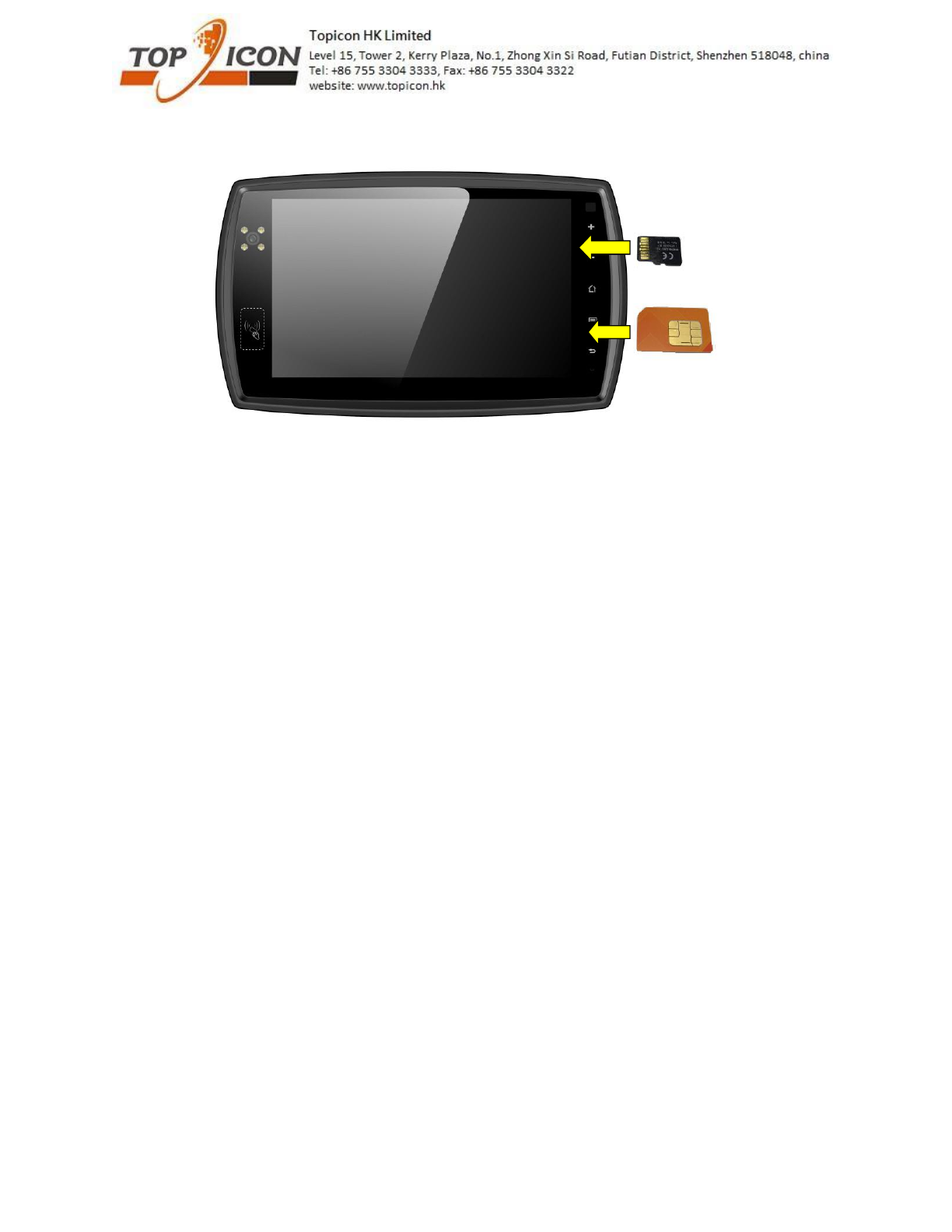
3G – pls insert the SIM card when the device if complete off
front camera – there are 6 IR LED around the camera. if you enable the flash function in front camera,
then you will see the IR LED is on. In this case, the picture will be in black and white
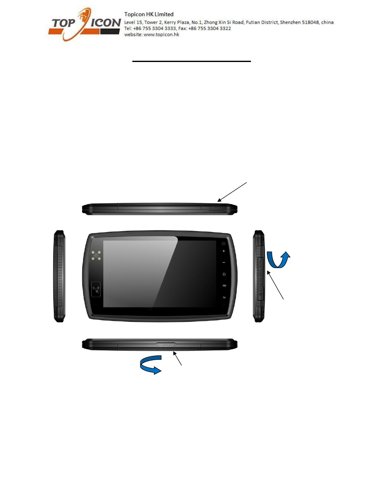
On/off button
SD card slot, SIM card slot and
reset button
Screw hole is available if you
want to lock the cover
Pls cover it well in order to
ensure the waterproof
performance
Micro usb for connecting to PC or charging
Pls cover it well in order to ensure the waterproof
performance
Pls move upward to open the
cover, you will hear “click”
sound, it is normal
Pls move right to open the
cover, you will hear “click”
sound, it is normal
All rights reserved. No part of this work may be reproduced or copied in any form or by any means (graphic, electronic, or mechanical, including photocopying,
recording, recording taping, or information and retrieval systems) without the written permission of the copyright owner
2
Direction of SIM card and SD card
All rights reserved. No part of this work may be reproduced or copied in any form or by any means (graphic, electronic, or mechanical, including photocopying,
recording, recording taping, or information and retrieval systems) without the written permission of the copyright owner
3
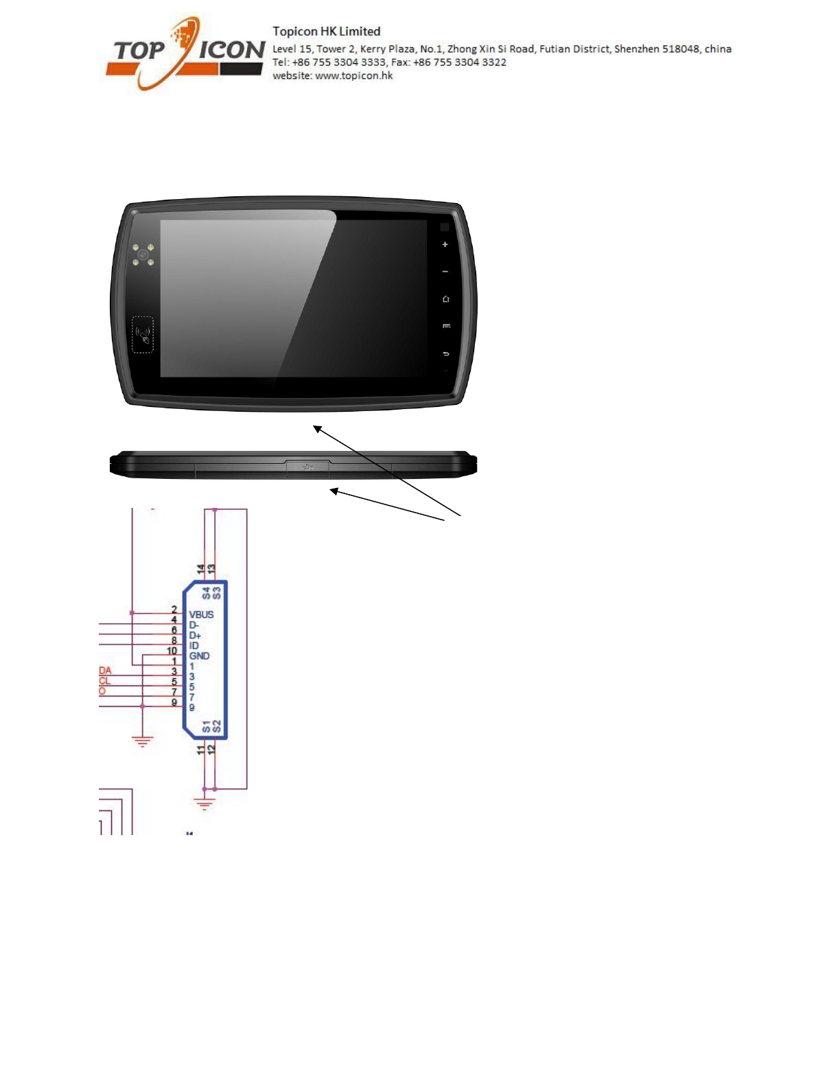
Interface
1. There is TTL serial port (Tx/RX) or OTG from 10 pin usb connector
pls see the above schematics of our USB connector in our PND, it is 10 pin connector.
Pin 4 and 6 can be used for USB or TTL serial interface (Rx/Tx) and Pin 8 is ID pin which is used to
distinguish for USB or serial interface.
if it is connected to GND, then the pin 4 and 6 will be Rx/Tx interface.
if it is connected to Vcc, then the pin 4 and 6 will be D- and D+.
10pin usb connector
All rights reserved. No part of this work may be reproduced or copied in any form or by any means (graphic, electronic, or mechanical, including photocopying,
recording, recording taping, or information and retrieval systems) without the written permission of the copyright owner
4
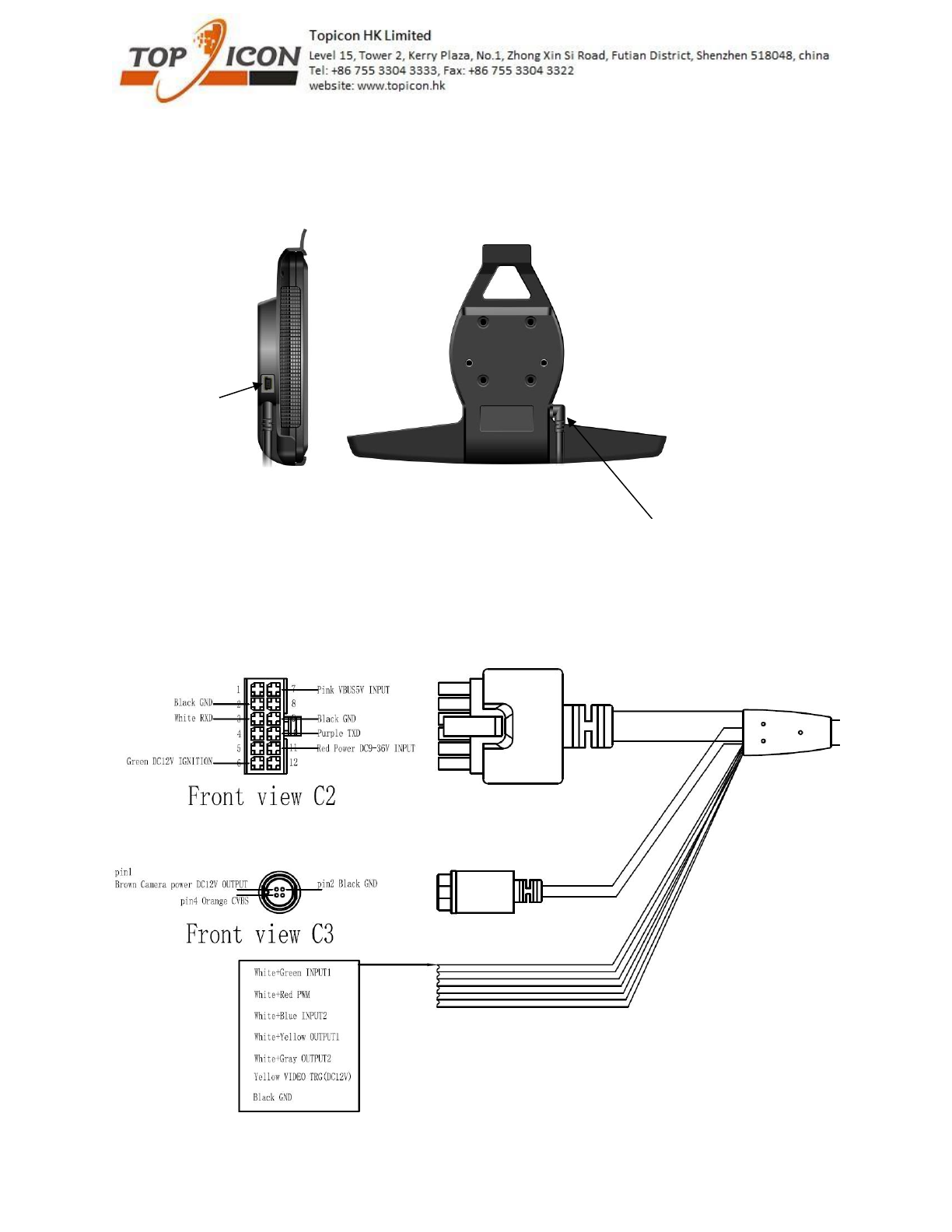
2. There are Rs232 interface and OTG from cradle.
Highlights: OTG port from device (10pin usb connector) and cradle are sharing same pins. Only 1 OTG
interface can be used.
This cable can be customized when you placed
order
For sample, it will be 12 pins connector, pls see
below or pins assignment
Usb connector for
OTG or charging
All rights reserved. No part of this work may be reproduced or copied in any form or by any means (graphic, electronic, or mechanical, including photocopying,
recording, recording taping, or information and retrieval systems) without the written permission of the copyright owner
5
Pin 1 – NOT connected
Pin 2 – GND (black)
Pin 3 – RXD (White)
Pin 4 – NOT connected
Pin 5 – NOT connected
Pin 6 – Ignition (Green), it can be wake up the device. see the software section for more details.
Pin 7 – 5V input (Pink)
Pin 8 – NOT connected
Pin 9 – GND (black)
Pin 10 – TXD (purple)
Pin 11 – car battery input (9-36V) (Red)
Pin 12 – NOT connected
Highlights: for RS232, it is master mode definition.
if you are using OTG with external device, you can only charge the device by 12V input.
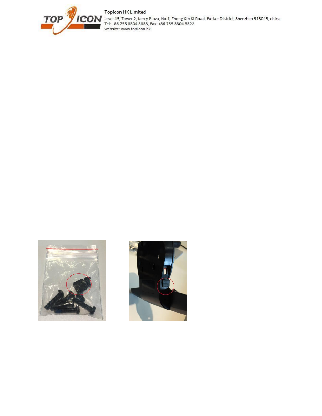
Removing the cradle cable (12pin molex connector) if you don’t want to use it.
1. you can find the rubber plug in our blackbox (see below picture).
2. open the cradle casing by screw driver
3. remove the 12pin molex cable from connector
4. put the rubber plug in the hole and close the cradle casing
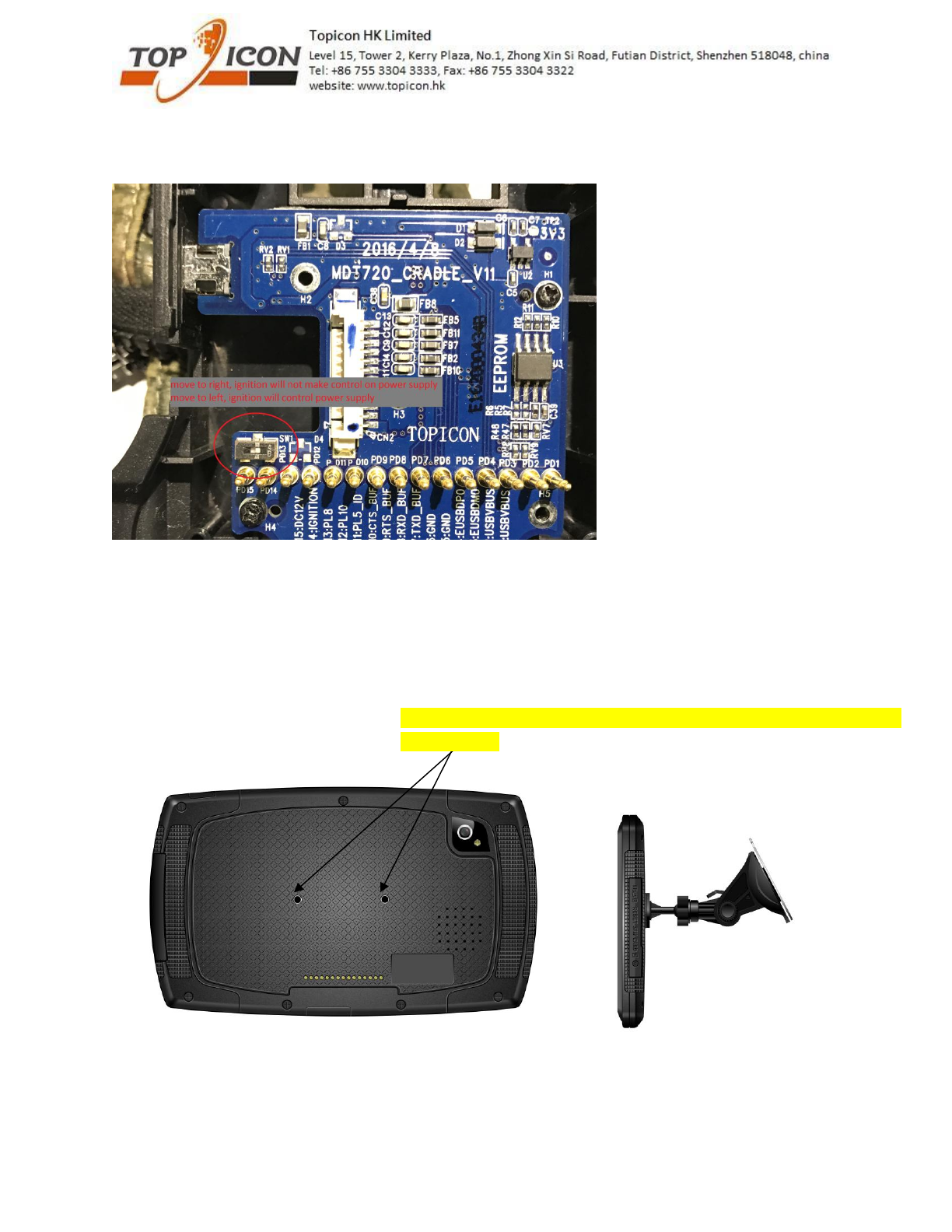
Option for ignition control the power supply
If ignition is OFF, the power supply will cut. Customer uses their application to control the device to
power off or sleep mode.
If ignition is ON, there is power supply and able to charge the device. so, when the engine is ON, the
device will power on automatically.
All rights reserved. No part of this work may be reproduced or copied in any form or by any means (graphic, electronic, or mechanical, including photocopying,
recording, recording taping, or information and retrieval systems) without the written permission of the copyright owner
6
If you want to try this feature, pls open the cradle. There are switch inside the cradle PCB. (only
production batch >1642)
Device installation
There are few options
1. Directly attach mount to device (no cradle in this case)
2 screw hole at the back
Pls use M4 15mm screw if the mount thickness is 9mm.
Pls note that the screw hole depth is only 6mm. Long screw may damge
the PCB inside
All rights reserved. No part of this work may be reproduced or copied in any form or by any means (graphic, electronic, or mechanical, including photocopying,
recording, recording taping, or information and retrieval systems) without the written permission of the copyright owner
7
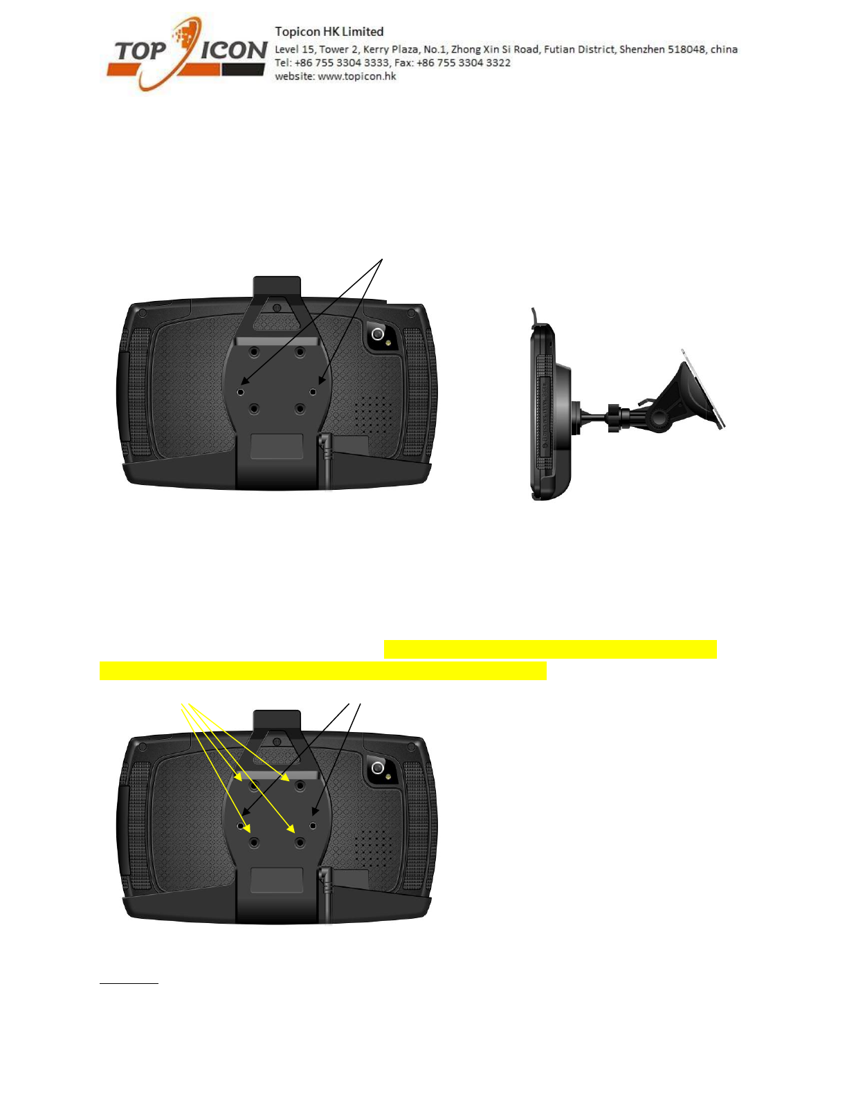
2. Cradle attached to car mount with different screw length
Mount options:
There are many car mount options. You can use the 2 screw hole (black colour) or 4 screw hole (yellow
colour) to attach the different mount system. The 4 screw hole depth is 5mm long only, pls prepare
correct screw. Pls note that wrong screw length may damage the cradle.
Option 1:
2 screw hole at the back
Case 1 – if M4 18mm screw is used, the device will be removable
from cradle
Case 2 – if M4 23mm screw is used, the device will be not
removable from cradle
All rights reserved. No part of this work may be reproduced or copied in any form or by any means (graphic, electronic, or mechanical, including photocopying,
recording, recording taping, or information and retrieval systems) without the written permission of the copyright owner
8
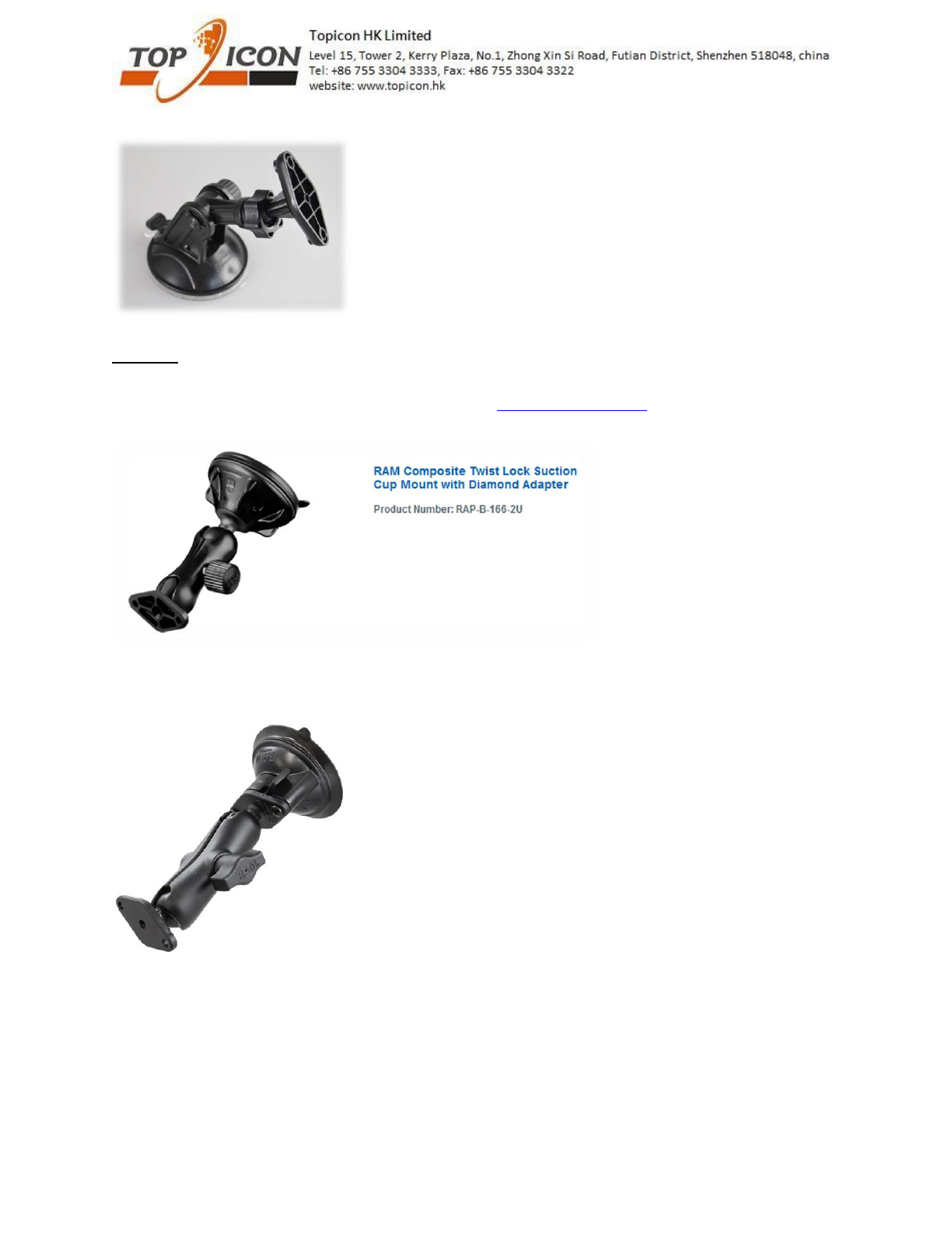
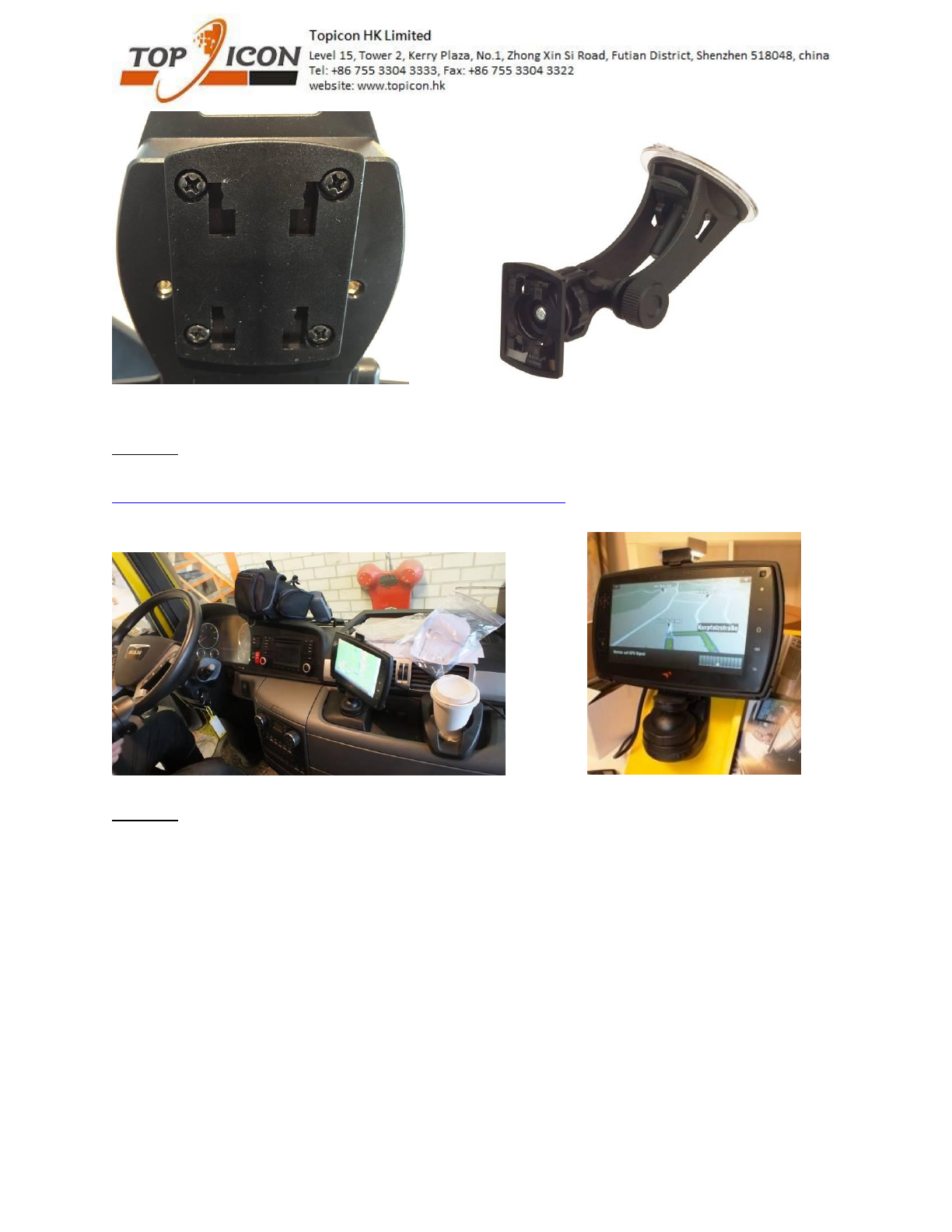
Low cost wind shield car mount
Option 2:
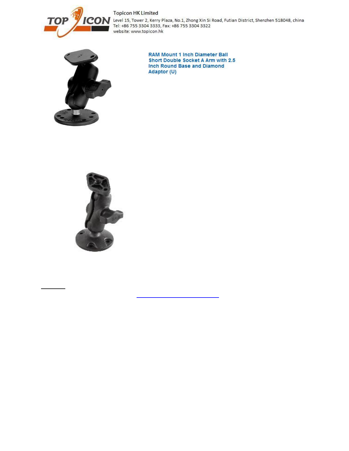
Many mount option from RAM MOUNT
You can choose the mount you like from their website (www.rammount.com)
Example 1 (RAP-B-166-2U)
Example 2 (RAM-B-138-224-1U)
Example 3 (RAM-B-138U-A)
All rights reserved. No part of this work may be reproduced or copied in any form or by any means (graphic, electronic, or mechanical, including photocopying,
recording, recording taping, or information and retrieval systems) without the written permission of the copyright owner
9
Example 4 (RAP-B-138-AU)
Option 3:
You can also choose mount from HR (http://www.hr-autocomfort.de/)
There are 4 hole plate which you can lock in the cradle with 4 screw hole. then, you can choose the
mount from HR.
Example 1 (1719/0)
All rights reserved. No part of this work may be reproduced or copied in any form or by any means (graphic, electronic, or mechanical, including photocopying,
recording, recording taping, or information and retrieval systems) without the written permission of the copyright owner
10
Option 4:
Mounting solution from truck expert (ARAT)
http://www.arat-de.eu/index.php?ber_id=10&dia_id=1&lang=en
Option 5:
There are other mount which can support this 2 screw hole and 4 screw hole at the back can be used.
For my understanding, there are other mount company also use this 2 or 4 screw hole as standard.
Pls let know if you need other mounting system or solution.
All rights reserved. No part of this work may be reproduced or copied in any form or by any means (graphic, electronic, or mechanical, including photocopying,
recording, recording taping, or information and retrieval systems) without the written permission of the copyright owner
11
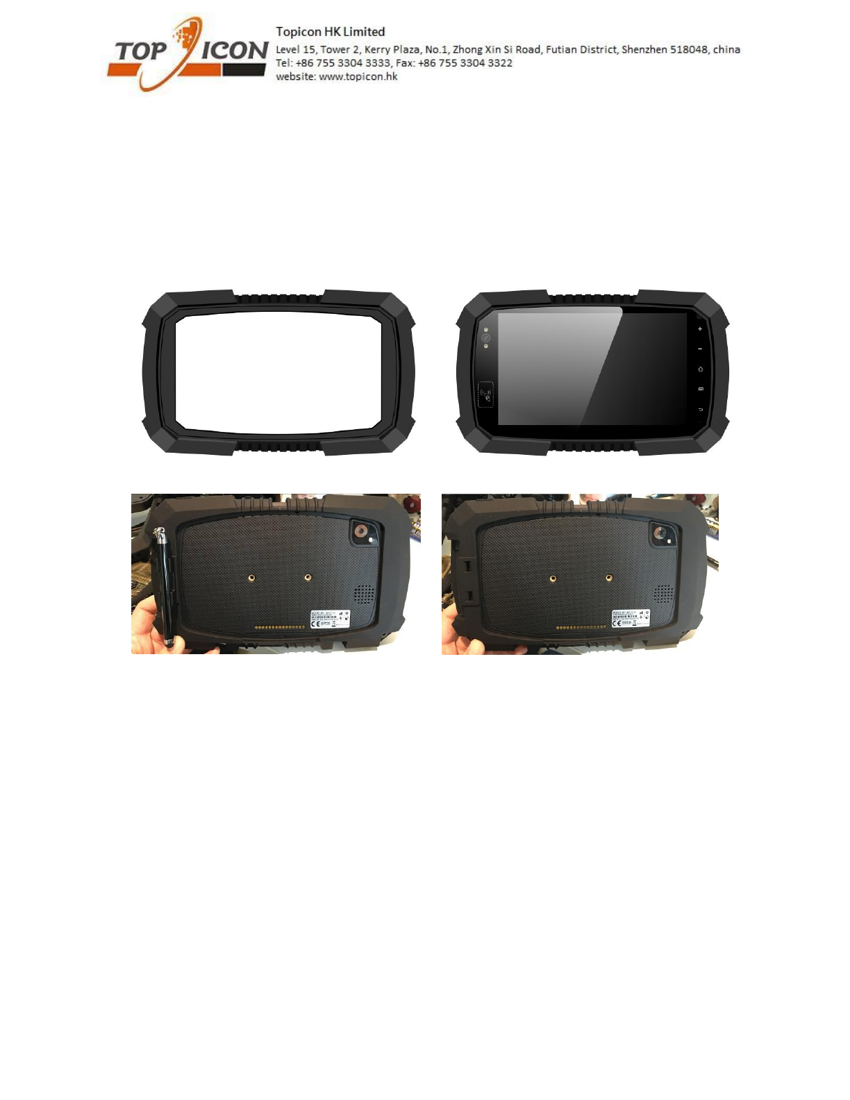
New silicon sleeve
It can have more protection for the device.
1. It also support stylus. There are optional clip which you can install at the back of the sleeve.
2. There is new cradle (dock) to match the device with sleeve. This cradle can be used for the device
with or without the sleeve.

All rights reserved. No part of this work may be reproduced or copied in any form or by any means (graphic, electronic, or mechanical, including photocopying,
recording, recording taping, or information and retrieval systems) without the written permission of the copyright owner
12
Software support
We can provide serial port apk and NFC demo. Pls contact our Sales for details.
1. Pls also see the software setting for serial port
two serial ports are available on the device :
one shares the the USB data pins of the mini A/B USB connector. Only TX and RX pins are
available, voltage is TTL 3.3V.
one is on the Pogopin interface (pins 3, 5, 6 and 7). TX, RX CTS and RTS are available, voltage is
RS232.
On the software side, the tty devices corresponding to these ports are :
for the RS232 port, /dev/user_external_tty
for the TTL port, /dev/user_tty
In addition, one I2C port is available both on the USB and Procopin connectors.
The I2C interface is accessible through /dev/user_i2c
2. if your application want to read the ignition state, pls use below API.
the 12V input is reported to the application as a key press (high level pressed, low level depressed)
in the java Android API, this key is KeyEvent.KEYCODE_TV_INPUT
A second way to access the ignition state is to register a broadcast receiver for the action
"hk.topicon.intent.action.IGNITION"
The current ignition status is given by the extra boolean "state".
This intent is sticky, ie the application will be immediately notified of the current status at registration,
even if no transition occurred.
Here is a code sniplet :
private static final String ACTION_IGNITION = "hk.topicon.intent.action.IGNITION";
private BroadcastReceiver mIgnitionReceiver = new BroadcastReceiver() {
public void onReceive(Context context, Intent intent) {
String action = intent.getAction();
if(!action.equals(ACTION_IGNITION))
return;
boolean state = intent.getBooleanExtra("state", false);
if(state)
Log.d(TAG, "ignition event is on");
else
Log.d(TAG, "ignition event is off");
}
};
FCC RF Exposure Information and Statement
This device meets the government's requirements for exposure to radio waves. The guidelines are based
on standards that were developed by independent scientific organizations through periodic and thorough
evaluation of scientific studies. The standards include a substantial safety margin designed to assure the safety of
all persons regardless of age or health. The SAR limit of USA (FCC) is 1.6 W/kg averaged. Device types: GPS
(FCC ID: 2AHAF-MDT) has also been tested against this SAR limit. SAR information on this and other pad can
be viewed on‐line at http://www.fcc.gov/oet/ea/fccid/. Please use the device FCC ID number for search. This
device was tested simulation typical 0mm to body. To maintain compliance with FCC RF exposure requirements,
the use of belt clips, holsters and similar accessories should not contain metallic components in its assembly, the
use of accessories that do not satisfy these requirements may not comply with FCC RF exposure requirements,
and should be avoided.
FCC Warning
This device complies with Part 15 of the FCC Rules. Operation is subject to the following two conditions:
(1) This device may not cause harmful interference, and (2) this device must accept any interference received,
including interference that may cause undesired operation.
NOTE 1: This equipment has been tested and found to comply with the limits for a Class B digital device,
pursuant to part 15 of the FCC Rules. These limits are designed to provide reasonable protection against harmful
interference in a residential installation. This equipment generates, uses and can radiate radio frequency energy
and, if not installed and used in accordance with the instructions, may cause harmful interference to radio
communications. However, there is no guarantee that interference will not occur in a particular installation. If this
equipment does cause harmful interference to radio or television reception, which can be determined by turning
the equipment off and on, the user is encouraged to try to correct the interference by one or more of the following
measures:
- Reorient or relocate the receiving antenna.
- Increase the separation between the equipment and receiver.
-Connect the equipment into an outlet on a circuit different from that to which the receiver is connected.
-Consult the dealer or an experienced radio/TV technician for help.
NOTE 2: Any changes or modifications to this unit not expressly approved by the party responsible for
compliance could void the user's authority to operate the equipment.