TOPICON MDT7P GPS product User Manual Business Proposal
TOPICON HK LIMITED GPS product Business Proposal
TOPICON >
User Manual
All rights reserved. No part of this work may be reproduced or copied in any form or by any means (graphic, electronic, or mechanical, including photocopying,
recording, recording taping, or information and retrieval systems) without the written permission of the copyright owner
1
Quick Start Guide
Product introduction
MDT720 has optional features (wifi, BT, GPS, 3G, back camera, front camera, RFID, lightsensor,
gyroscope, accelerometer)
Highlights:
3G – pls insert the SIM card when the device if complete off
front camera – there are 6 IR LED around the camera. if you enable the flash function in front camera,
then you will see the IR LED is on. In this case, the picture will be in black and white
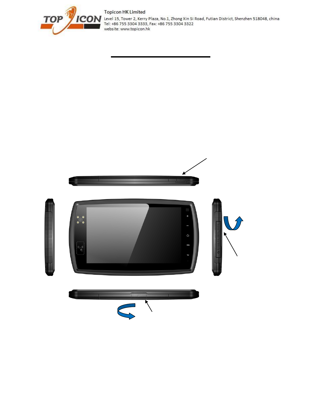
On/off button
SD card slot, SIM card slot and
reset button
Screw hole is available if you
want to lock the cover
Pls cover it well in order to
ensure the waterproof
performance
Micro usb for connecting to PC or charging
Pls cover it well in order to ensure the waterproof
performance
Pls move upward to open the
cover, you will hear “click”
sound, it is normal
Pls move right to open the
cover, you will hear “click”
sound, it is normal
All rights reserved. No part of this work may be reproduced or copied in any form or by any means (graphic, electronic, or mechanical, including photocopying,
recording, recording taping, or information and retrieval systems) without the written permission of the copyright owner
2
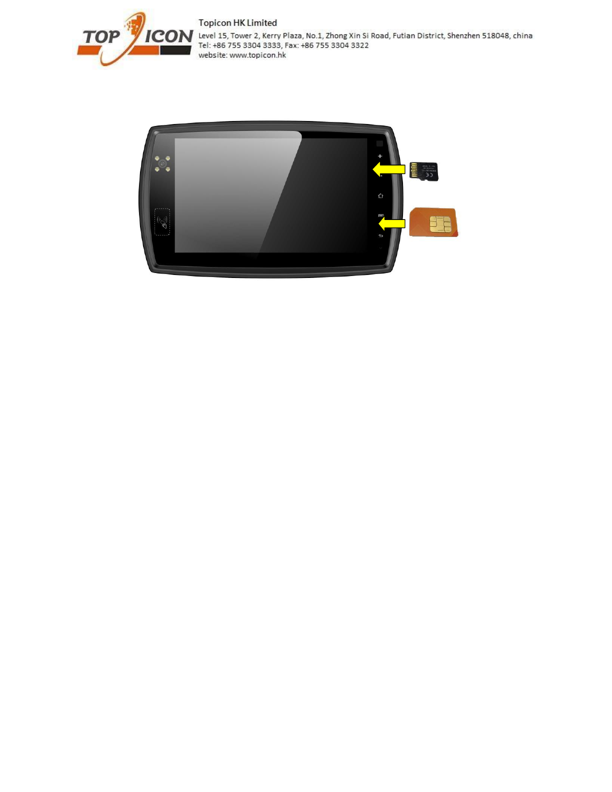
Direction of SIM card and SD card
All rights reserved. No part of this work may be reproduced or copied in any form or by any means (graphic, electronic, or mechanical, including photocopying,
recording, recording taping, or information and retrieval systems) without the written permission of the copyright owner
3
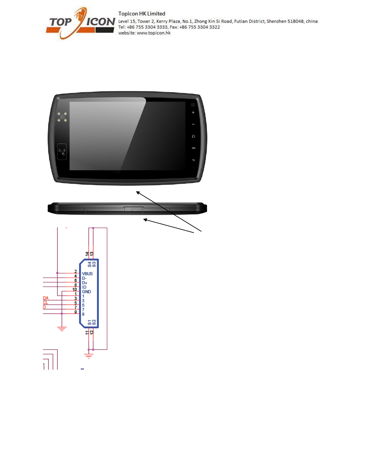
Interface
1. There is TTL serial port (Tx/RX) or OTG from 10 pin usb connector
pls see the above schematics of our USB connector in our PND, it is 10 pin connector.
Pin 4 and 6 can be used for USB or TTL serial interface (Rx/Tx) and Pin 8 is ID pin which is used to
distinguish for USB or serial interface.
if it is connected to GND, then the pin 4 and 6 will be Rx/Tx interface.
if it is connected to Vcc, then the pin 4 and 6 will be D- and D+.
10pin usb connector
All rights reserved. No part of this work may be reproduced or copied in any form or by any means (graphic, electronic, or mechanical, including photocopying,
recording, recording taping, or information and retrieval systems) without the written permission of the copyright owner
4
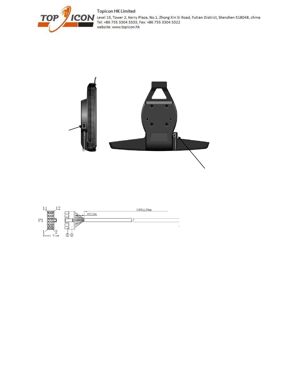
2. There are Rs232 interface and OTG from cradle.
Highlights: OTG port from device (10pin usb connector) and cradle are sharing same pins. Only 1 OTG
interface can be used.
Pin 1 – Ignition (white)
Pin 2 – GPIO (reserved) (green)
Pin 3 – CTS (red)
Pin 4 – car battery input (12-28V) (black)
Pin 5 – RTS (blue)
Pin 6 – RXD (yellow)
Pin 7 – TXD (purple)
Pin 8 – GND (grey)
Pin 9 – GND (orange)
Pin 10 – NOT connected (brown)
Pin 11 – NOT connected (pink)
Pin 12 – 5V input (white-black)
Higlights: if you are using OTG with external device, you can only charge the device by 12V input.
This cable can be customized when you placed
order
For sample, it will be 12 pins connector, pls see
below or pins assignment
Usb connector for
OTG or charging
All rights reserved. No part of this work may be reproduced or copied in any form or by any means (graphic, electronic, or mechanical, including photocopying,
recording, recording taping, or information and retrieval systems) without the written permission of the copyright owner
5
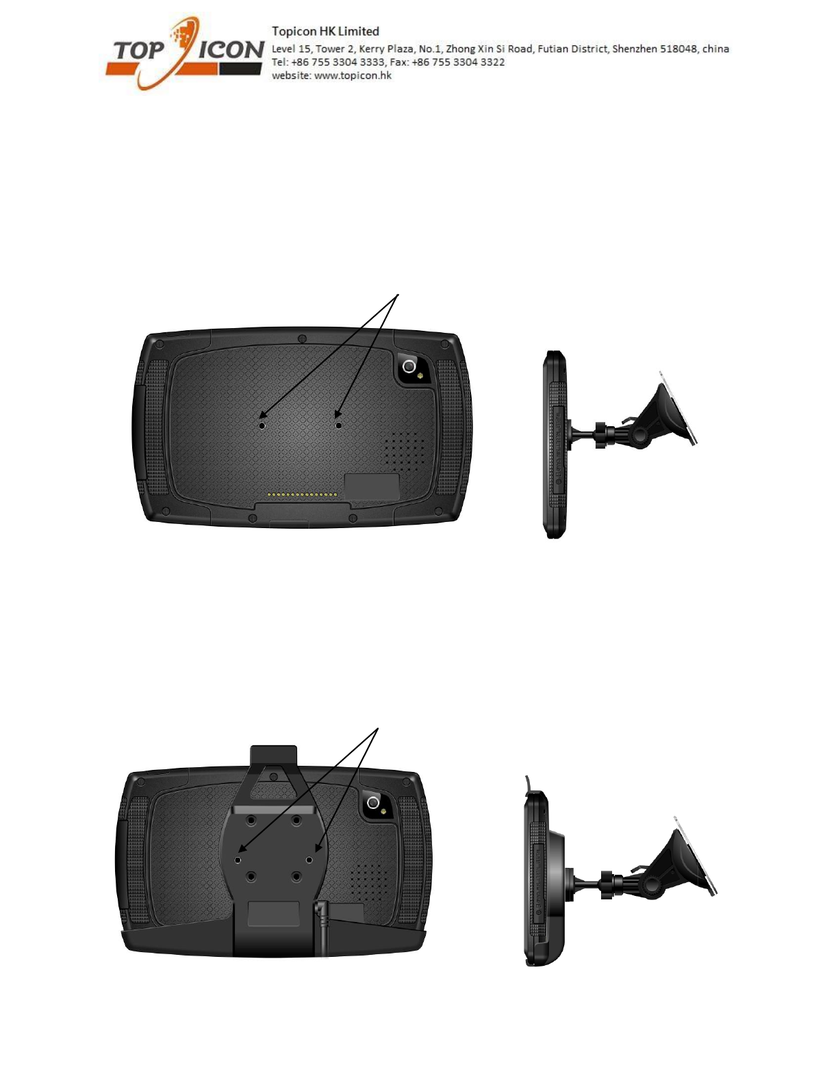
Device installation
There are few options
1. Directly attach mount to device (no cradle in this case)
2. Cradle attached to car mount with different screw length
2 screw hole at the back
Pls use M4 18mm screw
2 screw hole at the back
Pls use M4 18mm screw
2 screw hole at the back
Case 1 – if M4 18mm screw is used, the device will be removable
from cradle
Case 2 – if M4 23mm screw is used, the device will be not
removable from cradle
All rights reserved. No part of this work may be reproduced or copied in any form or by any means (graphic, electronic, or mechanical, including photocopying,
recording, recording taping, or information and retrieval systems) without the written permission of the copyright owner
6
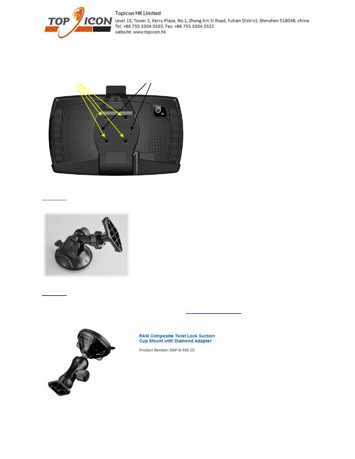
Mount options:
There are many car mount options. You can use the 2 screw hole (black colour) or 4 screw hole (yellow
colour) to attach the different mount system.
Option 1:
Low cost wind shield car mount
Option 2:
Many mount option from RAM MOUNT
You can choose the mount you like from their website (www.rammount.com)
Example 1 (RAP-B-166-2U)
All rights reserved. No part of this work may be reproduced or copied in any form or by any means (graphic, electronic, or mechanical, including photocopying,
recording, recording taping, or information and retrieval systems) without the written permission of the copyright owner
7
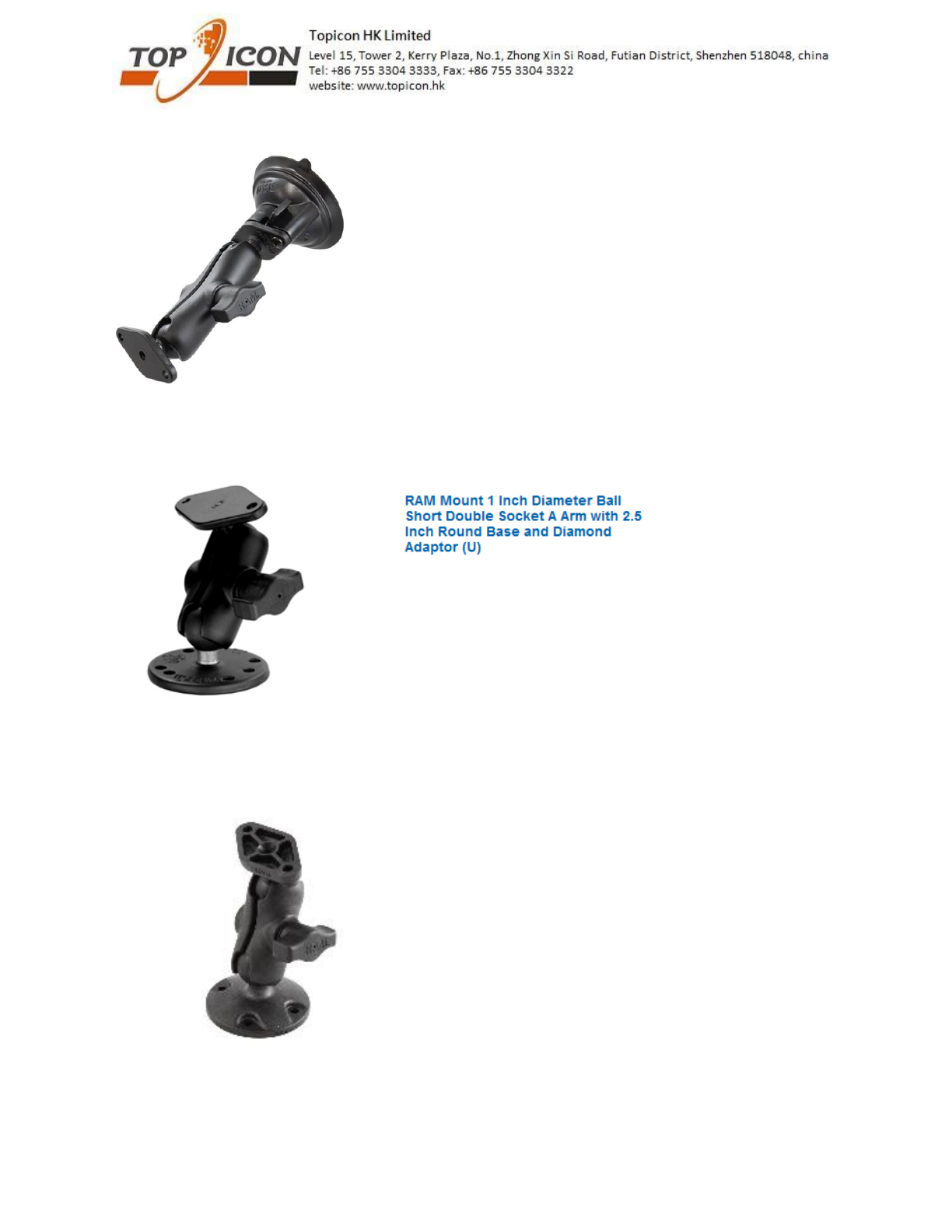
Example 2 (RAP-B-166-2U)
Example 3 (RAM-B-138U-A)
Example 4 (RAP-B-138-AU)
All rights reserved. No part of this work may be reproduced or copied in any form or by any means (graphic, electronic, or mechanical, including photocopying,
recording, recording taping, or information and retrieval systems) without the written permission of the copyright owner
8
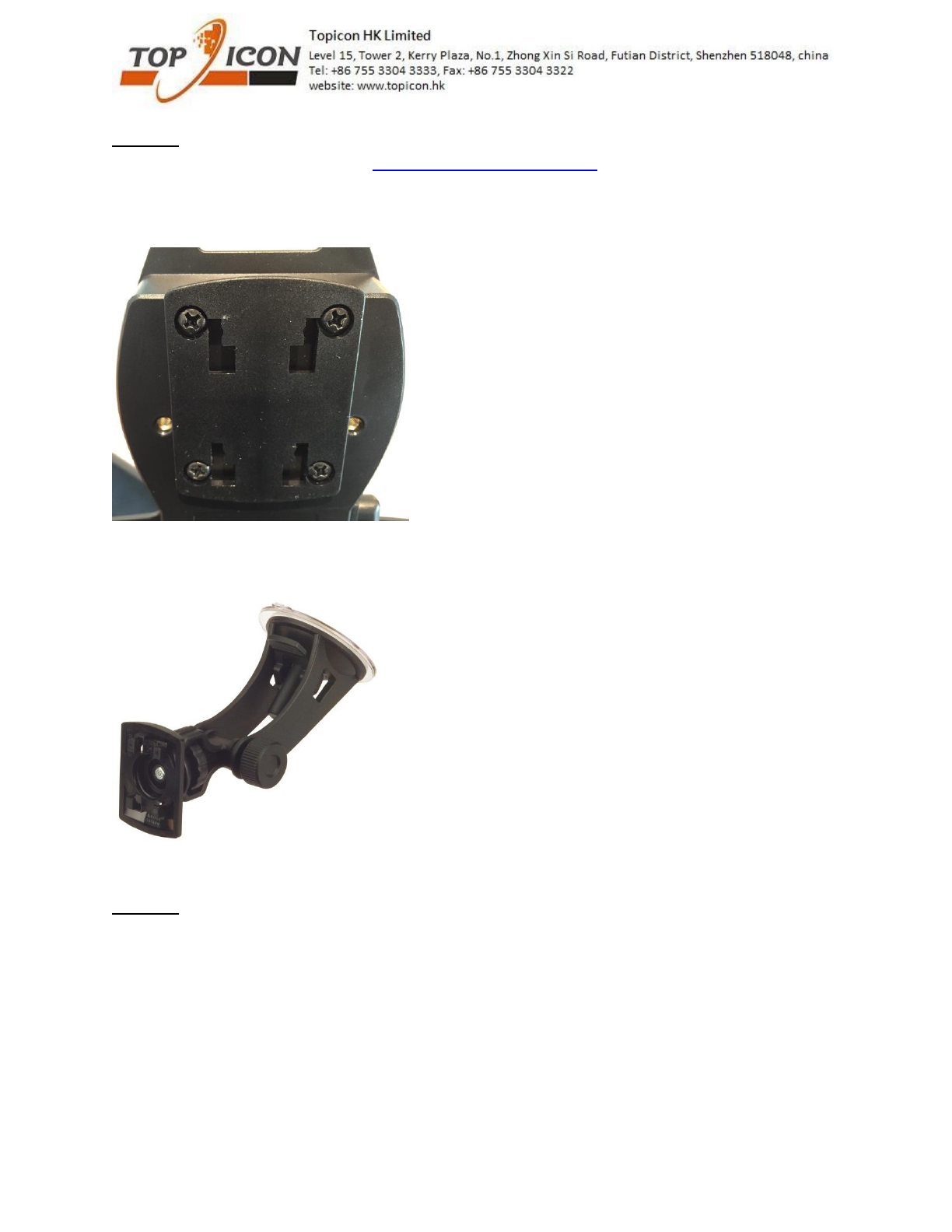
Option 3:
You can also choose mount from HR (http://www.hr-autocomfort.de/)
There are 4 hole plate which you can lock in the cradle with 4 screw hole. then, you can choose the
mount from HR.
Example 1 (1719/0)
Option 4:
There are other mount which can support this 2 screw hole and 4 screw hole at the back can be used.
For my understanding, there are other mount company also use this 2 or 4 screw hole as standard.
Pls let know if you need other mounting system or solution.

All rights reserved. No part of this work may be reproduced or copied in any form or by any means (graphic, electronic, or mechanical, including photocopying,
recording, recording taping, or information and retrieval systems) without the written permission of the copyright owner
9
Software support
We can provide serial port apk and NFC demo. Pls contact our Sales for details.
Pls also see the software setting for serial port
two serial ports are available one the device :
one shares the the USB data pins of the mini A/B USB connector. Only TX and RX pins are
available, voltage is TTL 3.3V.
one is on the Pogopin interface (pins 3, 5, 6 and 7). TX, RX CTS and RTS are available, voltage is
RS232.
On the software side, the tty devices corresponding to these ports are :
for the RS232 port, /dev/user_external_tty
RS232 interface need to be enable prior to use :
$> echo 1 > /dev/enable_external_tty
After use, it can be disabled with :
$> echo 0 > /dev/enable_external_tty
for the TTL port, /dev/user_tty
In addition, one I2C port is available both on the USB and Procopin connectors.
The I2C interface is accessible through /dev/user_i2c
accessible through /dev/user_i2c
FCC RF Exposure Information and Statement
The SAR limit of USA (FCC) is 1.6 W/kg averaged over one gram of tissue. Device types GPS
product (FCC ID: 2AHAF-MDT7P) has also been tested against this SAR limit. The highest
reported SAR values for body is 0.841W/kg. This device was tested for typical body operations
with the back of the tablet kept 0mm from the body. To maintain compliance with FCC RF
exposure requirements, use accessories that maintain a 0mm separation distance between the
user's body and the back of the tablet. The use of belt clips, holsters and similar accessories should
not contain metallic components in its assembly. The use of accessories that do not satisfy these
requirements may not comply with FCC RF exposure requirements, and should be avoided.
FCC Warning
This device complies with Part 15 of the FCC Rules. Operation is subject to the following two
conditions:
(1) This device may not cause harmful interference, and (2) this device must accept any
interference received, including interference that may cause undesired operation.
NOTE 1: This equipment has been tested and found to comply with the limits for a Class B digital
device, pursuant to part 15 of the FCC Rules. These limits are designed to provide reasonable
protection against harmful interference in a residential installation. This equipment generates, uses
and can radiate radio frequency energy and, if not installed and used in accordance with the
instructions, may cause harmful interference to radio communications. However, there is no
guarantee that interference will not occur in a particular installation. If this equipment does cause
harmful interference to radio or television reception, which can be determined by turning the
equipment off and on, the user is encouraged to try to correct the interference by one or more of
the following measures:
- Reorient or relocate the receiving antenna.
- Increase the separation between the equipment and receiver.
-Connect the equipment into an outlet on a circuit different from that to which the receiver is
connected.
-Consult the dealer or an experienced radio/TV technician for help.
NOTE 2: Any changes or modifications to this unit not expressly approved by the party
responsible for compliance could void the user's authority to operate the equipment.
Information to Users
According to the RSS-Gen section 8.4 and RSP-100 section 3.2, for this EUT, the instructions or
operation manual furnished the user shall include the following or similar statement, placed in a
prominent location in the text of the manual:
IC WARNING
This device complies with Industry Canada’s licence-exempt RSSs. Operation is subject to the
following two conditions:
(1) This device may not cause interference; and
(2) This device must accept any interference, including interference that may cause undesired
operation of the device.
Le présent appareil est conforme aux CNR d'Industrie Canada applicables aux appareils radio
exempts de licence. L'exploitation est autorisée aux deux conditions suivantes: (1) l'appareil ne
doit pas produire de brouillage, et (2) l'utilisateur de l'appareil doit accepter tout brouillage
radioélectrique subi, même si le brouillage est susceptible d'en compromettre le fonctionnement.