TP Link Technologies C1200 AC1200 Wireless Dual Band Gigabit Router User Manual
TP-Link Technologies Co., Ltd. AC1200 Wireless Dual Band Gigabit Router
Contents
- 1. Archer C1200_User Manual-2016-08-08
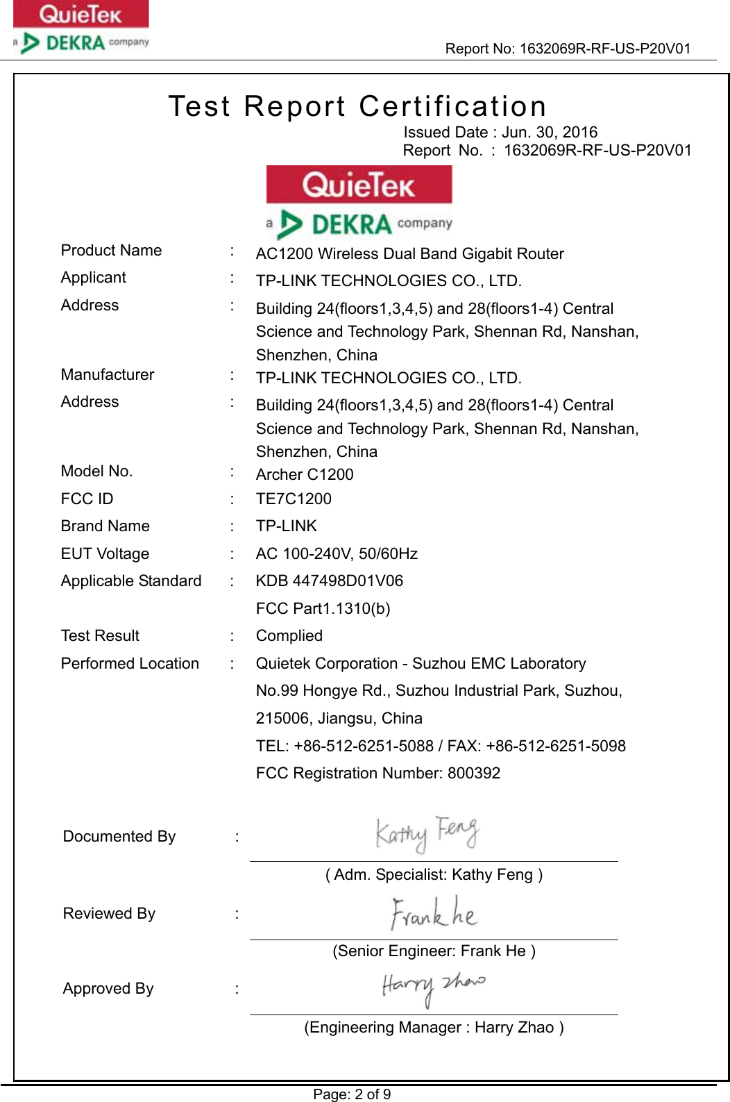
- 2. 1632069R-FCC-RF Exposure-Archer C1200-V1.1-2016-07-05
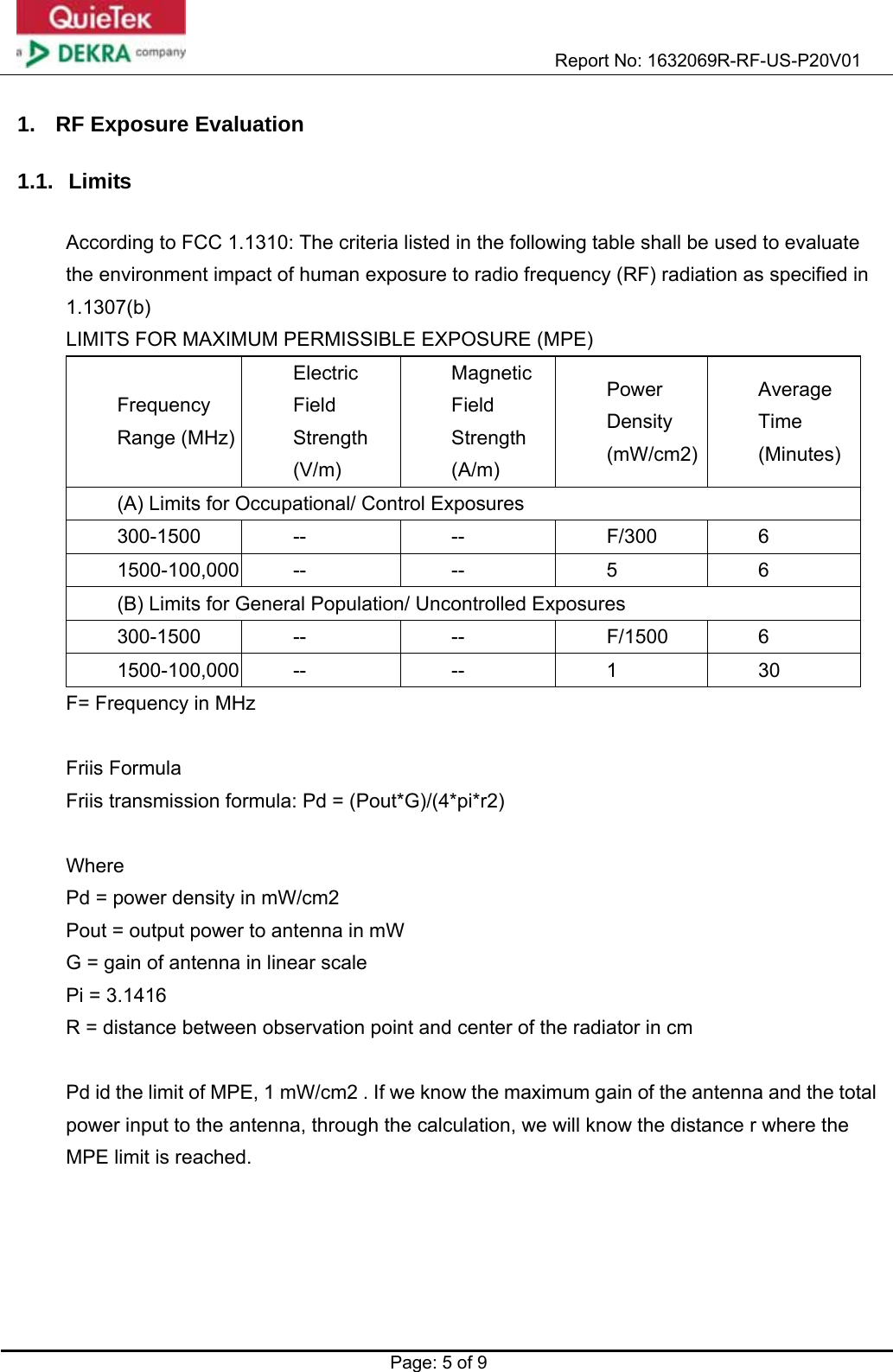
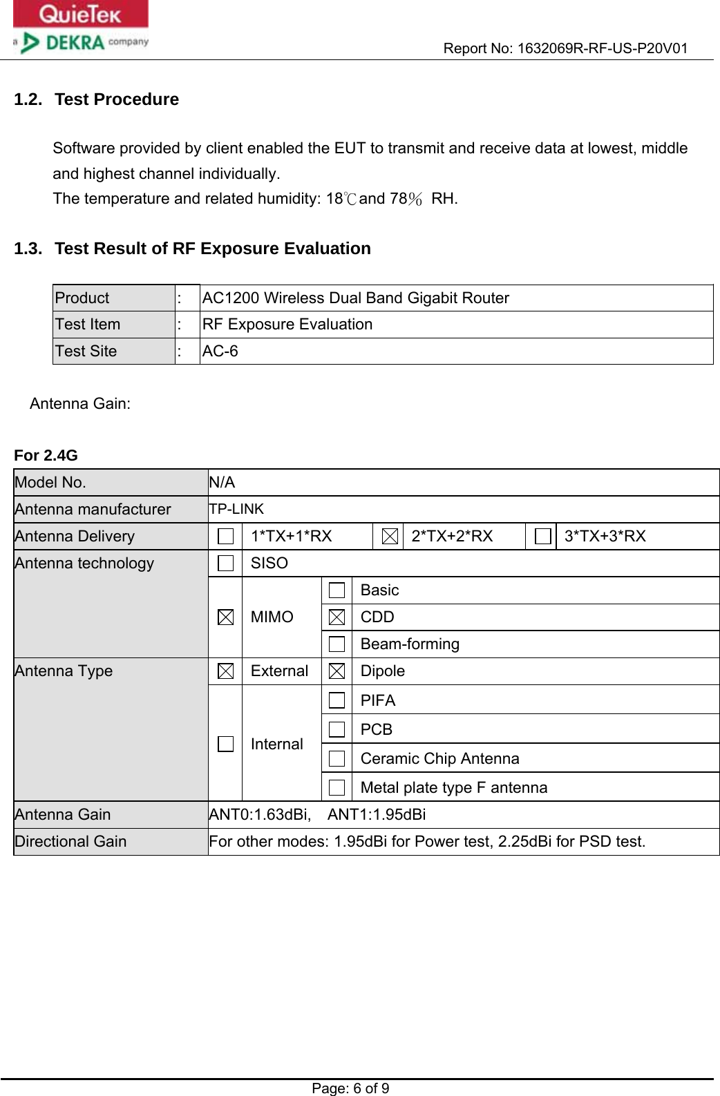
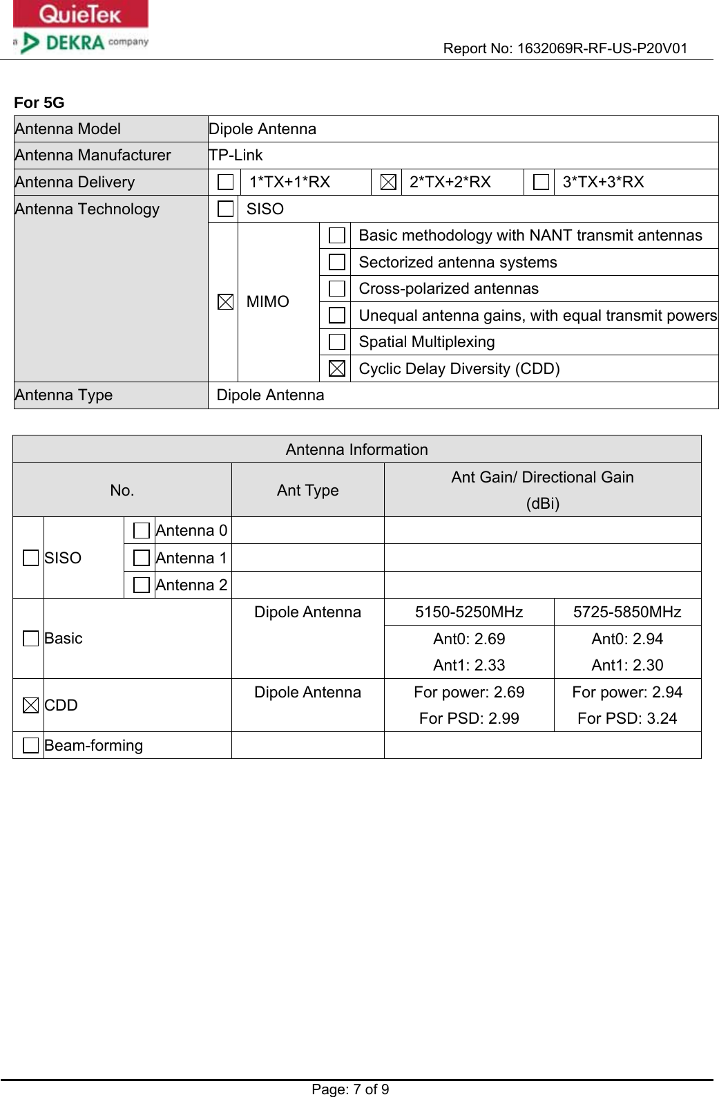
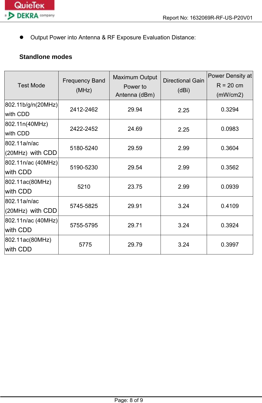
1632069R-FCC-RF Exposure-Archer C1200-V1.1-2016-07-05