TP Link Technologies C1200 AC1200 Wireless Dual Band Gigabit Router User Manual
TP-Link Technologies Co., Ltd. AC1200 Wireless Dual Band Gigabit Router
Contents
- 1. Archer C1200_User Manual-2016-08-08
- 2. 1632069R-FCC-RF Exposure-Archer C1200-V1.1-2016-07-05
1632069R-FCC-RF Exposure-Archer C1200-V1.1-2016-07-05

RF Exposure Evaluation Declaration
Product Name : AC1200 Wireless Dual Band Gigabit Router
Model No. : Archer C1200
FCC ID : TE7C1200
Applicant : TP-LINK TECHNOLOGIES CO., LTD.
Address : Building 24(floors1,3,4,5) and 28(floors1-4) Central
Science and Technology Park, Shennan Rd,
Nanshan, Shenzhen, China
Date of Receipt : Mar. 16, 2016
Issued Date : Jun. 30, 2016
Report No. : 1632069R-RF-US-P20V01
Report Version : V1.1
The test results relate only to the samples tested.
The test results shown in the test report are traceable to the national/international standard through the
calibration of the equipment and evaluated measurement uncertainty herein.
This report must not be used to claim product endorsement by TAF,CNAS or any agency of the government.
The test report shall not be reproduced without the written approval of QuieTek Corporation.
Report No: 1632069R-RF-US-P20V01
Page: 2 of 9
Test Report Certification
Issued Date : Jun. 30, 2016
Report No. : 1632069R-RF-US-P20V01
Product Name : AC1200 Wireless Dual Band Gigabit Router
Applicant :
TP-LINK TECHNOLOGIES CO., LTD.
Address :
Building 24(floors1,3,4,5) and 28(floors1-4) Central
Science and Technology Park, Shennan Rd, Nanshan,
Shenzhen, China
Manufacturer :
TP-LINK TECHNOLOGIES CO., LTD.
Address :
Building 24(floors1,3,4,5) and 28(floors1-4) Central
Science and Technology Park, Shennan Rd, Nanshan,
Shenzhen, China
Model No. : Archer C1200
FCC ID : TE7C1200
Brand Name : TP-LINK
EUT Voltage : AC 100-240V, 50/60Hz
Applicable Standard : KDB 447498D01V06
FCC Part1.1310(b)
Test Result : Complied
Performed Location : Quietek Corporation - Suzhou EMC Laboratory
No.99 Hongye Rd., Suzhou Industrial Park, Suzhou,
215006, Jiangsu, China
TEL: +86-512-6251-5088 / FAX: +86-512-6251-5098
FCC Registration Number: 800392
Documented By :
( Adm. Specialist: Kathy Feng )
Reviewed By :
(Senior Engineer: Frank He )
Approved By :
(Engineering Manager : Harry Zhao )

Report No: 1632069R-RF-US-P20V01
Page: 3 of 9
Laboratory Information
We, QuieTek Corporation, are an independent EMC and safety consultancy that was
established the whole facility in our laboratories. The test facility has been
accredited/accepted(audited or listed) by the following related bodies in compliance with ISO
17025, EN 45001 and specified testing scope:
The related certificate for our laboratories about the test site and management system can be downloaded
from QuieTek Corporation’s Web Site : http://www.quietek.com/english/about/certificates.aspx?bval=5
The address and introduction of QuieTek Corporation’s laboratories can be founded in our Web site :
http://www.quietek.com/index_en.aspx
If you have any comments, Please don’t hesitate to contact us. Our contact information is as below:
HsinChu Testing Laboratory :
No.75-2, 3rd Lin, Wangye Keng, Yonghxing Tsuen, Qionglin Shiang, Hsinchu County 307, Taiwan, R.O.C.
TEL:+886-3-592-8858 / FAX:+886-3-592-8859 E-Mail : service@quietek.com
LinKou Testing Laboratory :
No.5-22, Ruishukeng, Linkou Dist., New Taipei City 24451, Taiwan, R.O.C.
TEL : 886-2-8601-3788 / FAX : 886-2-8601-3789 E-Mail : service@quietek.com
Suzhou Testing Laboratory :
No.99 Hongye Rd., Suzhou Industrial Park, Suzhou, 215006, Jiangsu, China
TEL : +86-512-6251-5088 / FAX : 86-512-6251-5098 E-Mail : service@quietek.com
Taiwan R.O.C. :BSMI, NCC, TAF
USA :FCC
Japan :VCCI
China :CNAS

Report No: 1632069R-RF-US-P20V01
Page: 4 of 9
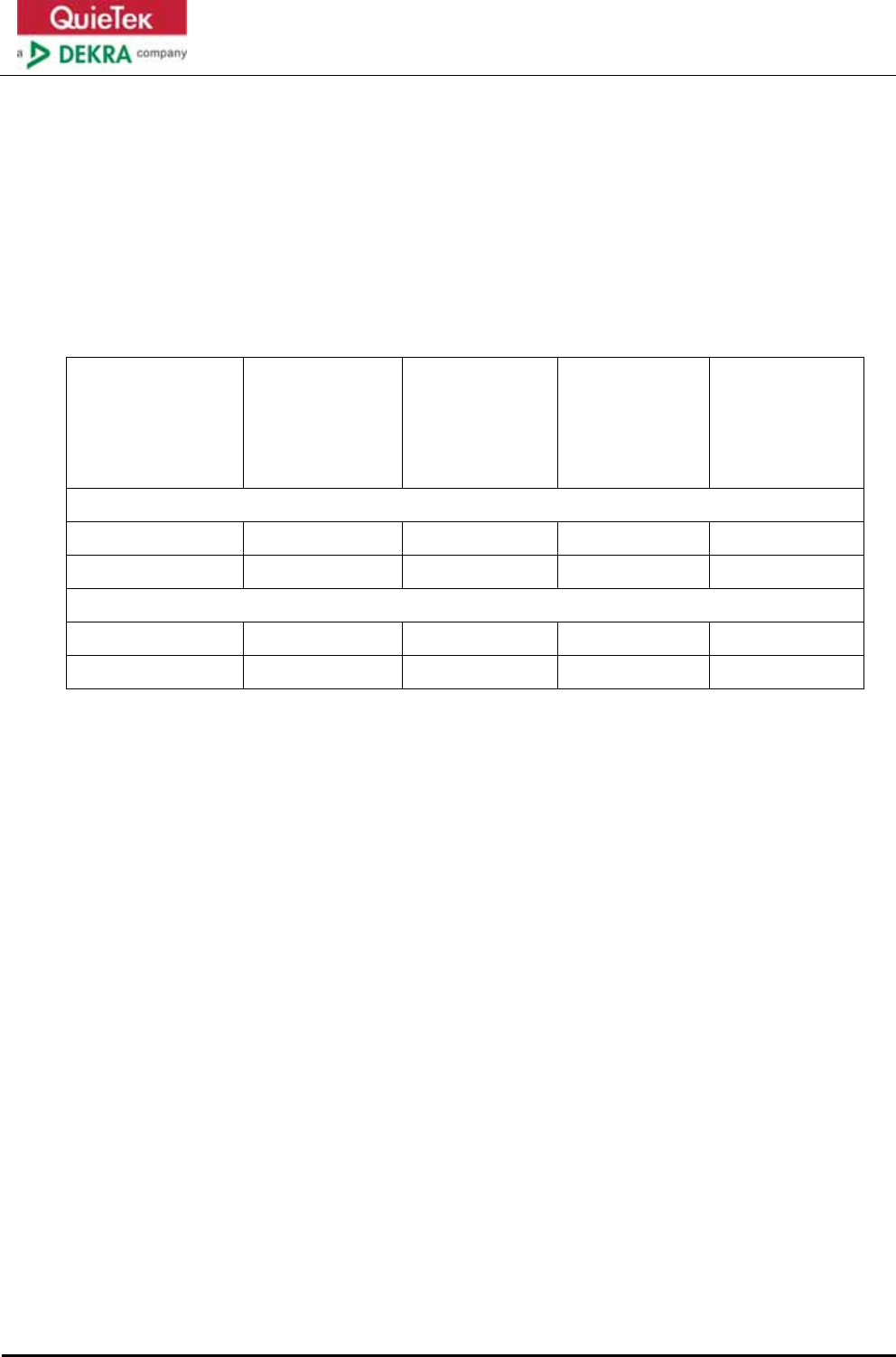
History of This Test Report
REPORT NO. VERSION DESCRIPTION ISSUED DATE
1632069R-RF-US-P20V01 V1.0 Initial Issued Report Jun. 23, 2016
1632069R-RF-US-P20V01 V1.1 Modify frequency range in 2.4G Jun. 30, 2016
Report No: 1632069R-RF-US-P20V01
Page: 5 of 9
1. RF Exposure Evaluation
1.1. Limits
According to FCC 1.1310: The criteria listed in the following table shall be used to evaluate
the environment impact of human exposure to radio frequency (RF) radiation as specified in
1.1307(b)
LIMITS FOR MAXIMUM PERMISSIBLE EXPOSURE (MPE)
Frequency
Range (MHz)
Electric
Field
Strength
(V/m)
Magnetic
Field
Strength
(A/m)
Power
Density
(mW/cm2)
Average
Time
(Minutes)
(A) Limits for Occupational/ Control Exposures
300-1500 -- -- F/300 6
1500-100,000 -- -- 5 6
(B) Limits for General Population/ Uncontrolled Exposures
300-1500 -- -- F/1500 6
1500-100,000 -- -- 1 30
F= Frequency in MHz
Friis Formula
Friis transmission formula: Pd = (Pout*G)/(4*pi*r2)
Where
Pd = power density in mW/cm2
Pout = output power to antenna in mW
G = gain of antenna in linear scale
Pi = 3.1416
R = distance between observation point and center of the radiator in cm
Pd id the limit of MPE, 1 mW/cm2 . If we know the maximum gain of the antenna and the total
power input to the antenna, through the calculation, we will know the distance r where the
MPE limit is reached.
Report No: 1632069R-RF-US-P20V01
Page: 6 of 9
1.2. Test Procedure
Software provided by client enabled the EUT to transmit and receive data at lowest, middle
and highest channel individually.
The temperature and related humidity: 18℃and 78% RH.
1.3. Test Result of RF Exposure Evaluation
Product : AC1200 Wireless Dual Band Gigabit Router
Test Item : RF Exposure Evaluation
Test Site : AC-6
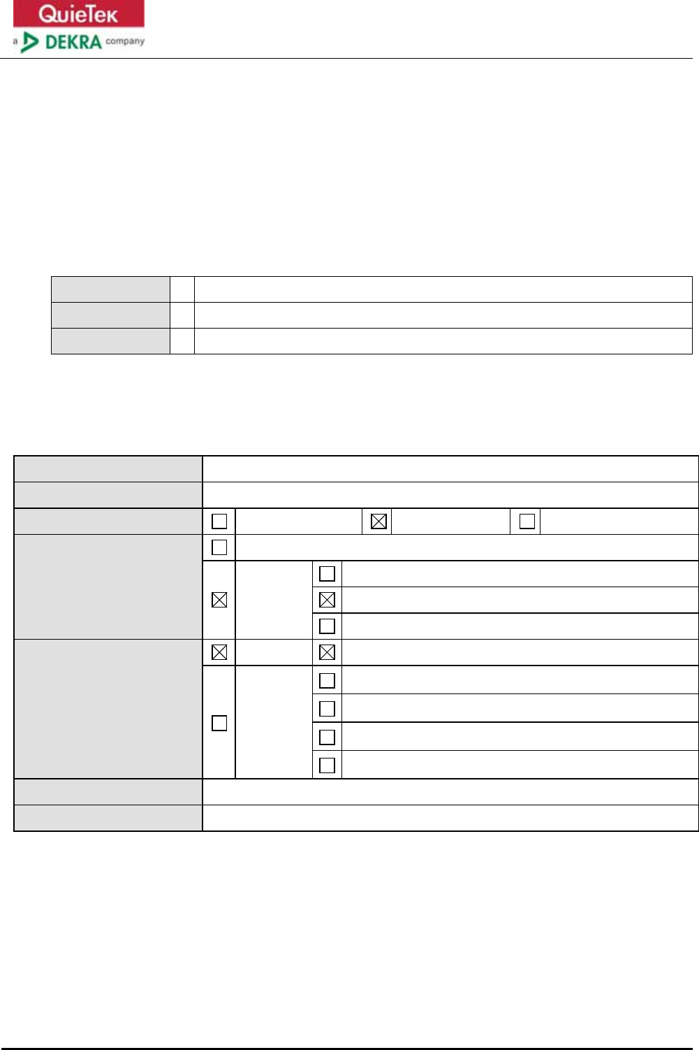
Antenna Gain:
For 2.4G
Model No. N/A
Antenna manufacturer TP-LINK
Antenna Delivery 1*TX+1*RX 2*TX+2*RX 3*TX+3*RX
Antenna technology SISO
MIMO
Basic
CDD
Beam-forming
Antenna Type External Dipole
Internal
PIFA
PCB
Ceramic Chip Antenna
Metal plate type F antenna
Antenna Gain ANT0:1.63dBi, ANT1:1.95dBi
Directional Gain For other modes: 1.95dBi for Power test, 2.25dBi for PSD test.
Report No: 1632069R-RF-US-P20V01
Page: 7 of 9
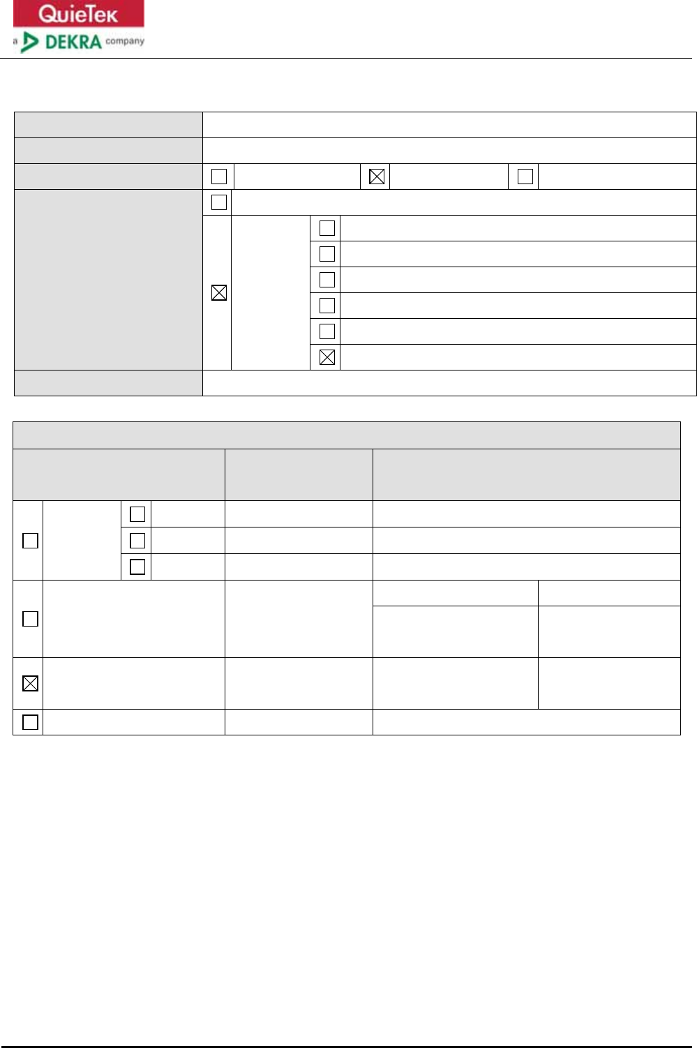
For 5G
Antenna Model Dipole Antenna
Antenna Manufacturer TP-Link
Antenna Delivery 1*TX+1*RX 2*TX+2*RX 3*TX+3*RX
Antenna Technology SISO
MIMO
Basic methodology with NANT transmit antennas
Sectorized antenna systems
Cross-polarized antennas
Unequal antenna gains, with equal transmit powers
Spatial Multiplexing
Cyclic Delay Diversity (CDD)
Antenna Type Dipole Antenna
Antenna Information
No. Ant Type Ant Gain/ Directional Gain
(dBi)
SISO
Antenna 0
Antenna 1
Antenna 2
Basic
Dipole Antenna 5150-5250MHz 5725-5850MHz
Ant0: 2.69
Ant1: 2.33
Ant0: 2.94
Ant1: 2.30
CDD Dipole Antenna For power: 2.69
For PSD: 2.99
For power: 2.94
For PSD: 3.24
Beam-forming

Report No: 1632069R-RF-US-P20V01
Page: 8 of 9
z Output Power into Antenna & RF Exposure Evaluation Distance:
Standlone modes
Test Mode Frequency Band
(MHz)
Maximum Output
Power to
Antenna (dBm)
Directional Gain
(dBi)
Power Density at
R = 20 cm
(mW/cm2)
802.11b/g/n(20MHz)
with CDD 2412-2462 29.94 2.25 0.3294
802.11n(40MHz)
with CDD 2422-2452 24.69 2.25 0.0983
802.11a/n/ac
(20MHz) with CDD 5180-5240 29.59 2.99 0.3604
802.11n/ac (40MHz)
with CDD 5190-5230 29.54 2.99 0.3562
802.11ac(80MHz)
with CDD 5210 23.75 2.99 0.0939
802.11a/n/ac
(20MHz) with CDD 5745-5825 29.91 3.24 0.4109
802.11n/ac (40MHz)
with CDD 5755-5795 29.71 3.24 0.3924
802.11ac(80MHz)
with CDD 5775 29.79 3.24 0.3997
Report No: 1632069R-RF-US-P20V01
Page: 9 of 9
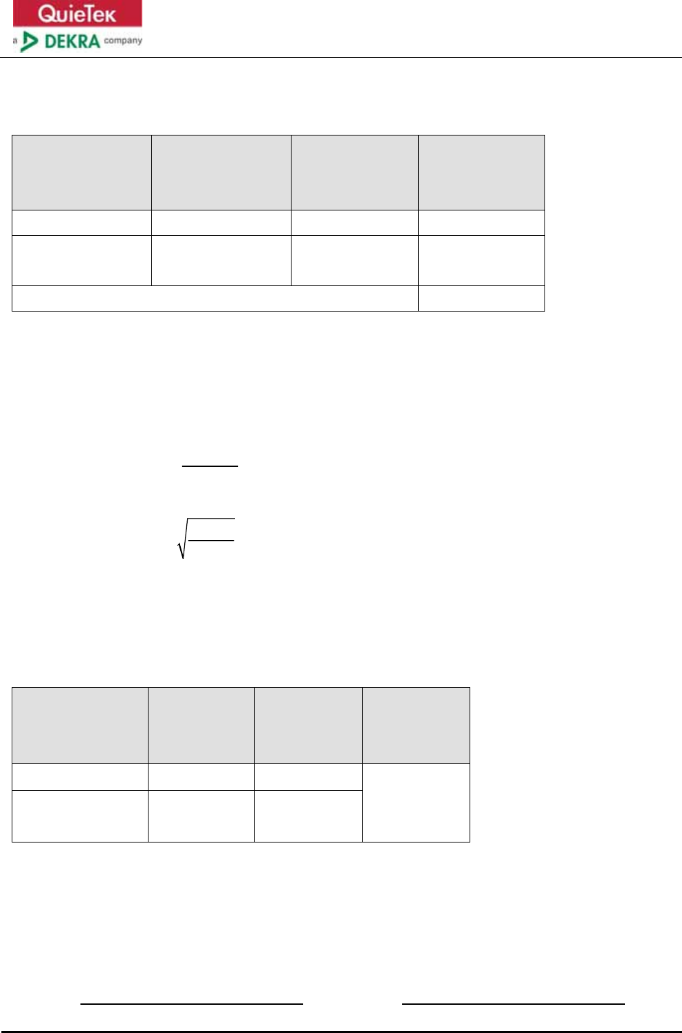
Simultaneous transmission:
Frequency Band
(MHz)
Maximum Output
Power to
Antenna (dBm)
Directional Gain
(dBi)
Power Density at
R = 20 cm
(mW/cm2)
2412-2462 29.94 2.25 0.3294
5180-5240
5745-5825 29.91 3.24
0.4109
Simultaneous transmission power density 0.7403
So according to transmission formula: Pd = (Pout*G)/(4*pi*r2) and the power density limit
according to KDB 447498D01V06 and FCC Part1.1310(b), the limit is 1mW/cm2
Safety Distance Calculation Formula:
The power flux:
S = (,)
2
P*G
4* *r
θ
φ
π
So safety distance as following:
r = *
4* *S
PG
π
P = input power of the antenna
G = antenna gain relative to an isotropic antenna
θ, Ф = elevation and azimuth angles.
r = distance from the antenna to the point of investigation
Frequency Range
(MHz)
Maximum
EIRP
(dBm)
Limit of Power
Density
S(mW/cm2)
Safety Distance
r(cm)
2412-2462 32.19 1
12.82
5180-5240
5745-5825 33.15 1
Note: The safety distance is 12.82cm for AC1200 Wireless Dual Band Gigabit Router without
any other radio equipment.
The End