TP Link Technologies CPE210 2.4 GHz 300Mpbs 9dBi Outdoor CPE User Manual CPE210 updated PART2
TP-Link Technologies Co., Ltd. 2.4 GHz 300Mpbs 9dBi Outdoor CPE CPE210 updated PART2
Contents
- 1. CPE210_User Manual_updated-PART1
- 2. CPE210_User Manual_updated-PART2
CPE210_User Manual_updated-PART2
12
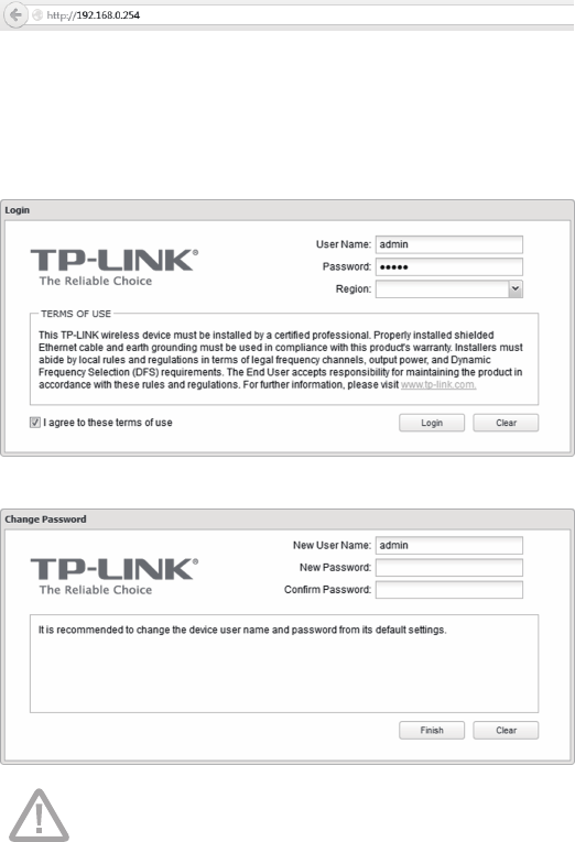
2. Open your web browser, type 'http://192.168.0.254' in the address
eld and press 'Enter'. It is recommended to use the latest version of
Google Chrome, Safari or Firefox.
3. The 'Login' page will appear, set the parameters as below.
• Username: admin
• Password: admin
• Region: select according to your country/region
• Select 'I agree to these terms of use'
• Click 'Login'
4. At the rst login, change the 'Password' for safety.
For subsequent logins, you only need to enter the username and password
that you have set to log in.
13
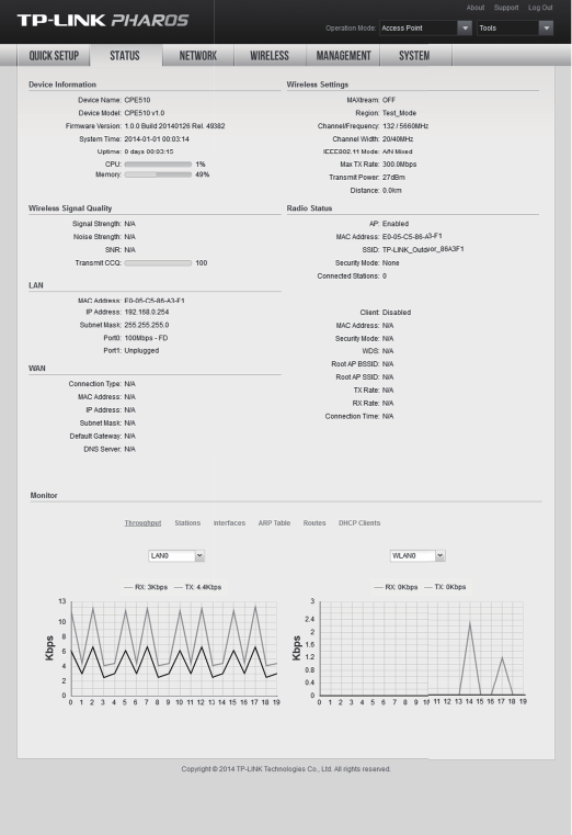
5. Then you will log in to the PharOS Web Interface and see the Status
page, shown as the gure below.
14
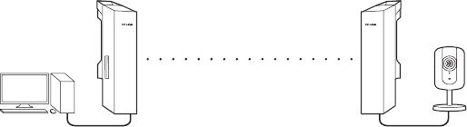
• Point-to-Point
Point-to-Point application is used to build a transparent bridge
between two locations which are far from each other. The gure shown
below is an example for this application.
Refer to the following steps to congure the CPEs.
2. Conguration for Typical Application
This section introduces the congurations for the Point-to-Point
application.
Congure the Access Point
1. Log in to PharOS
2. Go to the Quick Setup page
3. Operation Mode
• Select 'Access Point'
• Click 'Next'
4. LAN Settings: Click 'Next'
5. Wireless AP Settings
• SSID: customize the name for the network as you like
• Security: select 'WPA-PSK/WPA2-PSK'
• PSK Password: create the password for the network as you like
• Distance Setting: enter the distance between the Access Point and
the Client. It is recommended to round the number up to the
nearest integer
• Select the MAXtream option if the Access Point and the Client
both are Pharos outdoor CPEs. (Refer to Q4 in FAQ for details about
MAXtream)
• Click 'Next'
6. Finsh: Click 'Finish'
IP camera
Access Point
LAN: 192.168.0.254
Client
LAN: 192.168.0.2
Computer
15
Congure the Client
1. Log in to PharOS
2. Go to the Quick Setup page
3. Operation Mode
• Select 'Client'
• Click 'Next'
4. LAN Settings
• IP Address: 192.168.0.2 (on the same subnet with the Access Point)
• Click 'Next'
5. Wireless Client Settings
• SSID of Remote AP: click 'Survey', select the SSID of the Access Point,
and click 'Connect'
• Security: select 'WPA-PSK/WPA2-PSK'
• PSK Password: enter the password of the Access Point
• Distance Setting: enter the same number with the Access Point
• Click 'Next'
6. Finsh: Click 'Finish'
16
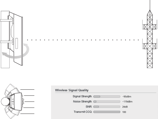
Antenna Alignment
In order to get the best performance, you can precisely align the
direction of the CPE with the assistance of 'Wireless Signal Quality' on
STATUS page of the Pharos Web Interface.
24dB
22dB
18dB
22dB
18dB
WISP
Adjust the direction of the CPE until the device reaches the highest SNR

17
HARDWARE FEATURES
Dimensions CPE520/CPE220: 275.83*79*60.3mm
CPE510/CPE210: 224.34*79*60.3mm
Interface
LAN0: 10/100Mbps Ethernet Port(PoE IN)
LAN1: 10/100Mbps Ethernet Port
GND: Grounding Terminal for Lightning Protection
RESET: Button to restore the device to Factory Default
Power Supply 24V Passive PoE Adapter Included
ESD Protection1) 15kV
Lightning Protection1) 6kV
Operating
Temperature
-30℃~60℃ (-22℉~158℉)
Operating Humidity 5% ~ 95 %
Certication CE, FCC, RoHS, IPX5
WIRELESS FEATURES
Models CPE210 CPE220 CPE510 CPE520
Antenna Gain 9dBi 12dBi 13dBi 16dBi
Horizontal Beamwidth/
Elevation Beamwidth2)
65°/ 45° 45°/ 30° 45°/ 33° 50°/ 20°
Maximum Transmit
Power3)
27dBm 30dBma 27dBm 30dBm
Operating
Frequency
2.4-
2.4835GHz
2.4-
2.4835GHz
5.15-
5.85GHz
5.15-
5.85GHz
802.11 Standards 11b/g/n 11b/g/n 11a/n 11a/n
Specications
1) Estimation is based on copper grounding cable and shielded CAT5e cable with ESD drain wire.
2) Beamwidth values may vary throughout operating frequency.
3) Maximum transmit power and operating frequency may vary in dierent countries or regions.
Note
18
Frequently Asked
Questions (FAQ)
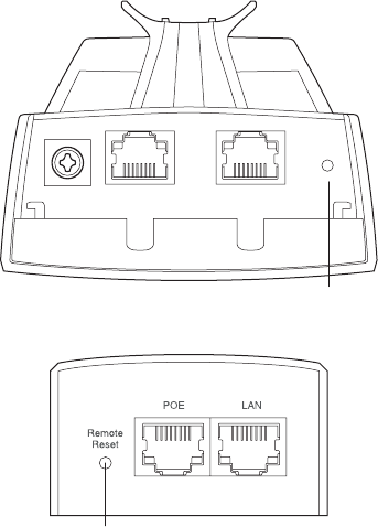
Q1. How to restore the CPE to its factory
default settings?
With the CPE powered on, press and hold the 'RESET' button of the
CPE or the 'Remote Reset' button of the Passive PoE Adapter for about
8 seconds until the Wireless Signal Strength LEDs ash.
RESET
Remote
Reset
Pharos CPE:
Passive PoE Adapter:
19
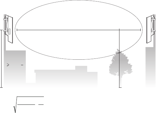
Q2. How to calculate the minimum
mounting height of the devices?
In order to maximize the received signal strength of the devices,
installers need to minimize the eect of the out-of-phase signals,
which is caused by obstacles in the path between the transmitter and
the receiver. Fresnel Zone is a usual method to calculate this path, as
shown in the formula and the gure below.
where,
r = Fresnel zone radius in meters
c = 3x10⁸ m/s, speed of light
f = operating frequency of the devices in Hz
d1 & d2 = the distances between the point
and the devices in meters
h = the height of
obstacle at this point
H h+r*(1 40%)
(H is the height of the CPE)
For example, assume d1 is 2km, d2 is 8km, and f is 2.4GHz, then r
would be 14.142m. Considering a toleration of 40%, allowable radius
would be 8.485m. Assume h is 10m, then the result of the minimum
mounting height based on this point would be 18.485m. Similarly,
calculate the results based on all the points where there are obstacles,
and the maximum value would be the nal result.
For more information, please refer to
http://en.wikipedia.org/wiki/Fresnel_zone
f
c
dd
dd
r⋅
+
×
=
21
21
d2
r
d1
20
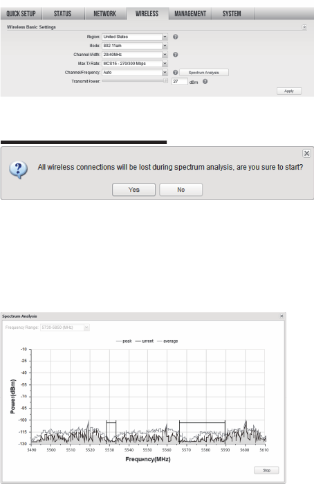
Q3. How can I use Spectrum Analysis
to nd the appropriate channel for the
devices?
1. Log in to PharOS, on the 'WIRELESS' page, you can nd the 'Spectrum
Analysis' button as shown in the gure below. Click the button.
2. The following window will pop up. Click 'Yes' and you will then get
into the Spectrum Analysis page.
3. Select the 'Frequency Range' and click the 'Start' button, the PharOS
will begin to analyze the power of the frequency. Watch the curves
for a period of time, and then click 'Stop'. Mark the relatively low and
continuous part of the average curve, and note the corresponding
frequency range.
Here we take the gure below as an example.
into the Spectrum Analysis page.
into the Spectrum Analysis page. into the Spectrum Analysis page.
21
4. Close the Spectrum Analysis Window, and then you will get
back to the Wireless page. For the Channel/Frequency option, it is
recommended to select a value whose frequency is within the noted
frequency range.
So, in this example, the recommended Channel/Frequency is
116/5580MHz.
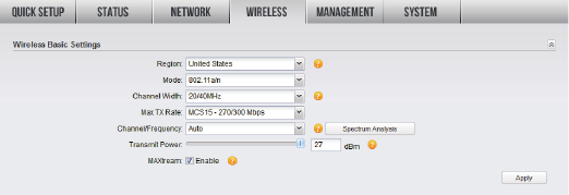
Q4. What is Pharos MAXtream?
Pharos MAXtream is a proprietary protocol developed on the basis of
Time Division Multiple Access (TDMA) by TP-LINK.
The MAXtream technology has the following advantages:
• Eliminates hidden node collisions & improves channel effi ciency.
• Lower latency, higher throughput, larger network capacity & more
stability.
To enable the MAXtream function among the AP and stations, you only
need to select the MAXtream option on the 'WIRELESS' page of the
PharOS Web Interface of the AP, shown as the gure below. Then the
stations will automatically adjust their connections to the AP.
Pharos MAXtream is a non-standard Wi-Fi protocol that is only
compatible with TP-LINK’s Pharos series products. Please notice that
you will not be able to connect other Wi-Fi devices to an AP with
MAXtream enabled.

FCC STATEMENT
CE Mark Warning
This equipment has been tested and found to comply with the limits for a Class B digital device,
pursuant to part 15 of the FCC Rules. These limits are designed to provide reasonable protection
against harmful interference in a residential installation. This equipment generates, uses and can
radiate radio frequency energy and, if not installed and used in accordance with the instructions,
may cause harmful interference to radio communications. However, there is no guarantee that
interference will not occur in a particular installation. If this equipment does cause harmful
interference to radio or television reception, which can be determined by turning the equipment
o and on, the user is encouraged to try to correct the interference by one or more of the following
measures:
• Reorient or relocate the receiving antenna.
• Increase the separation between the equipment and receiver.
• Connect the equipment into an outlet on a circuit dierent from that to which the receiver is
connected.
• Consult the dealer or an experienced radio/ TV technician for help.
This device complies with part 15 of the FCC Rules. Operation is subject to the following two
conditions:
1. This device may not cause harmful interference.
2. This device must accept any interference received, including interference that may cause
undesired operation.
Any changes or modications not expressly approved by the party responsible for compliance could
void the user’s authority to operate the equipment.
Note: The manufacturer is not responsible for any radio or TV interference caused by unauthorized
modications to this equipment. Such modications could void the user’s authority to operate the
equipment.
This is a class B product. In a domestic environment, this product may cause radio interference, in
which case the user may be required to take adequate measures.
FCC RF Radiation Exposure Statement:
This equipment complies with FCC RF radiation exposure limits set forth for an uncontrolled
environment. This device and its antenna must not be co-located or operating in conjunction with
any other antenna or transmitter.
“To comply with FCC RF exposure compliance requirements, this grant is applicable to only Mobile
Congurations. The antennas used for this transmitter must be installed to provide a separation
distance of at least 20cm from all persons and must not be co-located or operating in conjunction
with any other antenna or transmitter.”
Limited to local law of the United States, selecting country code and channel function was disabled.
The permitted channel&power is controlled by wireless driver.The end-user have no permission and
no way to change it. That is to say that The device can only work in legal channel&power.

Canadian Compliance Statement
This product can be used in the following countries:
AT / BG / BY / CA / CZ / DE / DK / EE / ES / FI / FR / GB / GR / HU / IE / IT
LT / LV / MT / NL / NO / PL / PT / RO / RU / SE / SK / TR / UA
This device complies with Industry Canada license-exempt RSS standard(s). Operation is subject to
the following two conditions:
(1) This device may not cause interference, and
(2)This device must accept any interference, including interference that may cause undesired
operation of the device.
Cet appareil est conforme aux norms CNR exemptes de licence d’Industrie Canada. Le
fonctionnement est soumis aux deux conditions suivantes:
(1) cet appareil ne doit pas provoquer d’interférences et
(2) cet appareil doit accepter toute interférence, y compris celles susceptibles de provoquer un
fonctionnement non souhaité de l’appareil.
Продукт сертифіковано згідно с правилами системи УкрСЕПРО на відповідність вимогам
нормативних документів та вимогам, що передбачені чинними законодавчими актами України.
Industry Canada Statement
Complies with the Canadian ICES-003 Class B specications.
Cet appareil numérique de la classe B est conforme à la norme NMB-003 du Canada.
This device complies with RSS 210 of Industry Canada. This Class B device meets all the requirements
of the Canadian interference-causing equipment regulations.
Cet appareil numérique de la Classe B respecte toutes les exigences du Règlement sur le matériel
brouilleur du Canada.
Safety Information
• When product has power button, the power button is one of the way to shut o the product;
When there is no power button, the only way to completely shut o power is to disconnect the
product or the power adapter from the power source.
• Don’t disassemble the product, or make repairs yourself. You run the risk of electric shock and
voiding the limited warranty. If you need service, please contact us.
• Avoid water and wet locations.

COPYRIGHT & TRADEMARKS
Specications are subject to change without notice.
is a registered trademark of TP-LINK TECHNOLOGIES CO., LTD. Other brands
and product names are trademarks or registered trademarks of their respective holders.
No part of the specications may be reproduced in any form or by any means or
used to make any derivative such as translation, transformation, or adaptation
without permission from TP-LINK TECHNOLOGIES CO., LTD. Copyright © 2014 TP-LINK
TECHNOLOGIES CO., LTD. All rights reserved.
Website: http://www.tp-link.com
Tel: +86 755 26504400
E-mail: support@tp-link.com
7106504648 REV1.0.0