TP Link Technologies CPE610V1 5GHz 300Mbps 23dBi Outdoor CPE User Manual Part 1
TP-Link Technologies Co., Ltd. 5GHz 300Mbps 23dBi Outdoor CPE Part 1
Contents
- 1. User Manual Part 1
- 2. User Manual Part 2
User Manual Part 1

CPE610
Outdoor CPE
Installation Guide

Contents
Overview
Package Contents
Hardware Overview
Hardware Connection
Site Consideration
Hardware Installation
Power Supply
Lightning & ESD Protection
Software Configuration
Logging in to the PharOS
Configuration for a Typical Application
Antenna Alignment
Specifications
FAQ
1
4
15
18
19
20
TP-Link's Pharos series outdoor CPEs are dedicated to outdoor
wireless network solutions. This guide is applicable to the product
CPE610.
Overview
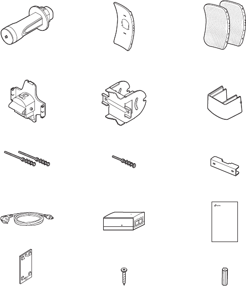
Package Contents
1
Power Cord Passive PoE Adapter
Installation Guide
CPE610
Installation Guide
Outdoor CPE
Pharos CPE Center Reflector Panel Side Reflector Panels
(Qty.2)
Bolts with Nut and Lock
Washer Assemblies
(M6×110, Qty.2)
Bolts with Nut and Lock
Washer Assemblies
(M6×70)
Rear Cover Mounting Bracket
(For CPE)
Pole-mount Clamp
ST3×10 Self-tapping Screws
(Qty.2)
D3×28 Plastic Wall Anchors
(Qty.2)
Mounting Bracket
(For PoE Adapter)
Protective Cap
Bottom View
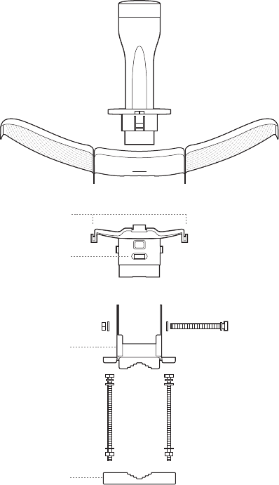
Hardware Overview
2
Reflector Assembly
Securing Arms
Bubble Level
Mounting Bracket
Pole-mount Clamp
Rear Cover
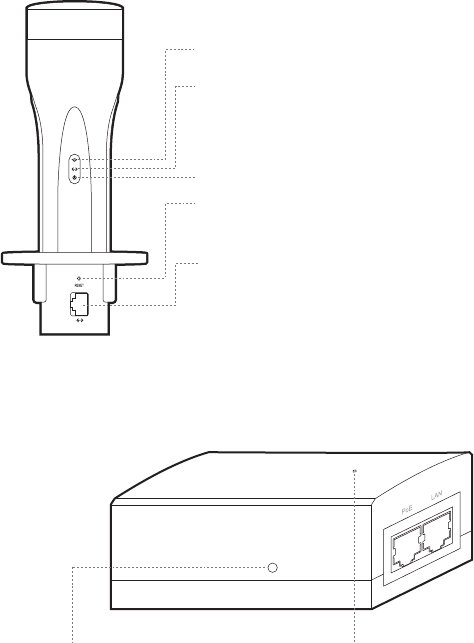
3
On: A device is connected to this port, but there
is no activity.
Flashing: A device is connected to this port, and
is active.
On: The CPE is powered on.
Panel Layout
On: The wireless function is enabled.
Passive PoE Adapter
Power LED
On: Power on.
Off: Power off.
Remote Reset
Press and hold for 5 seconds to reset the CPE
to its factory defaults.
RESET
Press and hold for 5 seconds to reset the CPE to
its factory defaults.
ETHERNET
The port is to connect to the POE port of the
provided PoE adapter for both data transmission
and power supply through Ethernet cabling.
4
Hardware Connection
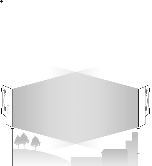
Site Consideration
Ensure a clear line of sight between the wireless devices for
optimum performance. An elevated location is recommended as
obstacles like trees, buildings and large steel structures will
weaken the wireless signal. See 'Q2' in 'FAQ' for details about
how to calculate the minimum mounting height of the devices.
Mounting Height
Line of Sight
Side View
5
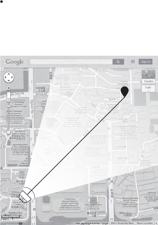
Orientation
Install the CPE devices so that they point towards the devices
that will receive the signal. You can orient the devices with the
help of Google Maps, GPS and some landmarks. The horizontal
bandwidth of CPE610 is 6.8°.
A
shenzhen
B
Line of Sight
Horizontal
Beamwidth
6
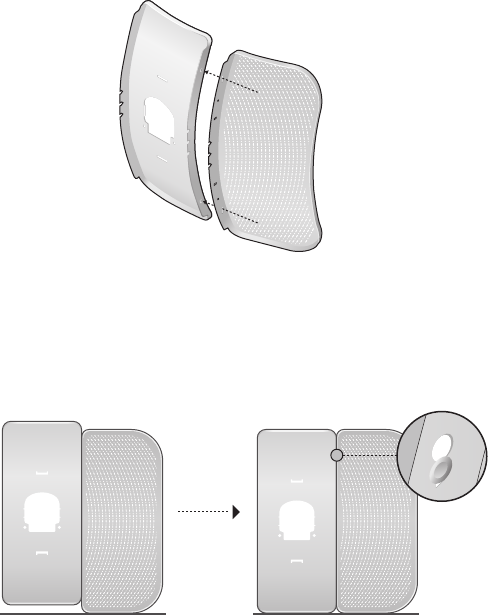
1. Attach the Side Reflector Panels to the Center Reflector Panel
as follows:
a. Insert the two mounting studs on the Center Reflector
Panel into the large opening of the slots on the Side
Reflector Panel.
b. Slide the Side Reflector Panel until the mounting studs are
positioned over the narrow opening of the slots, and the top
edges of the panels should be aligned when done.
Hardware Installation
7
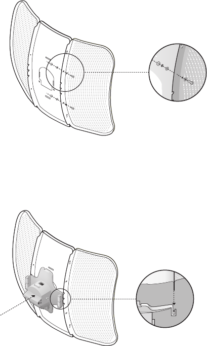
c. Repeat step a and step b to attach the other Side Reflector
Panel.
d. (Optional) Attach the Side Reflector Panels to the Center
Reflector Panel more securely using four M2.5x8 bolts and
nuts (not provided). This is recommended if the CPE device
is exposed to extreme weather, such as strong winds.
2. Attach the Rear Cover to the reflector assembly as follows:
a. While holding the reflector assembly, align the raised edges
on the back with the Securing Arms of the Rear Cover, and
align the Snap Hooks on the Rear Cover with the slots on
the Center Reflector Panel.
8
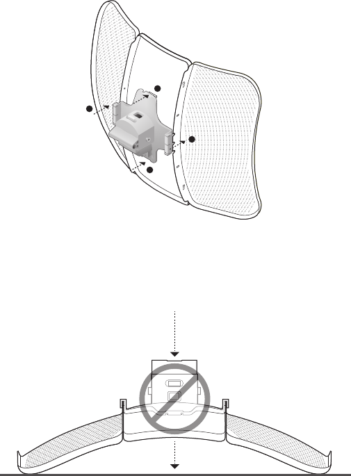
b. Attach the Rear Cover to the reflector assembly. Press upon
the Rear Cover at the four positions marked in the diagram
below in sequence until it locks into place.
WARNING: To avoid damage, do not place the panels on a flat
surface or push down on it.
1
2
4
3