TP Link Technologies CPE610V2 5GHz 300Mbps 23dBi Outdoor CPE User Manual 5 User Manual rev1
TP-Link Technologies Co., Ltd. 5GHz 300Mbps 23dBi Outdoor CPE 5 User Manual rev1
5. User Manual rev1

CPE610
5GHz 300Mbps 23dBi Outdoor CPE
Installation Guide

Contents
Overview
Package Contents
Hardware Overview
Hardware Connection
Site Consideration
Application Example
Hardware Installation
Power Supply
Lightning & ESD Protection
Installer Compliance Responsibility
Software Configuration
Logging in to the PharOS
Configuration for a Typical Application
Antenna Alignment
Specifications
FAQ
1
4
20
21
22
17
TP-Link's Pharos series outdoor CPEs are dedicated to outdoor
wireless network solutions. This guide is applicable to the product
CPE610.
Overview
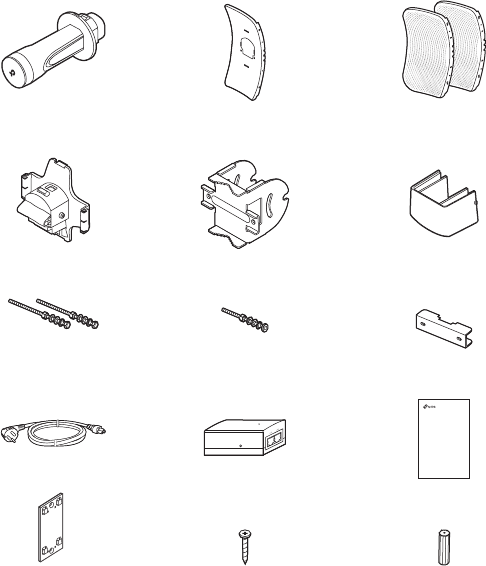
Package Contents
1
Power Cord Passive PoE Adapter
Installation Guide
CPE610
Installation Guide
Outdoor CPE
Pharos CPE Center Reflector Panel Side Reflector Panels
(Qty.2)
Bolts with Nut and Lock
Washer Assemblies
(M6×110, Qty.2)
Bolts with Nut and Lock
Washer Assemblies
(M6×70)
Rear Cover Mounting Bracket
(For CPE)
Pole-mount Clamp
ST3×16 Self-tapping Screws
(Qty.2)
D3×28 Plastic Wall Anchors
(Qty.2)
Mounting Bracket
(For PoE Adapter)
Protective Cap
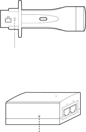
Bottom View
Hardware Overview
2
Reflector Assembly
Securing Arms
Bubble Level
Mounting Bracket
Pole-mount Clamp
Rear Cover
3
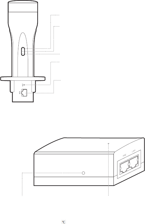
On: A device is connected to the ETHERNET port,
but there is no activity.
Flashing: A device is connected to the
ETHERNET port and is active.
On: The CPE is powered on.
Panel Layout
On: The wireless function is enabled.
Passive PoE Adapter
Power LED
On: Power on.
Off: Power off.
Remote Reset
Press and hold for 5 seconds to reset the CPE
to its factory defaults.
RESET
Press and hold for 5 seconds to reset the CPE to
its factory defaults.
ETHERNET
The port is used to connect to the POE port of
the provided PoE adapter for both data
transmission and power supply through Ethernet
cabling.
Attention:The Adapter which works at 0-40 shall be installed and placed in an indoor environment.
4
Hardware Connection
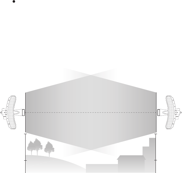
Site Consideration
Ensure a clear line of sight between the wireless devices for
optimum performance. An elevated location is recommended as
obstacles like trees, buildings and large steel structures will
weaken the wireless signal. See 'Q2' in 'FAQ' for details about
how to calculate the minimum mounting height of the devices.
Mounting Height
Line of Sight
Side View
5
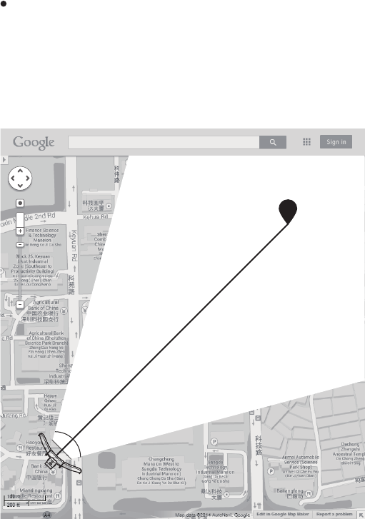
Orientation
Install the CPE devices so that they point towards the devices
that will receive the signal. You can orient the devices with the
help of Google Maps, GPS and some landmarks. The horizontal
bandwidth of CPE610 is 7°.
A
shenzhen
B
Line of Sight
Horizontal
Beamwidth
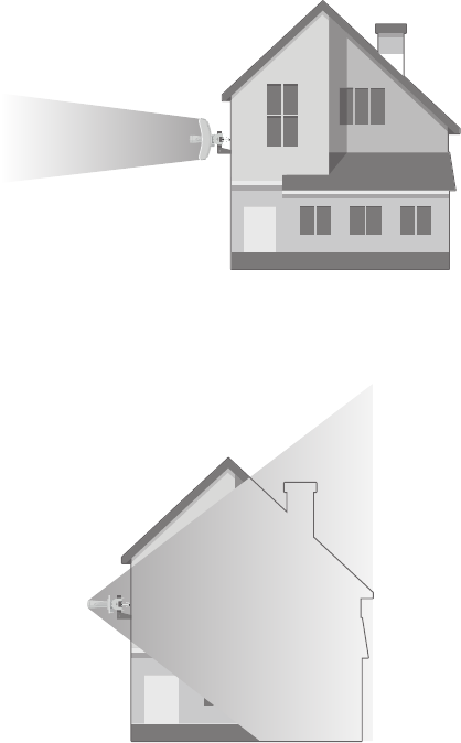
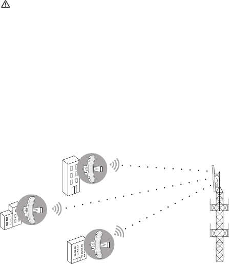
Application Example
The CPE device with the reflector installed provides outdoor
network access over long distances for point-to-point
applications.
The CPE device without the reflector installed provides outdoor
-to-indoor Wi-Fi coverage with the Feed only mode.
6
7
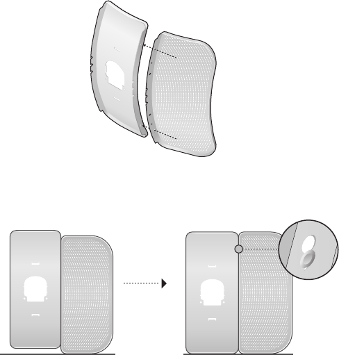
1. Attach the Side Reflector Panels to the Center Reflector Panel
as follows:
a. Insert the two mounting studs on the Center Reflector
Panel into the large opening of the slots on the Side
Reflector Panel.
b. Slide the Side Reflector Panel until the mounting studs are
positioned over the narrow opening of the slots, and the top
edges of the panels should be aligned when done.
Hardware Installation
TERMS OF USE:
Installers must abide by
local rules and regulations in terms of legal frequency channels,
output power, and Dynamic Frequency Selection (DFS)
requirements.
8
c. Repeat step a and step b to attach the other Side Reflector
Panel.
d. (Optional) Attach the Side Reflector Panels to the Center
Reflector Panel more securely using four M2.5x8 bolts and
nuts (not provided). This is recommended if the CPE device
is exposed to extreme weather, such as strong winds.
2. Attach the Rear Cover to the reflector assembly as follows:
a. While holding the reflector assembly, align the raised edges
on the back with the Securing Arms of the Rear Cover, and
align the Snap Hooks on the Rear Cover with the slots on
the Center Reflector Panel.
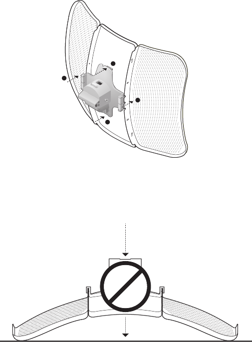
9
b. Attach the Rear Cover to the reflector assembly. Press upon
the Rear Cover at the four positions marked in the diagram
below in sequence until it locks into place.
WARNING: To avoid damage, do not place the panels on a flat
surface or push down on it.
1
2
4
3
10
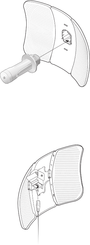
3. Insert the Pharos CPE into the Rear Cover until the CPE locks
into place.
4. Connect the Ethernet cable to the Pharos CPE.
a. Connect the Ethernet cable to the Ethernet port.
Note: The length of the Ethernet cable is up to 60m for steady
power supply.
11
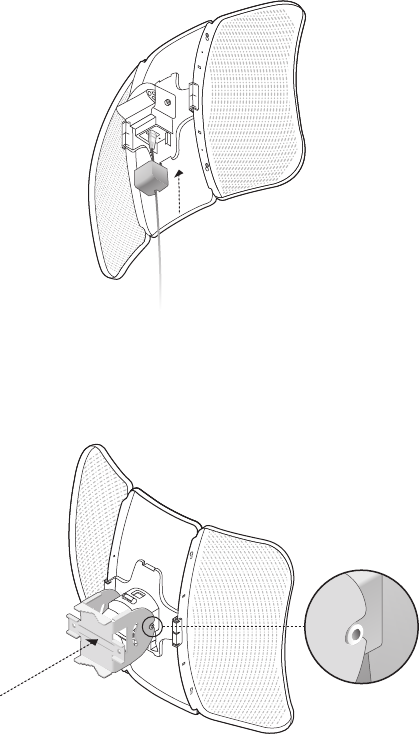
b. Attach the Protective Cap to the Rear Cover.
5. Attach the Mounting Bracket to the Rear Cover until the
grooves on the Mounting Bracket are positioned over the pins
on the Rear Cover.
12
6. Secure the Mounting Bracket to the Rear Cover using M6x70
Bolts with Nut and Lock Washer Assemblies.
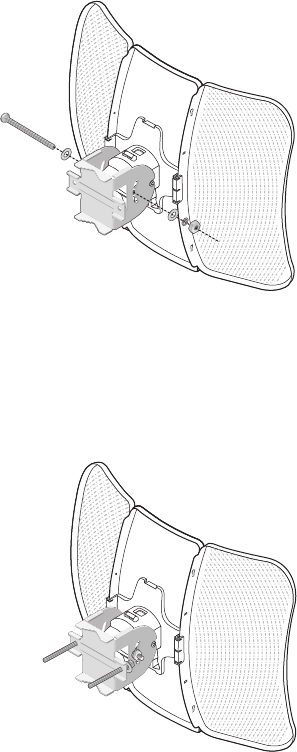
7. Attach the CPE assembly to the pole using two Pole-mount
Clamps and two M6x110 Bolts with Nut and Lock Washer
Assemblies.
a. Insert the two Bolts into the Mounting Bracket.
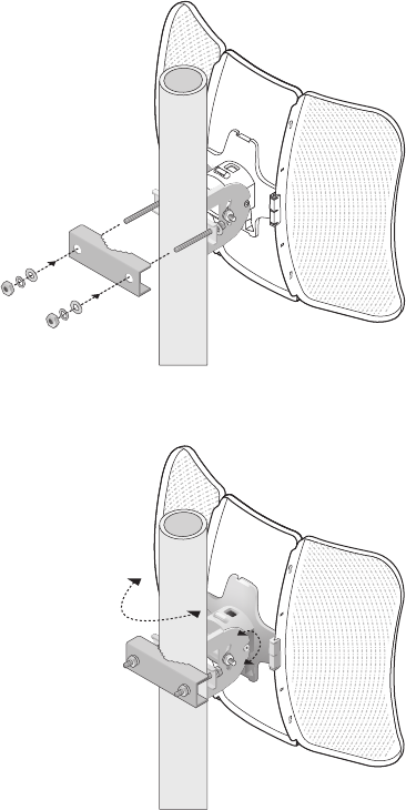
13
b. Secure the Pole-mount Clamps with Nuts and Washers.
Note: Suitable pole diameters range from 15mm to 70mm.
8. Adjust the azimuth and elevation angle of the CPE device to
achieve maximum signal strength.
14
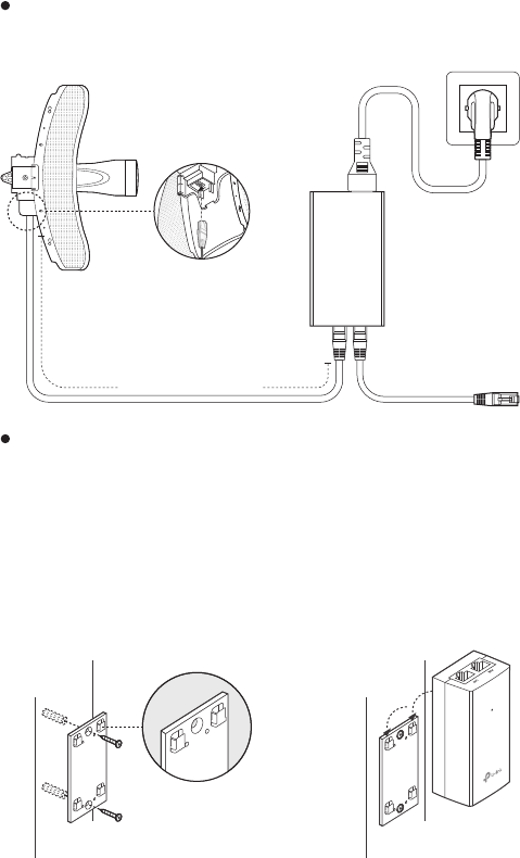
Power Supply
Connecting the PoE Adapter
Connect the devices as shown in the figure below.
PoE LAN
Ethernet cable
length up to 60m
Mounting the PoE Adapter (Optional)
Note: To ensure the passive PoE adapter is attached most securely, it is
recommended to install the adapter with the Ethernet port facing upward.
1. Drill two holes on the wall
and insert the plastic wall
anchors into the the holes.
Secure the mounting bracket
to the wall.
2. Attach the passive PoE
adapter to the mounting
bracket by sliding the adapter
in the direction of the arrows
until it locks into place.
15
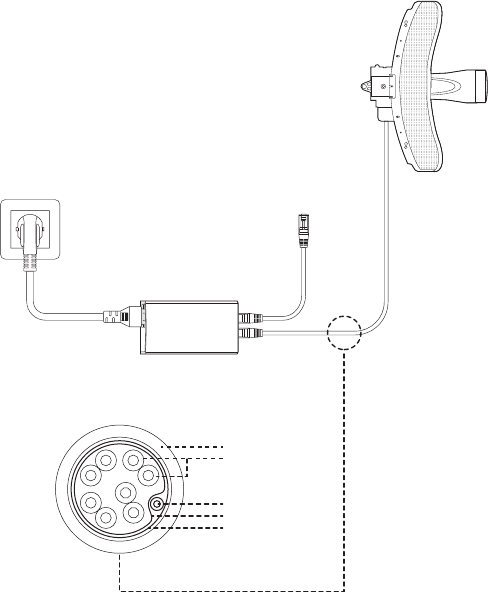
Lightning & ESD Protection
Proper grounding is extremely important for outdoor devices.
By using shielded CAT5e (or above) cable with ground wire and
the provided PoE adapter, you can effectively eliminate ESD
attacks.
CPE
PoE Adapter with
Earth Ground
Shielded CAT5e (or above)
Cable with Ground Wire
Grounded 3-wire
Power Outlet
Twisted Pair
Ground Wire
Secondary Cable Shield
Cable Shield
Sheath
Installer Compliance Responsibility
Devices must be professionally installed and it is the
professional installer's responsibility to make sure the device is
operated within local rules and regulations.
Since TP-Link’s Pharos outdoor CPE610 can be paired with a
variety of antennas, the Antenna and Transmit
Power fields are provided to the professional installer to assist
in meeting regulatory requirements.
Refer to Antenna and Transmit Power elds to make sure the devices are
operated within local rules and regulations.
16
17
Open a web browser, type http://192.168.0.254 into the
address field and press Enter (Windows) or return (Mac). It is
recommended to use the latest version of Google Chrome,
Firefox or Safari.
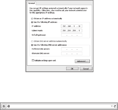
Software Conguration
Logging in to the PharOS
Before accessing the PharOS Web Interface, you need to
assign a static IP address 192.168.0.X (X ranges between 2
and 253, e.g. 192.168.0.10) to your computer.
This chapter introduces the login to the PharOS Web Interface
and the software configurations.
1.
2.
192.168.0.254
Enter admin for both User Name and Password, then select
the Language from the drop-down list. Read and agree to the
terms of use, then click Login.
3.
18
Change
the
default
User
Name
and
Password
for security
purposes. You can then start to configure your CPE.
1. Log in to PharOS and go to the Quick Setup page.
2. Operation Mode: Select Access Point and click Next.
3. LAN Settings: Click Next.
4. Wireless AP Settings:
a. Create a new SSID (Network name) for your wireless
network.
b. Select WPA-PSK/WPA2-PSK for the Security method and
create a PSK Password to protect your AP.
Congure the Access Point (AP)
For subsequent logins, use the new username and password.
Conguration for a Typical Application
The typical topology is as follows: Multiple wireless bridges are
built among the access point and the clients. Follow the
instructions below to configure the Access Point and the Client.
For simplicity, we will take one wireless bridge as an example.
4.
For more configurations, please visit
https://www.tp-link.com/support to download the User Guide of
PharOS products in the download center.
Access Point
Client
Client
Client
19
Congure the Client
1. Log in to PharOS and go to the Quick Setup page.
2. Operation Mode: Select Client and click Next.
3. LAN Settings: Change the IP Address to 192.168.0.X (X
ranges between 2 and 253), the same subnet as the access
point, and click Next.
4. Wireless Client Settings:
a. Click Survey and select the SSID of the Access Point in
the AP list, then click Connect.
b. Select WPA-PSK/WPA2-PSK from the Security option,
enter the same PSK password and distance value of the
Access Point, then click Next.
5. Finish: Verify your settings and click Finish to complete the
configuration.
For more configurations, please visit
https://www.tp-link.com/support to download the User Guide of
PharOS products in the download center.
c. Enter the distance between the Access Point and the
Client into the Distance Setting field.
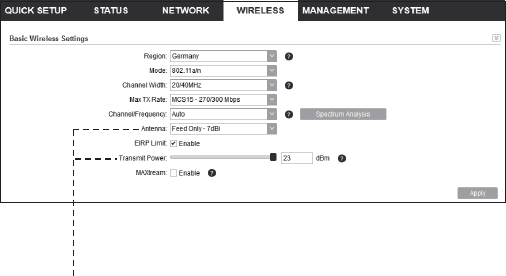
d. Select the MAXtream checkbox (Refer to Q3 in FAQ for
details about MAXtream), and click Next.
5. Finish: Verify your settings and click Finish to complete the
configuration.

20
Antenna Alignment
In order to get the best performance, you can precisely align the
direction of the CPE with the assistance of Wireless Signal
Quality on the STATUS page of the PharOS Web Interface.
Adjust the direction of the CPE until the
SNR reaches a maximum.
WBS+Antenna
WBS+Antenna

21
Specications
Interface
Power Supply
1
1
ESD Protection
Lightning Protection
Operating Humidity
Operating Temperature
Certication
10/100Mbps Ethernet port
24V passive PoE adapter included
15KV
Up to 6KV
-40 to 70 (-40 to 158
)
℉
℉
10% to 90%
CE, FCC, RoHS, IP65
℃℃
Note:
1. Estimation is based on shielded CAT5e(or above) cable with an
integrated grounding wire.
HARDWARE FEATURES
WIRELESS FEATURES
802.11 Standards 11a/n
Button RESET: Restore the device to its factory
defaults
22
FAQ
How to restore the CPE to its factory default settings?
With the CPE powered on, press and hold the RESET
button on the CPE for about 5 seconds.
Q1.
Method 1:
Method 2:
RESET Button:
Press & hold for about 5 seconds
Remote Reset Button:
Press & hold for about 5 seconds
With the CPE powered on, press and hold the Remote
Reset button on the passive PoE adapter for about 5
seconds.
23
How to calculate the minimum mounting height
of the devices?
In order to maximize the received signal strength of the
devices, you need to minimize the effect of the
out-of-phase signals, which is caused by obstacles in the
path between the transmitter and the receiver. Fresnel
Zone is a usual method to calculate this path, as shown in
the formula and the figure below.
Q2.
h = the height of
obstacle at this point
H h+r*(1 40%)
(H is the height of the CPE)
d2
r
d1
where,
r = Fresnel zone radius in meters
c = 3x10⁸ m/s, speed of light
f = operating frequency of the
devices in Hz
d1 & d2 = the distances between the
point and the devices in meters
For example, assume d1 is 2km, d2 is 8km, and f is 2.4GHz,
then r would be 14.142m. Considering a toleration of 40%,
allowable radius would be 8.485m. Assume h is 10m, then
the result of the minimum mounting height based on this
point would be 18.485m. Similarly, calculate the results
based on all the points where there are obstacles, and the
maximum value would be the final result.
For more information, please refer to:
http://en.wikipedia.org/wiki/Fresnel_zone
f
c
dd
dd
r⋅
+
×
=
21
21
24
What is Pharos MAXtream?
Pharos MAXtream is a proprietary protocol developed on
the basis of Time Division Multiple Access (TDMA) by
TP-Link.
The MAXtream technology has the following advantages:
Eliminates hidden node collisions & improves channel
efficiency.
Lower latency, higher throughput, larger network
capacity & more stability.
Improves the QoS for video, voice and sound data
stream.
By dividing the timing of transmission into different time
slots, MAXtream allows the Pharos devices to transmit in
rapid succession, one after another, each stream using its
own time slot to transmit and receive frames, which greatly
reduces the chance of collision.
Pharos MAXtream is a non-standard Wi-Fi protocol that is
only compatible with TP-Link’s Pharos series products.
Please note that you will not be able to connect other Wi-Fi
devices to an AP with MAXtream enabled.
Q3.
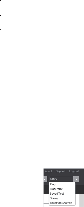
Log in to PharOS, click Spectrum Analysis in the tools
drop-down list,
a window will pop up to remind you that all
wireless connections
will be lost during spectrum analysis.
Click Yes to continue to the Spectrum Analysis page.
1.
How can I use Spectrum Analysis to find the
appropriate channel for the devices?
Q4.
25
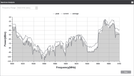
2.
Click Start, PharOS will begin to analyze the power of
frequency
. Observe the curves for a period of time, and
then click
Stop
. Note that the relatively low and continuous
part of the average curve indicates less radio noise. Here,
we use the figure below as an example.
3. When choosing channel/frequency, you should avoid the
spectrum with large radio noise. In this example, the
recommended channel/ frequency is 112/5560MHz.
FCC STATEMENT
FCC RF Radiation Exposure Statement
This equipment complies with FCC RF radiation exposure limits set forth for an
uncontrolled environment. This device and its antenna must not be co-located or
operating in conjunction with any other antenna or transmitter.
“To comply with FCC RF exposure compliance requirements, this grant is
applicable to only Mobile Configurations. The antennas used for this transmitter
must be installed to provide a separation distance of at least 20 cm from all
persons and must not be co-located or operating in conjunction with any other
antenna or transmitter.”
This equipment has been tested and found to comply with the limits for a Class A
digital device, pursuant to part 15 of the FCC Rules. These limits are designed to
provide reasonable protection against harmful interference when the equipment is
operated in a commercial environment. This equipment generates, uses, and can
radiate radio frequency energy and, if not installed and used in accordance with the
instruction manual, may cause harmful interference to radio communications.
Operation of this equipment in a residential area is likely to cause harmful
interference in which case the user will be required to correct the interference at
his own expense.
This device complies with part 15 of the FCC Rules. Operation is subject to the
following two conditions:
1) This device may not cause harmful interference.
2) This device must accept any interference received, including interference that
may cause undesired operation.
Any changes or modifications not expressly approved by the party responsible for
compliance could void the user’s authority to operate the equipment.
Note: The manufacturer is not responsible for any radio or TV interference caused
by unauthorized modifications to this equipment. Such modifications could void
the user’s authority to operate the equipment.
We, TP-Link USA Corporation, has determined that the equipment shown as above
has been shown to comply with the applicable technical standards, FCC part 15.
There is no unauthorized change is made in the equipment and the equipment is
properly maintained and operated. Issue Date: 2018/ 06/ 14

CE Mark Warning
This is a class A product. In a domestic environment, this product may cause radio
interference, in which case the user may be required to take adequate measures.
This device meets the EU requirements (2014/53/EU Article 3.1a) on the limitation
of exposure of the general public to electromagnetic fields by way of health
protection.
RF Exposure Information
EU declaration of conformity
TP-Link hereby declares that the device is in compliance with the essential
requirements and other relevant provisions of directives 2014/53/EU,
2009/125/EC and 2011/65/EU.
The original EU declaration of conformity may be found at http://ww-
w.tp-link.com/en/ce
RF Exposure Information
This device meets the EU requirements (2014/53/EU Article 3.1a) on the limitation
of exposure of the general public to electromagnetic fields by way of health
protection.
The device complies with RF specifications when the device used at 20 cm from
your body.
OPERATING FREQUENCY(the maxi-
mum transmitted power)
5470 MHz -5725 MHz (30dBm)
Safety Information
Keep the device away from water, fire, humidity or hot environments.
Do not attempt to disassemble, repair, or modify the device.
Do not use damaged charger or USB cable to charge the device.
Do not use any other chargers than those recommended.
Do not use the device where wireless devices are not allowed.
Adapter shall be installed near the equipment and shall be easily accessible.
Use only power supplies which are provided by manufacturer and in the
original packing of this product. If you have any questions, please don't hesitate to
contact us.
For EU/EFTA, this product can be used in the following countries:
AT / BE / BG / CH / CY / CZ / DE / DK / EE / EL / EF / FI / FR / HR / HU / IE / IS / IT / LI / LT /
LU / LV / MT / NL / NO / PL / PT / RO / SE / SI / SK / UK
•
•
•
•
•
•
DC voltage
Symbol Explanation
RECYCLING
This product bears the selective sorting symbol for Waste
electrical and electronic equipment (WEEE). This means that
this product must be handled pursuant to European
directive 2012/19/EU in order to be recycled or dismantled
to minimize its impact on the environment.
User has the choice to give his product to a competent
recycling organization or to the retailer when he buys a new
electrical or electronic equipment.
Explanation of the symbols on the product label
Продукт сертифіковано згідно с правилами системи УкрСЕПРО на відповідність вимогам
нормативних документів та вимогам, що передбачені чинними законодавчими актами
України.

© 2018 TP-Link 7106508090 REV1.0.2
The products of TP-Link partly contain software code developed by third parties, including
software code subject to the GNU General Public License (“GPL”). As applicable, the terms of the
GPL and any information on obtaining access to the respective GPL Code used in TP-Link
products are available to you in GPL-Code-Centre under (https://www.tp-link.com/en/support/g-
pl/). The respective programs are distributed WITHOUT ANY WARRANTY and are subject to the
copyrights of one or more authors. For details, see the GPL Code and other terms of the GPL.
For technical support, User Guide and other information, please visit
https://www.tp-link.com/support, or simply scan the QR code.