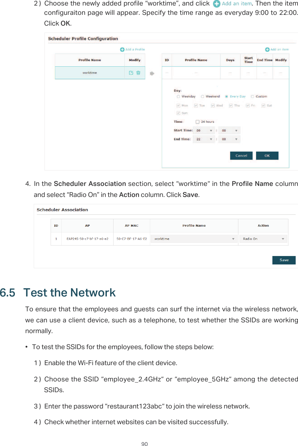
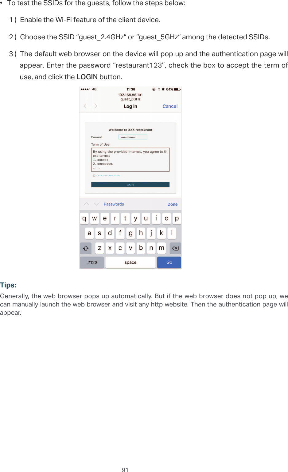
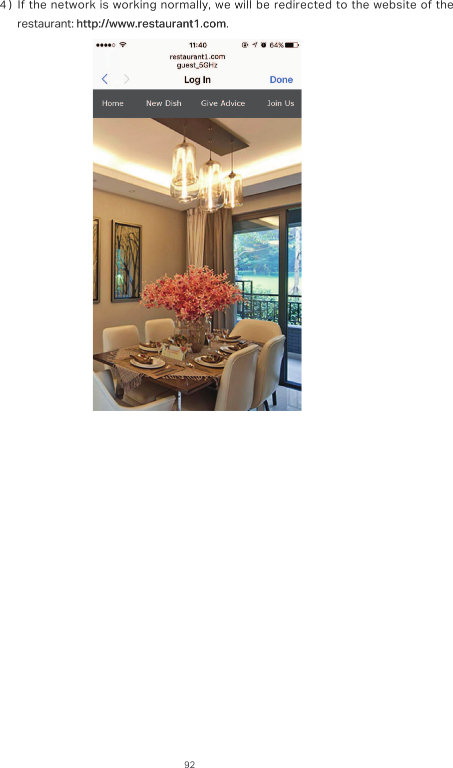
TP Link Technologies EAP110ODV3 300Mbps Wireless N Outdoor Access Point User Manual Rev 1
TP-Link Technologies Co., Ltd. 300Mbps Wireless N Outdoor Access Point Rev 1
UserManual.wiki
>
TP Link Technologies
>
EAP110ODV3 User Manual
user manual_Rev
Navigation menu
Upload a User Manual
Namespaces
Wiki Guide
HTML
PDF
Info
Views
User Manual
Discussion / Help
Navigation
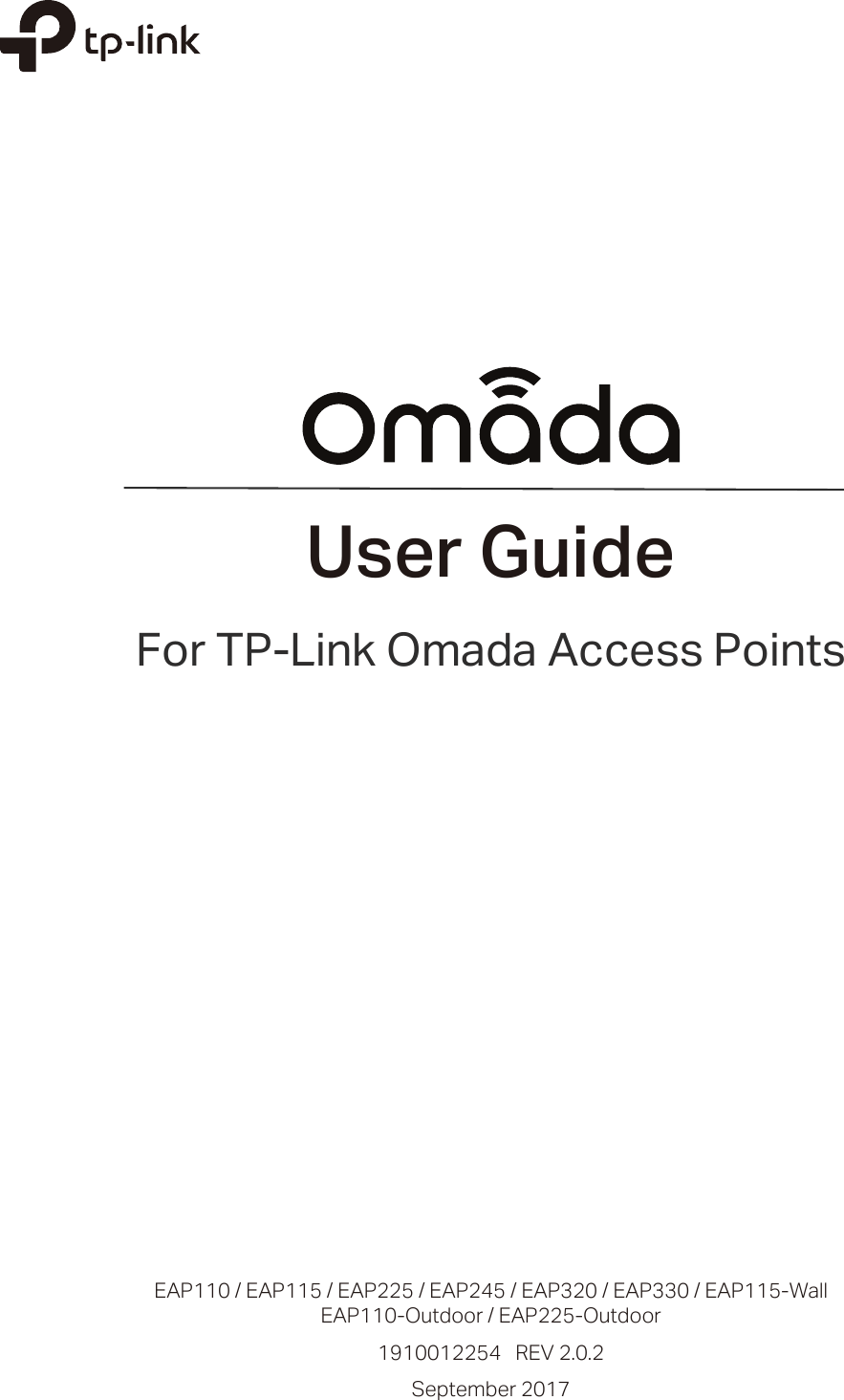
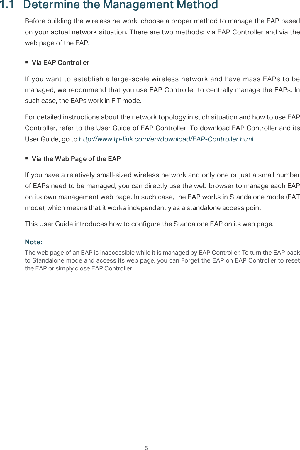
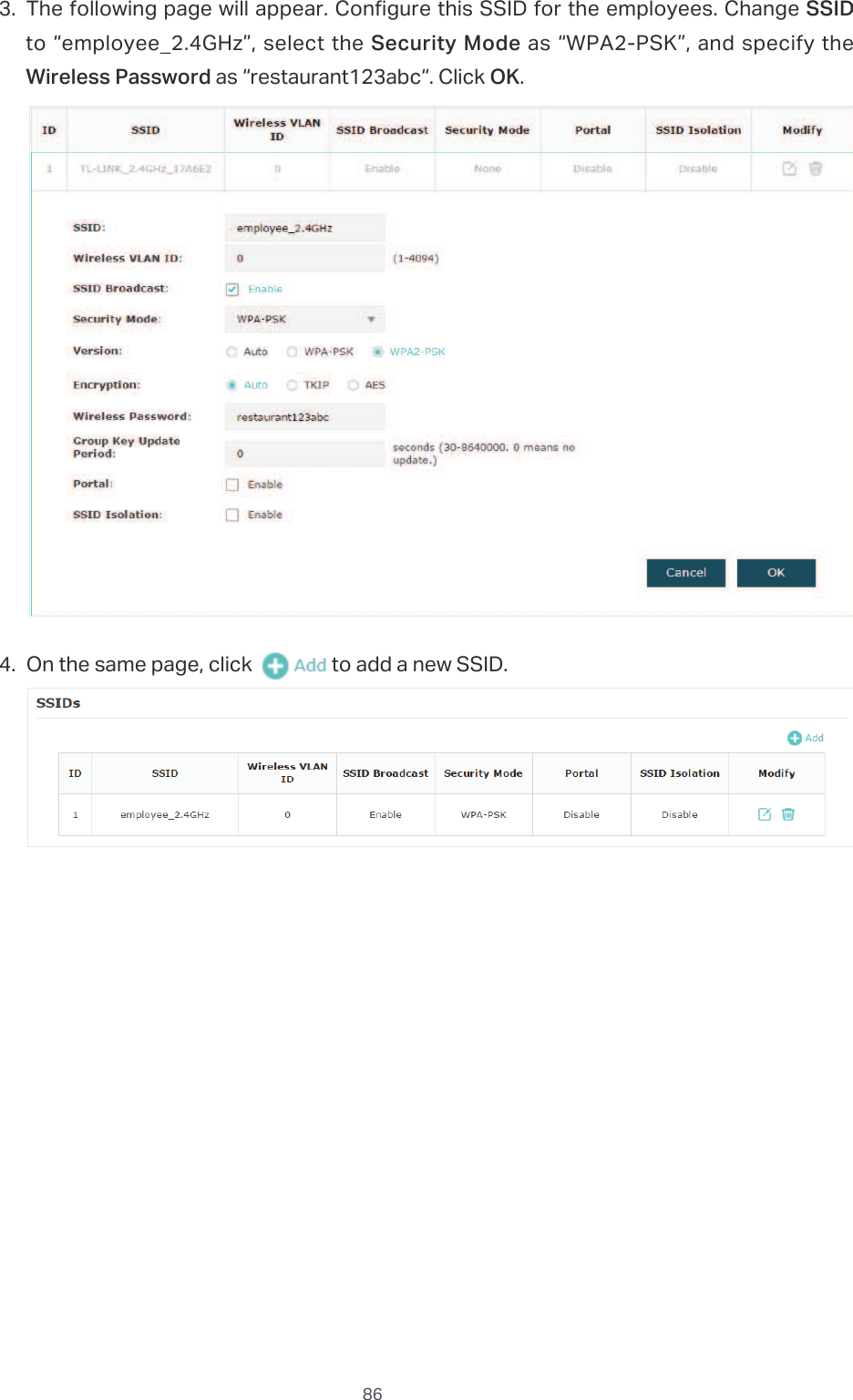
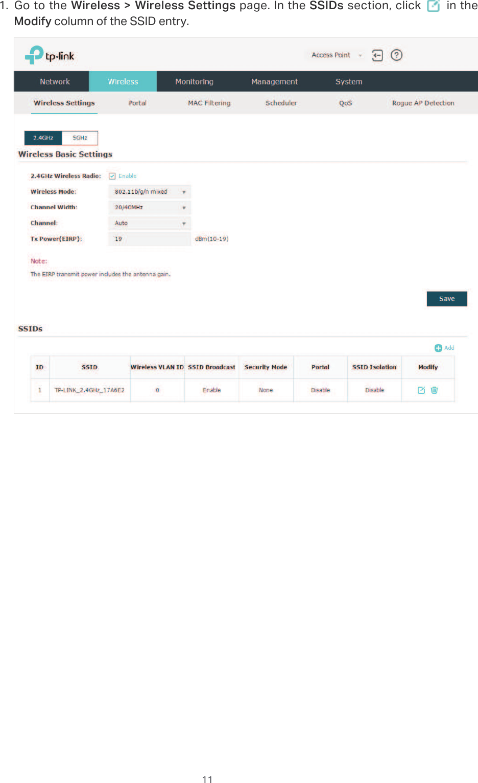
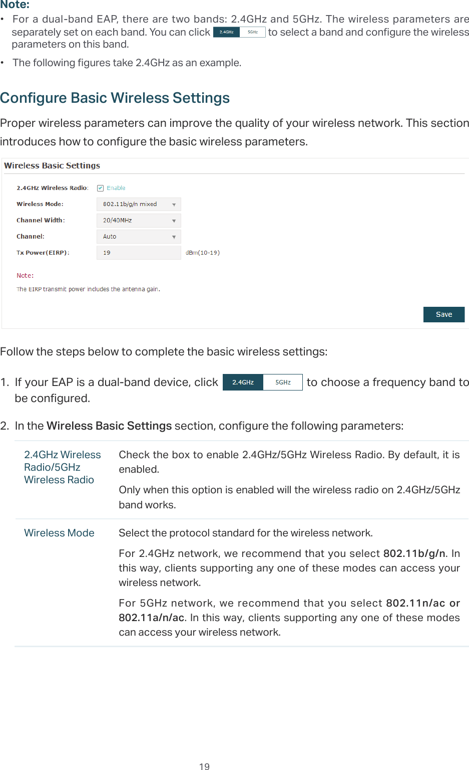
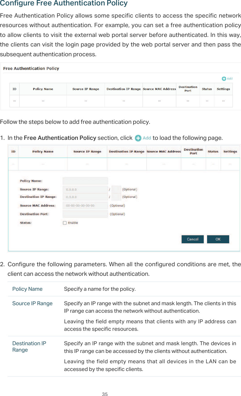
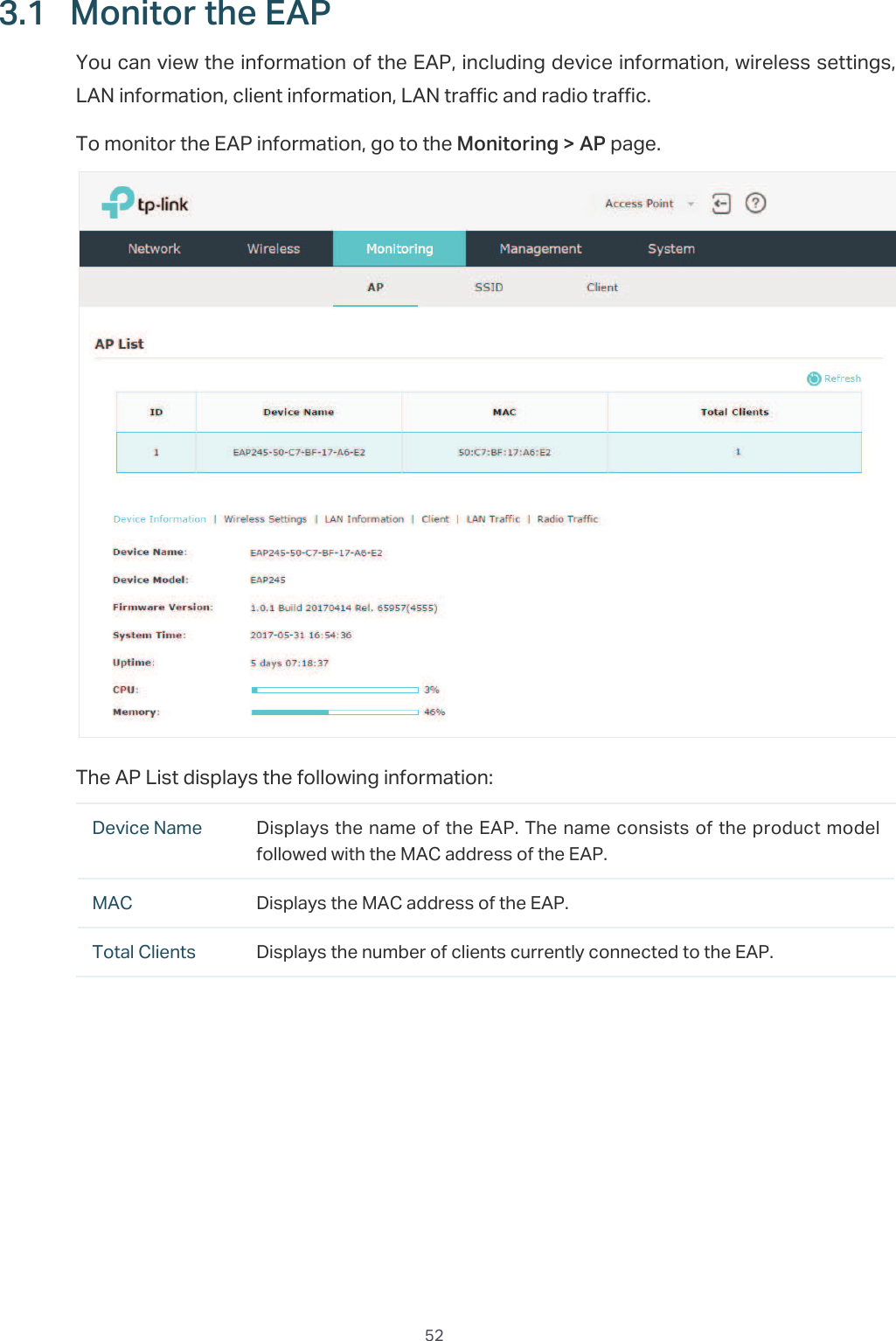
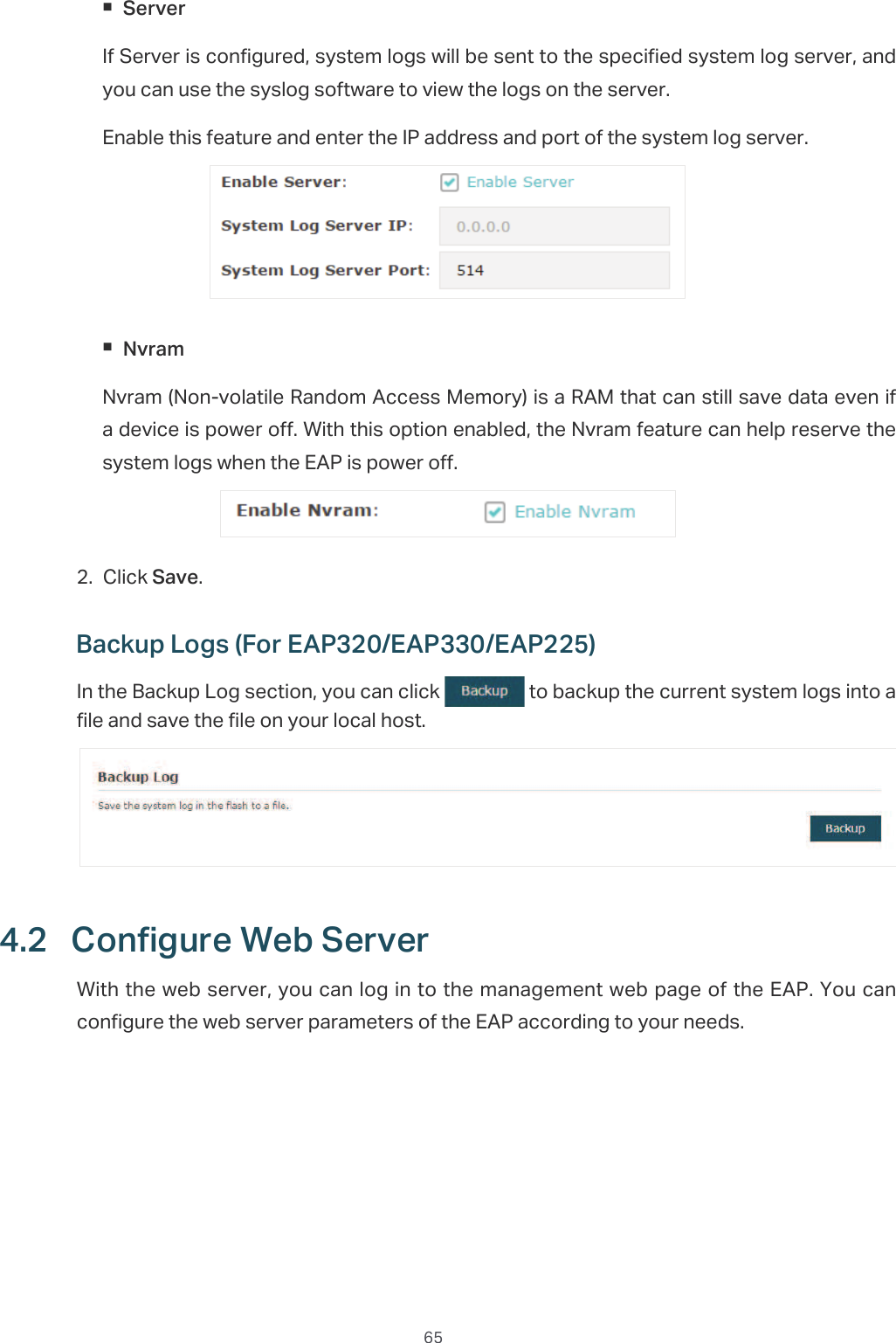
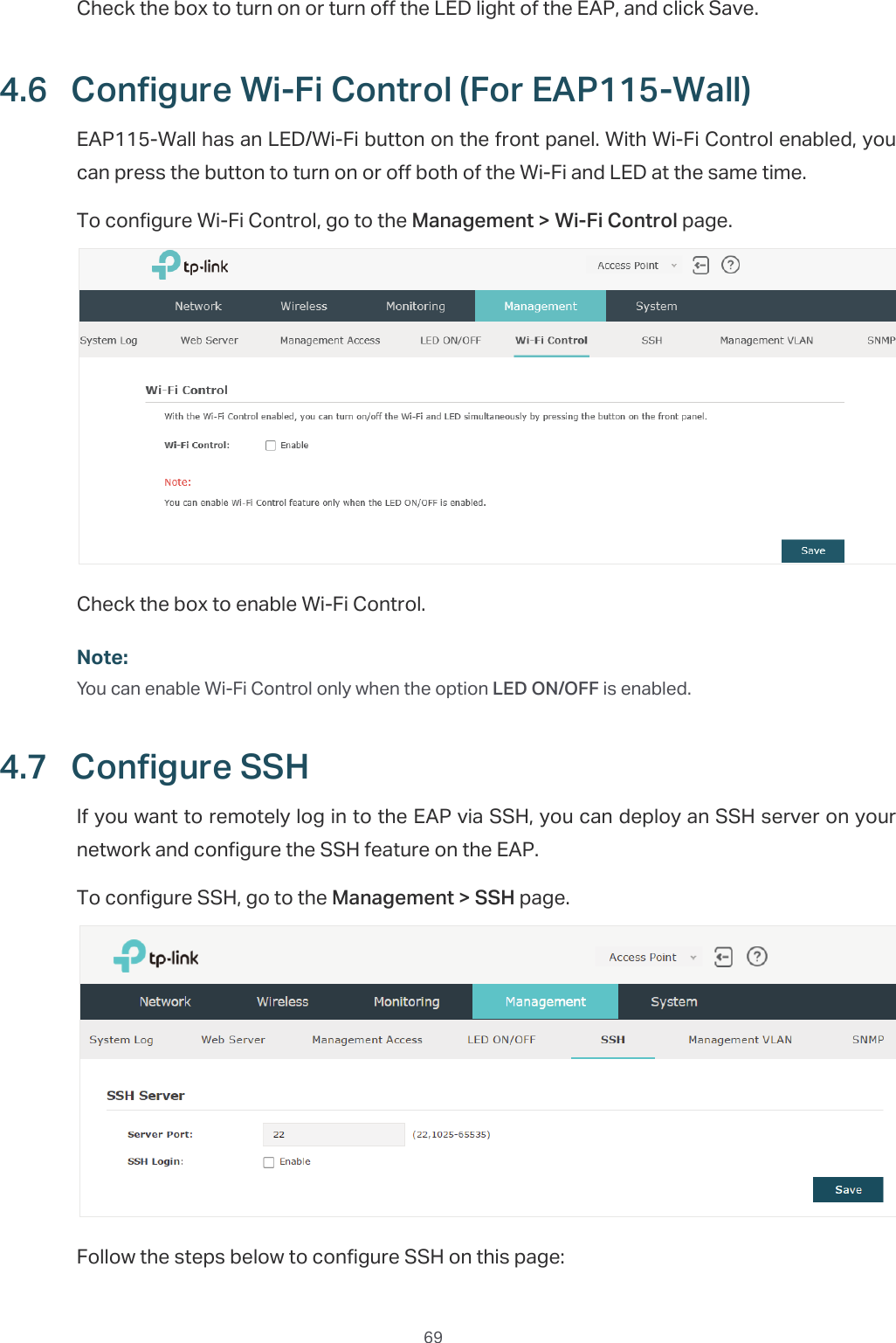
![7/RJLQYLDWKH'RPDLQ1DPHIn this method, you needn't know the IP address of the EAP, but you need to prepare a wireless client device, such as a wireless laptop. Follow the steps below to log in to the EAP wirelessly:̝Find the default SSID of the EAP. The SSID is printed on the product label at the bottom of the device, and the format is 73/,1.B*+]*+]B;;;;;;.̝Search the default SSID using your wireless client device and connect to the wireless network of the EAP.̝Launch a web browser on the client device and enter KWWSWSOLQNHDSQHW in the address bar to load the login page of the EAP. Use DGPLQ for both of the username and password to log in.̝In the pop-up window, configure a new username and a new password for your user account.](https://usermanual.wiki/TP-Link-Technologies/EAP110ODV3/User-Guide-3726803-Page-11.png)
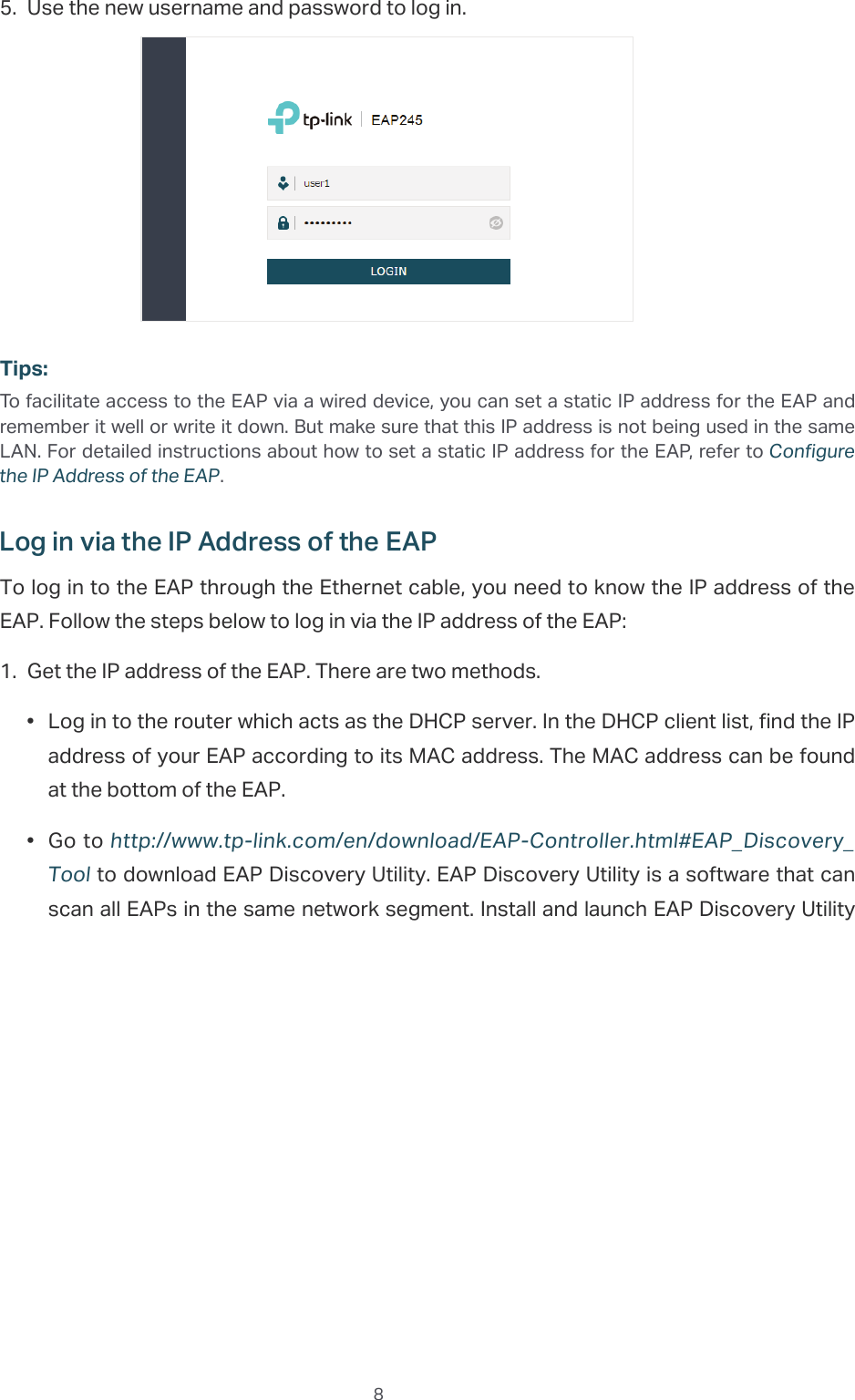
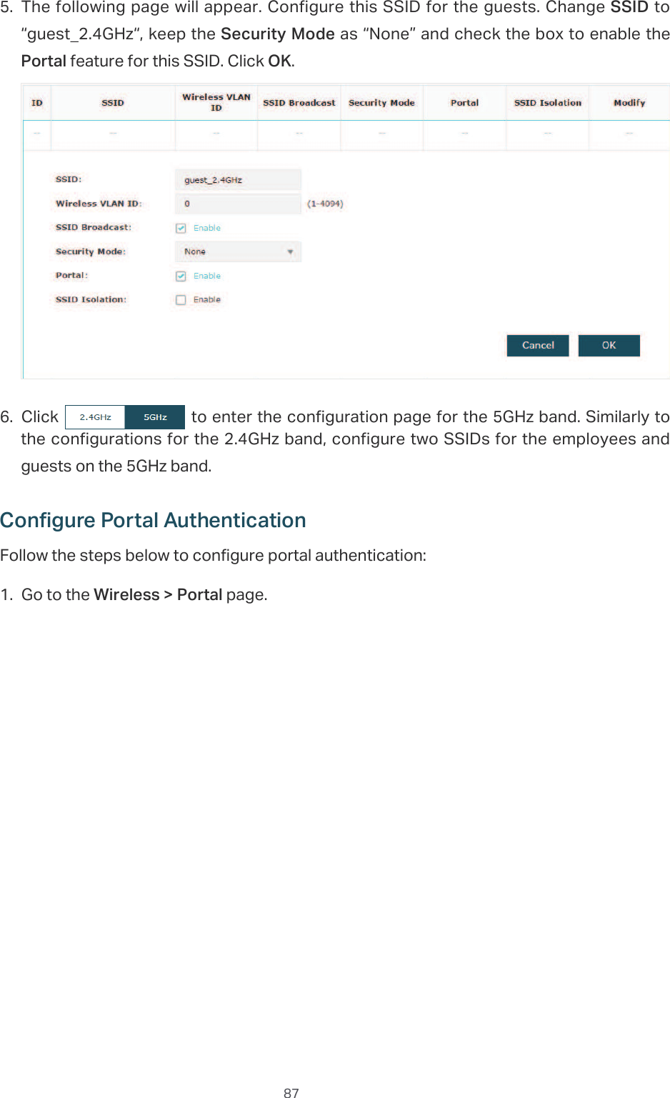
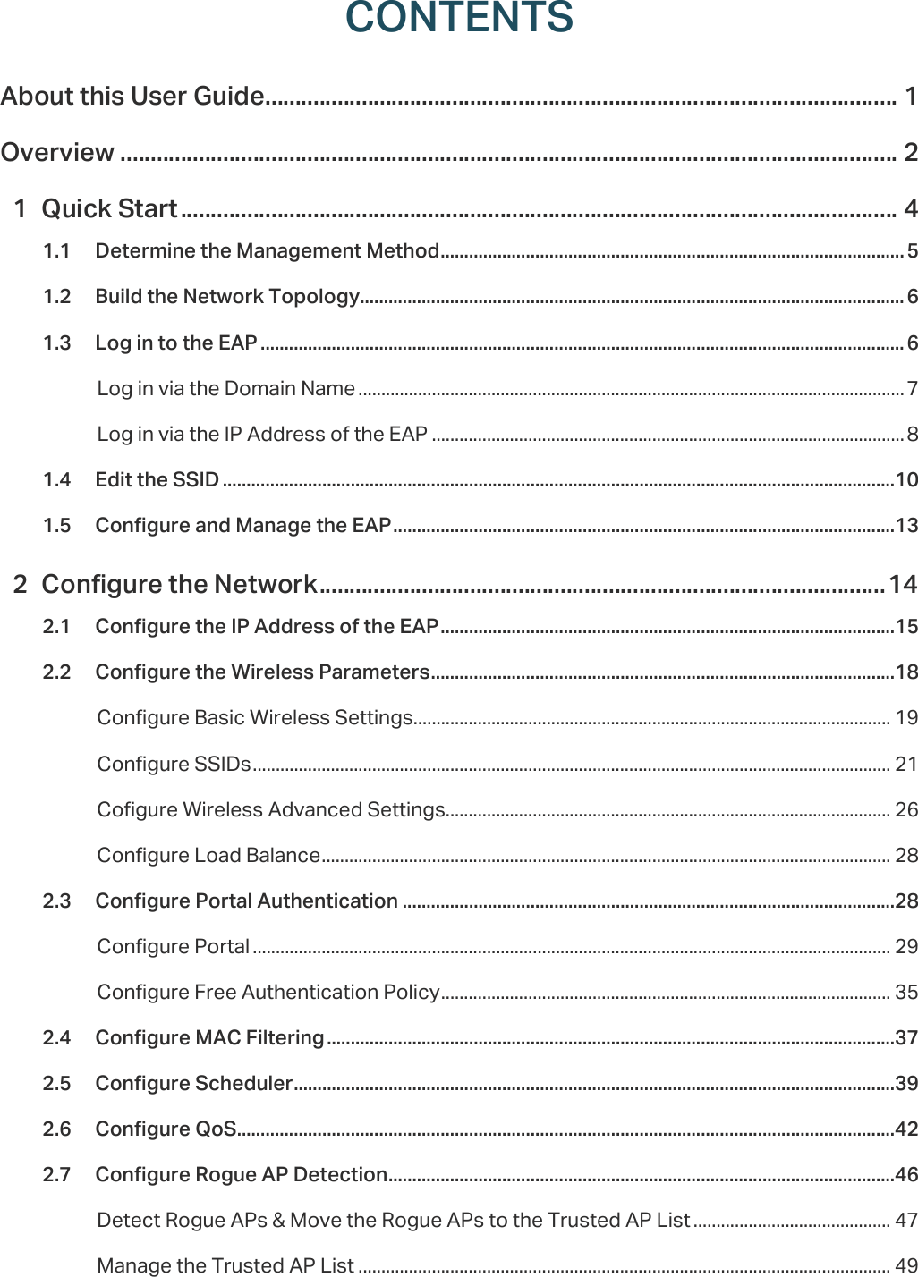
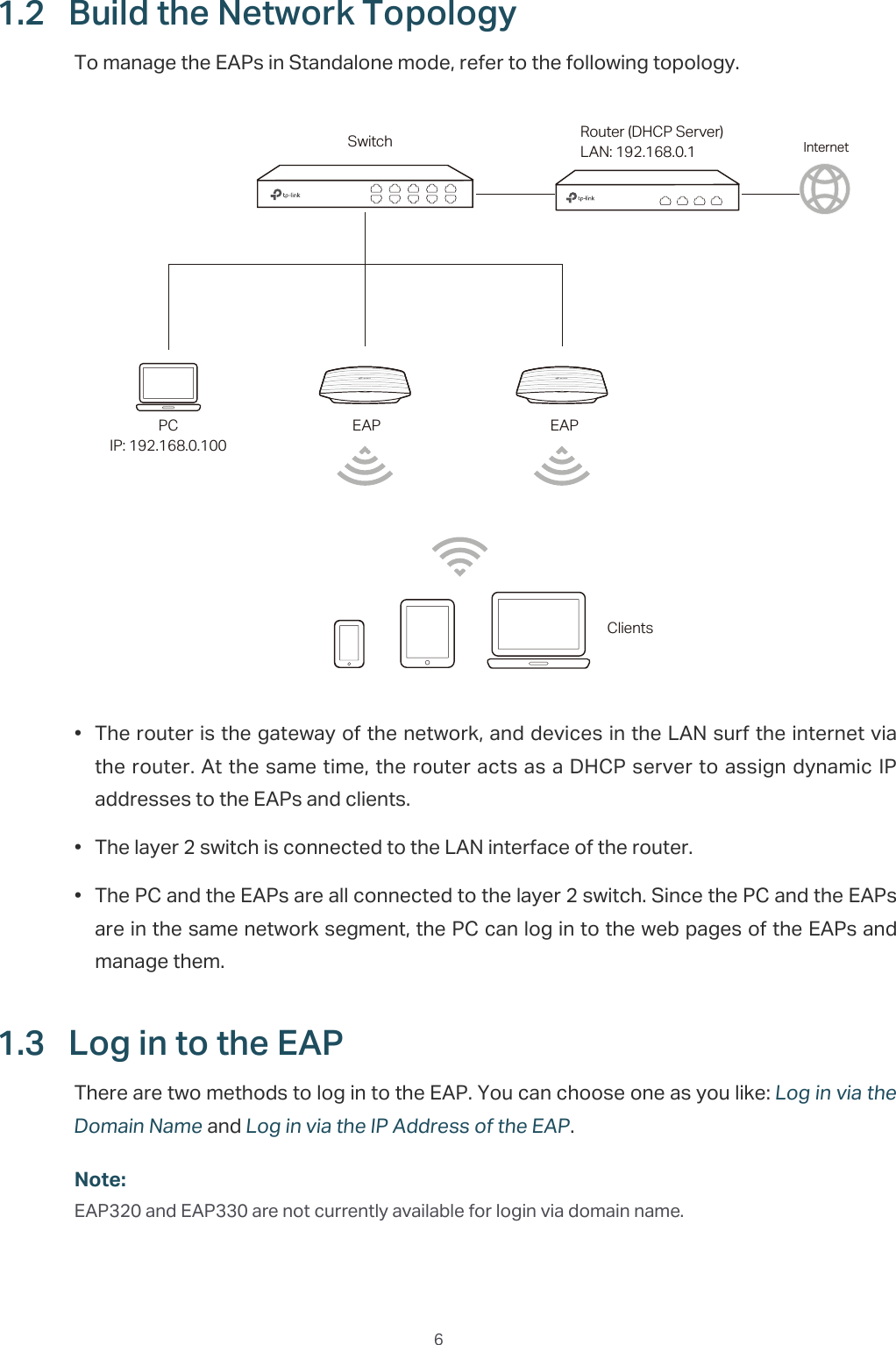
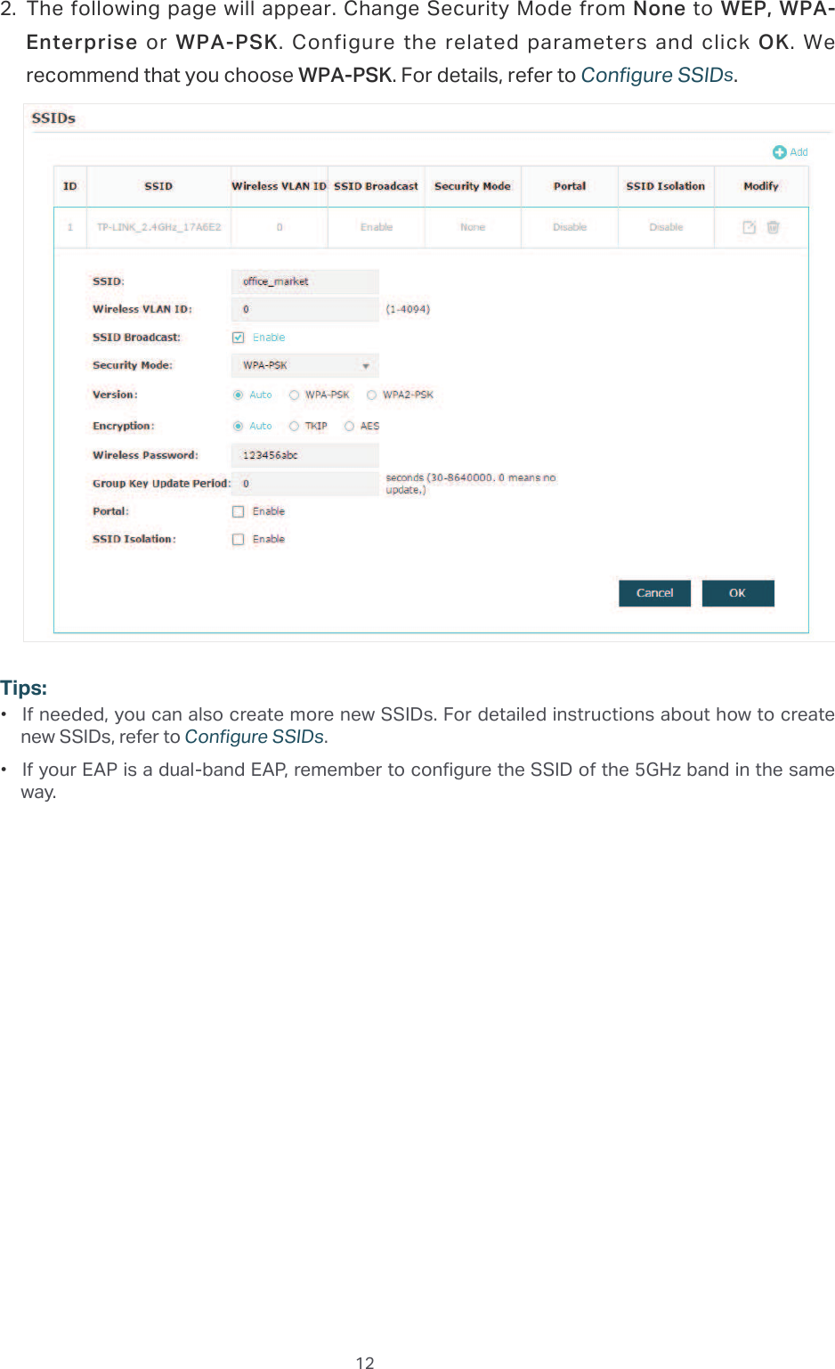
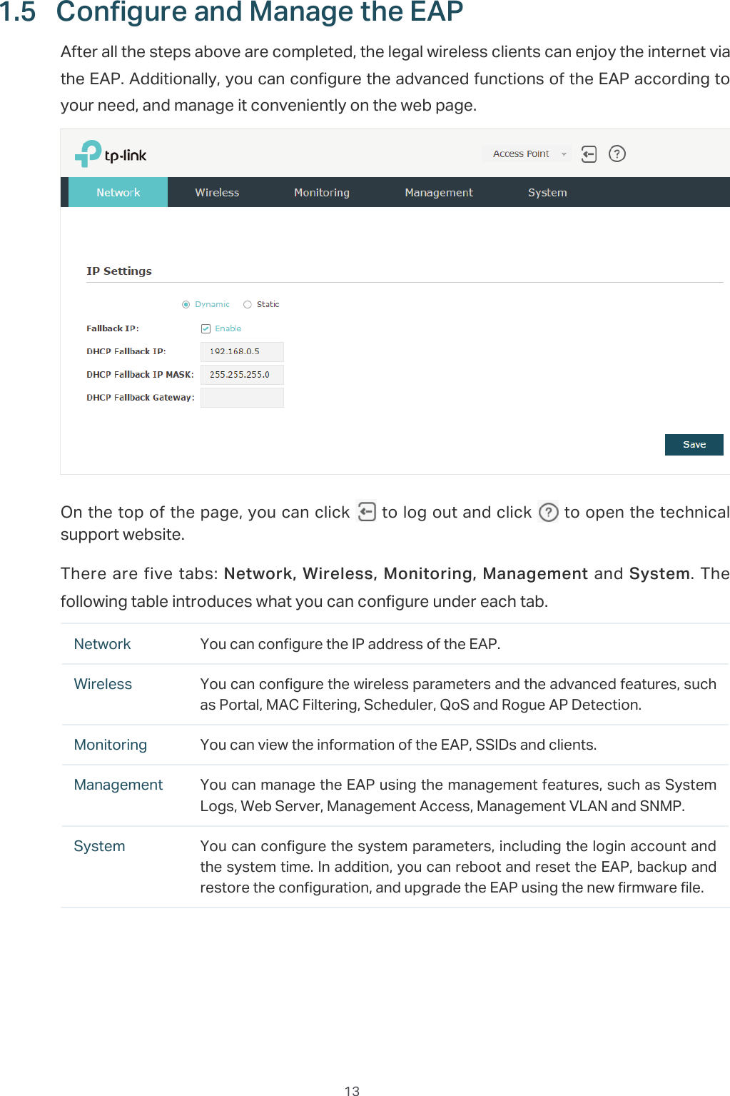
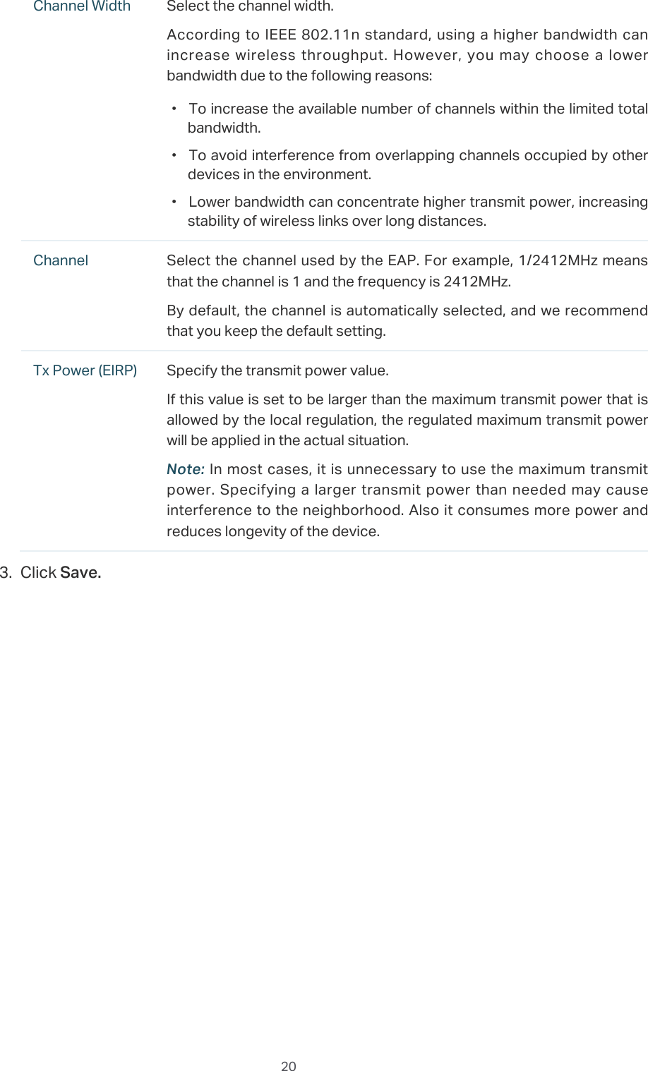
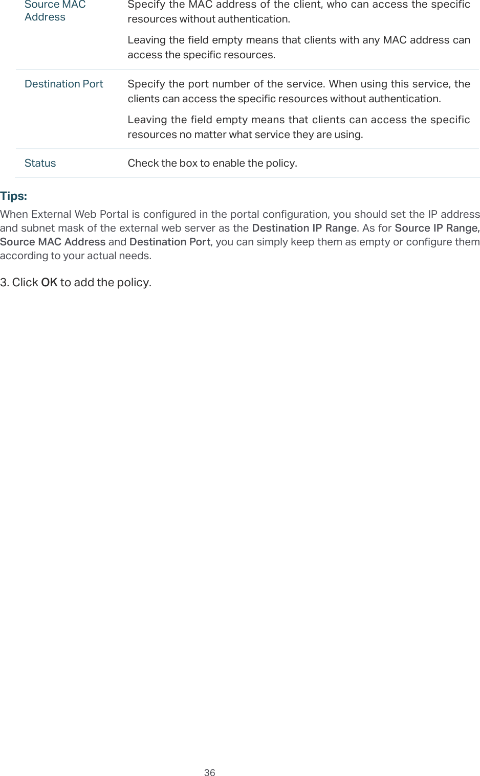
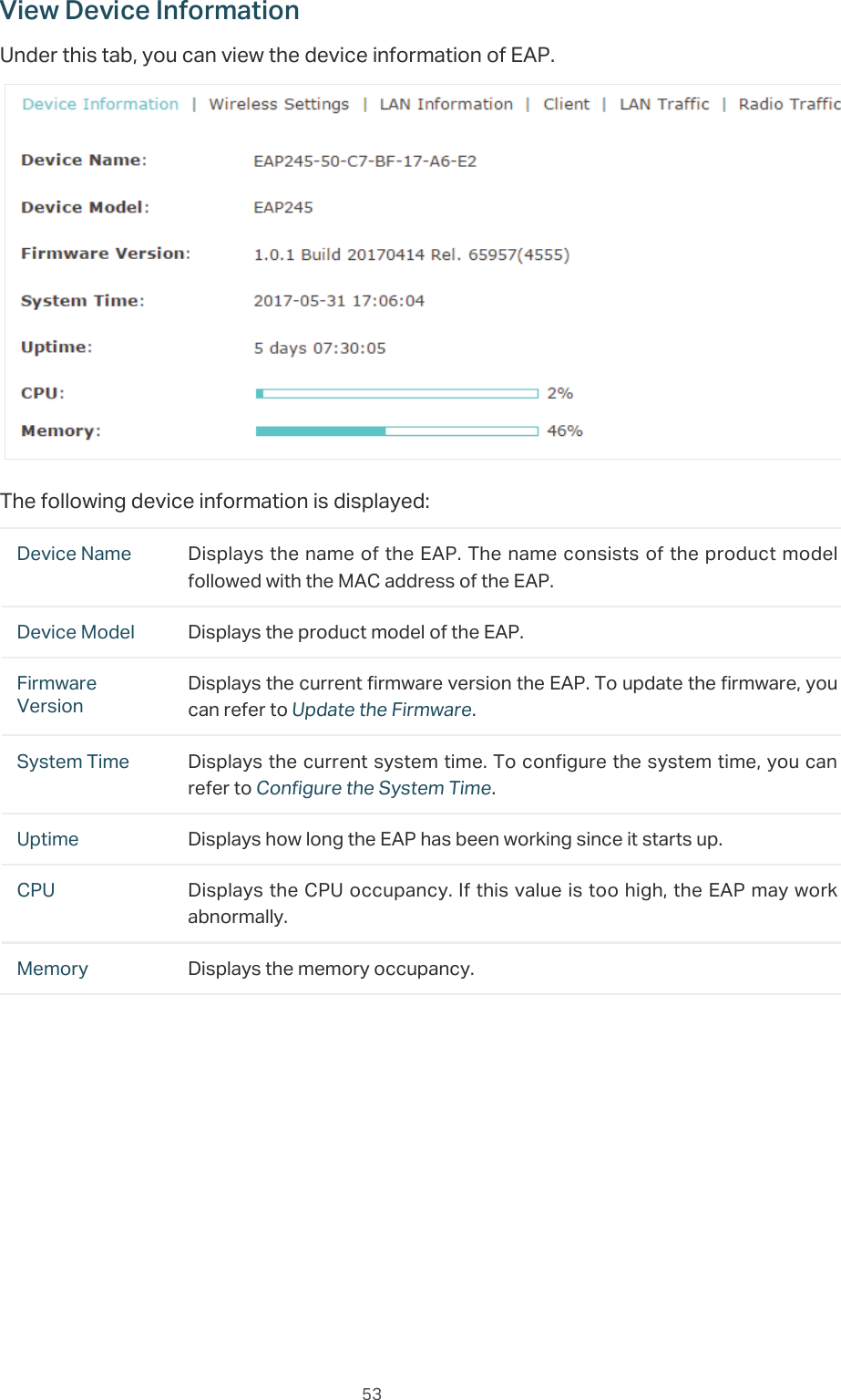
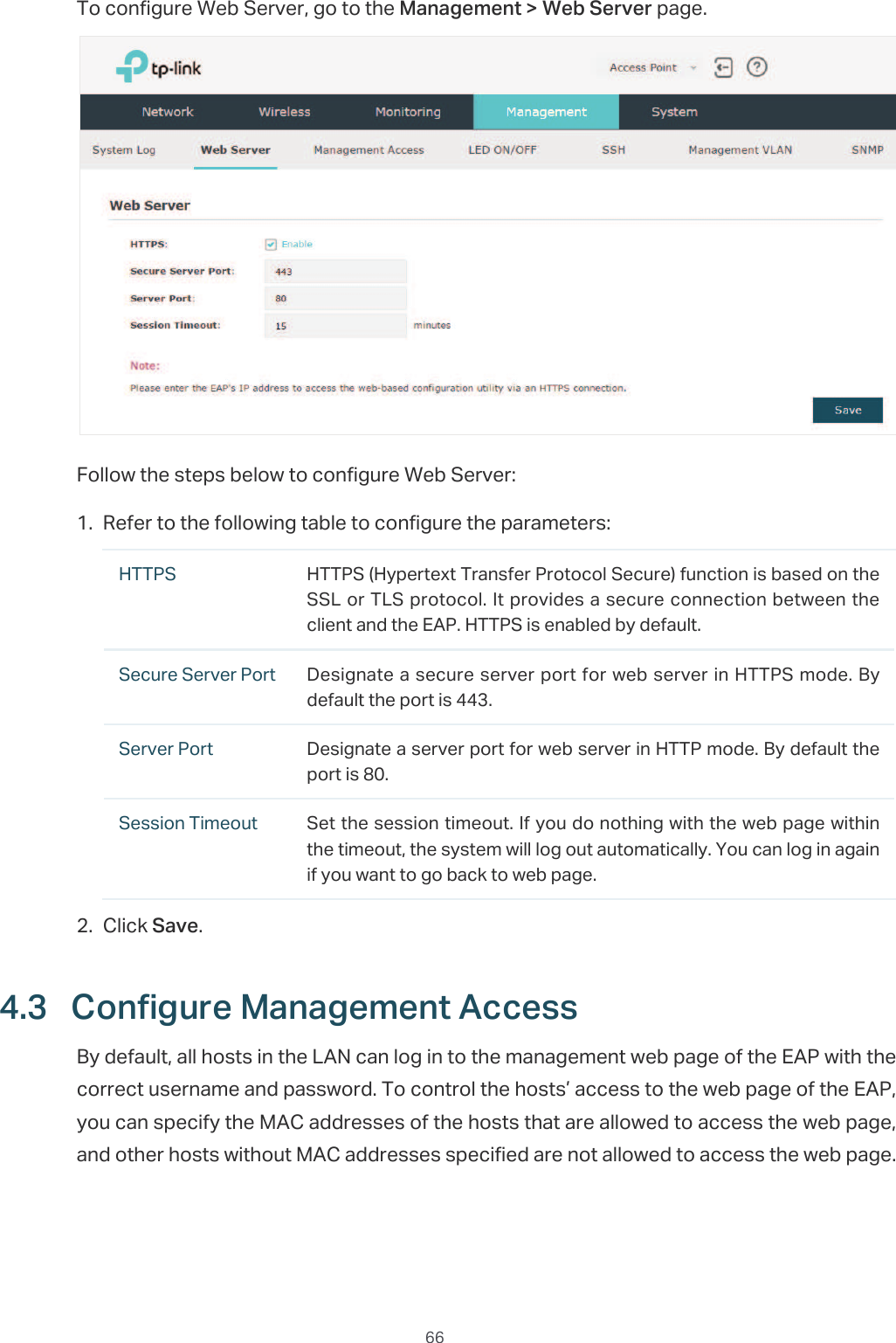
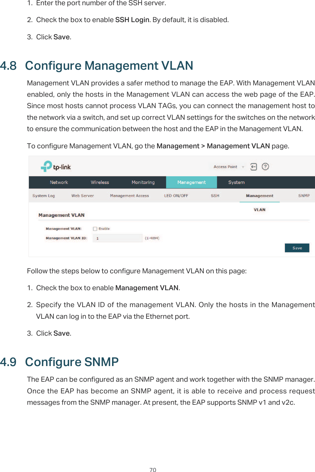
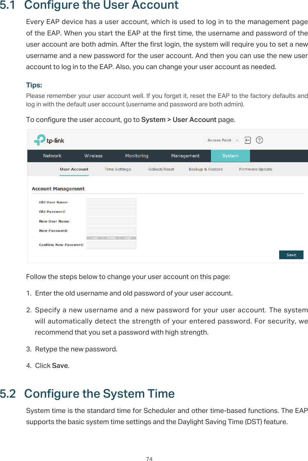
![10̝In the pop-up window, configure a new username and a new password for your user account.̝Use the new username and password to log in.Tips:To facilitate access to the EAP via a wired device, you can set a static IP address for the EAP and remember it well or write it down. But make sure that this IP address is not being used in the same LAN. For detailed instructions about how to set a static IP address for the EAP, refer to Configure the IP Address of the EAP.1.4 Edit the SSIDBy default, the dual-band EAP has two default SSIDs named 73/,1.B*+]B;;;;;; and73/,1.B*+]B;;;;;;on the 2.4GHz band and 5GHz band, and the single-band EAP has a default SSID named 73/,1.B*+]B;;;;;; on the 2.4GHz band.The default SSID has no password, so anyone can access the network without authentication. If your network is a private network, for security, we recommend that you change the SSID configuration immediately after login.Follow the steps below to edit the default SSID:](https://usermanual.wiki/TP-Link-Technologies/EAP110ODV3/User-Guide-3726803-Page-14.png)
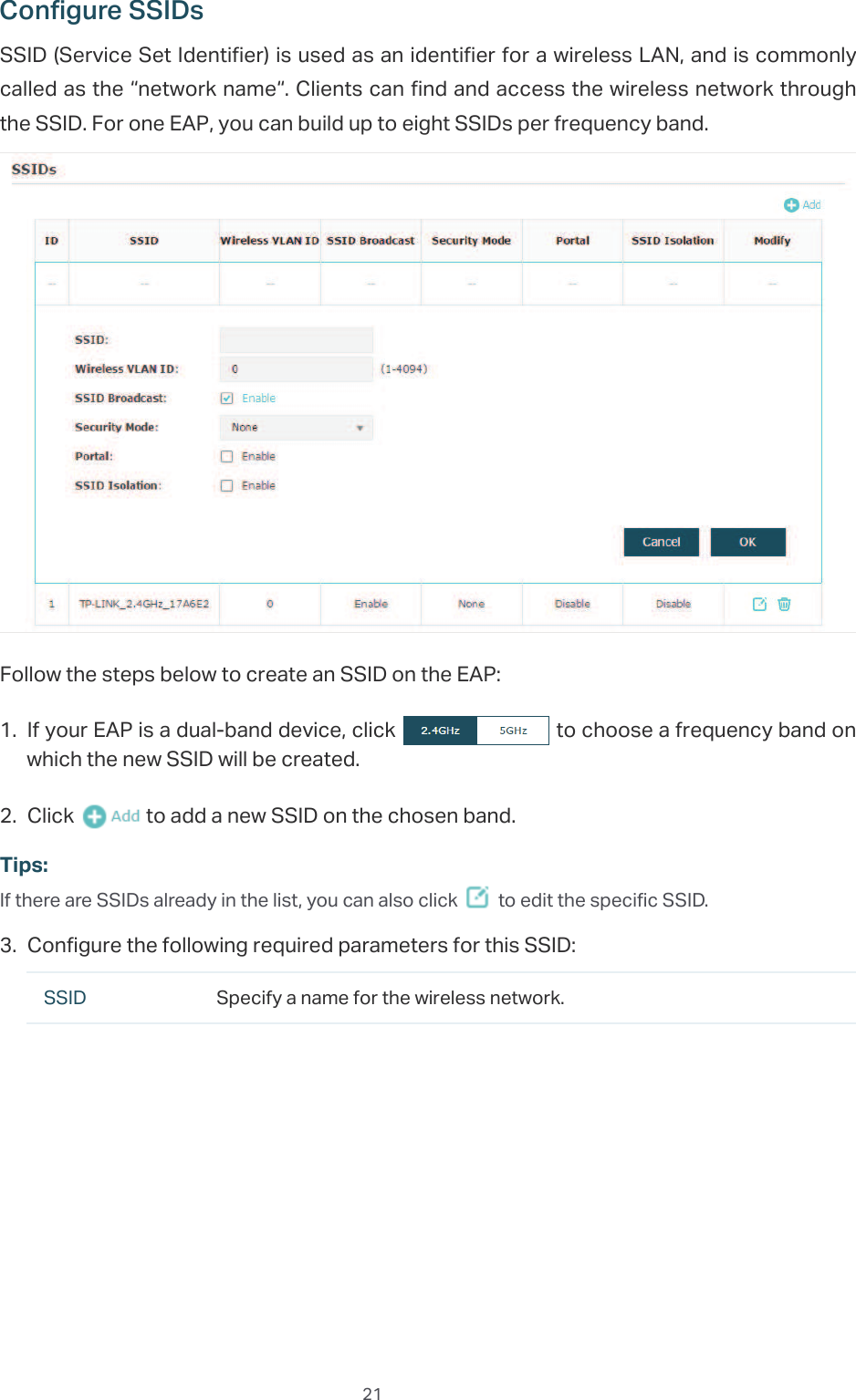
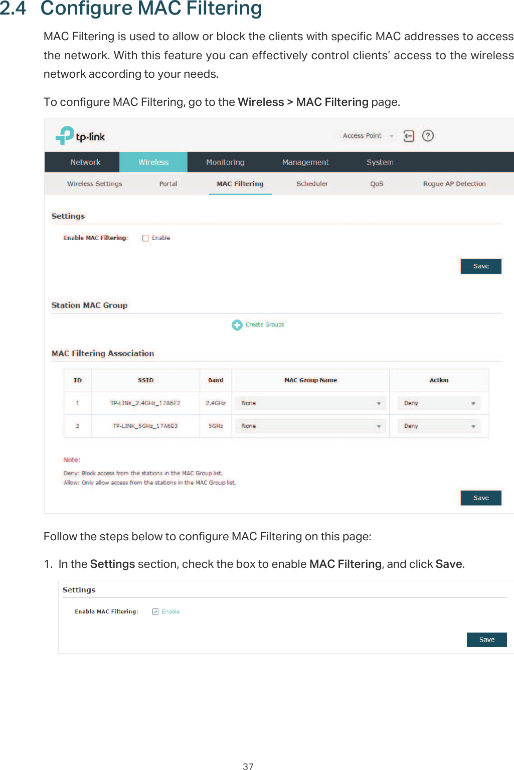
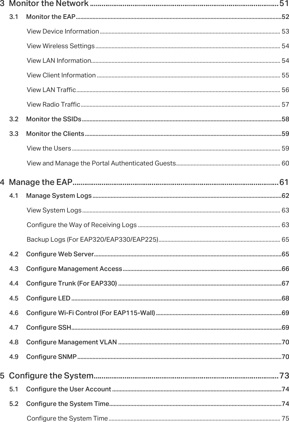
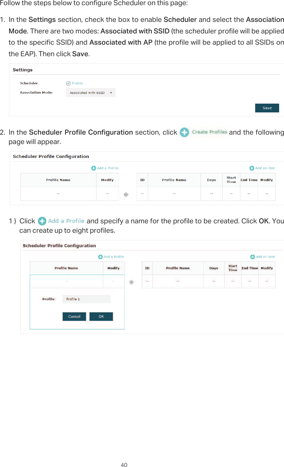
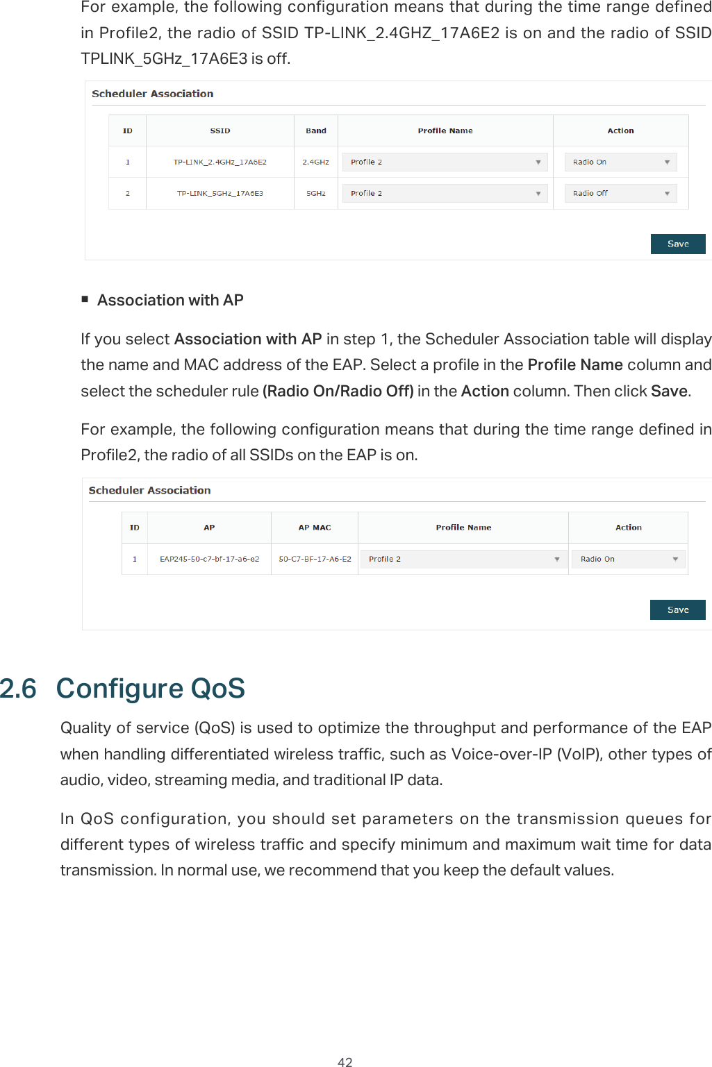
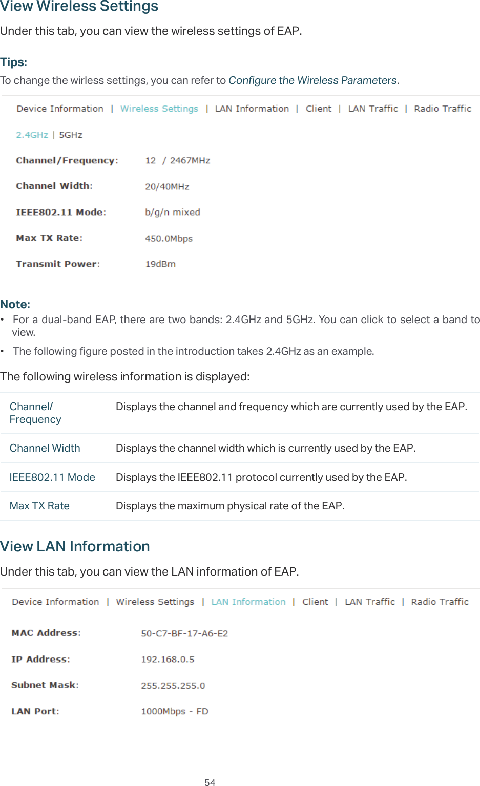
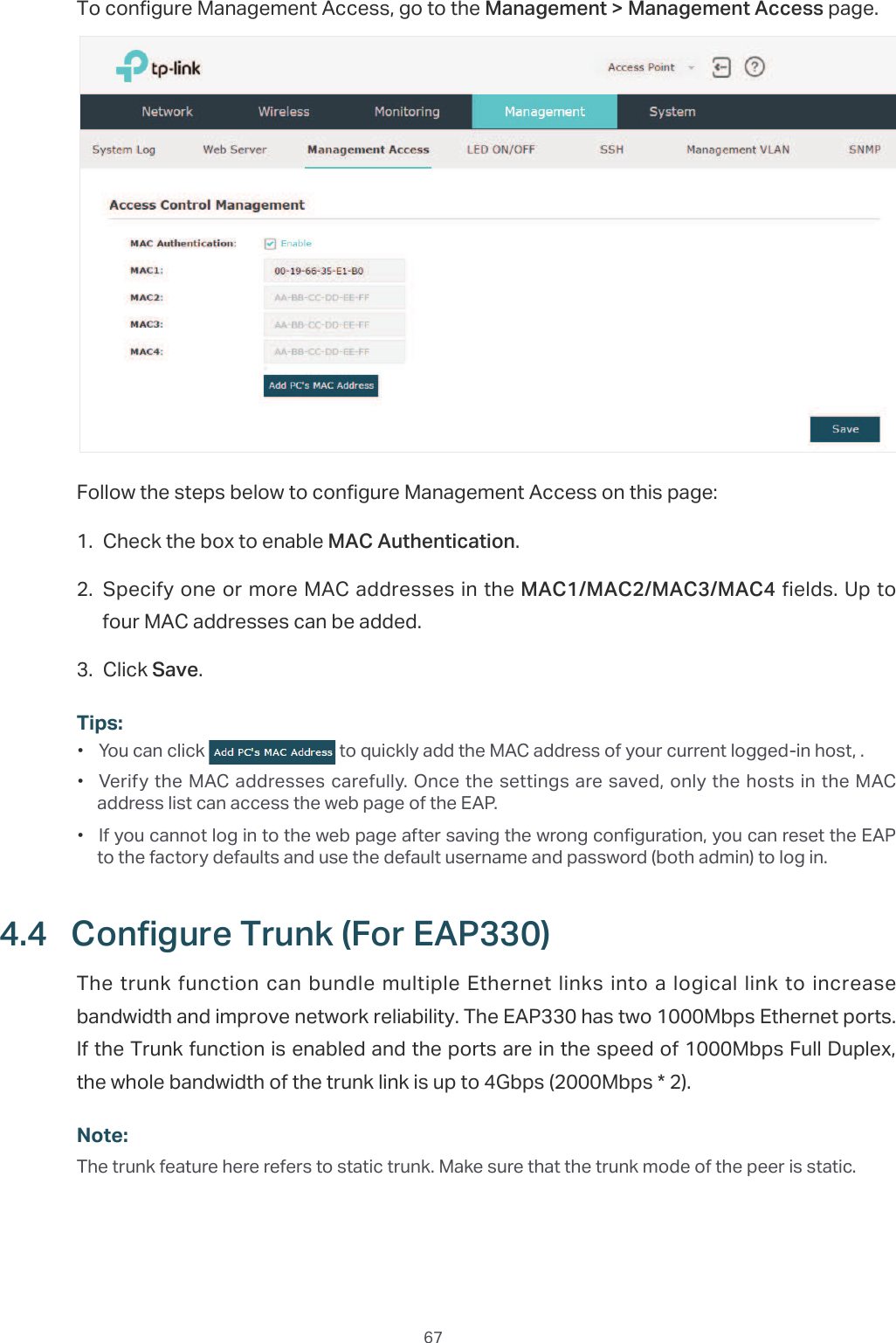
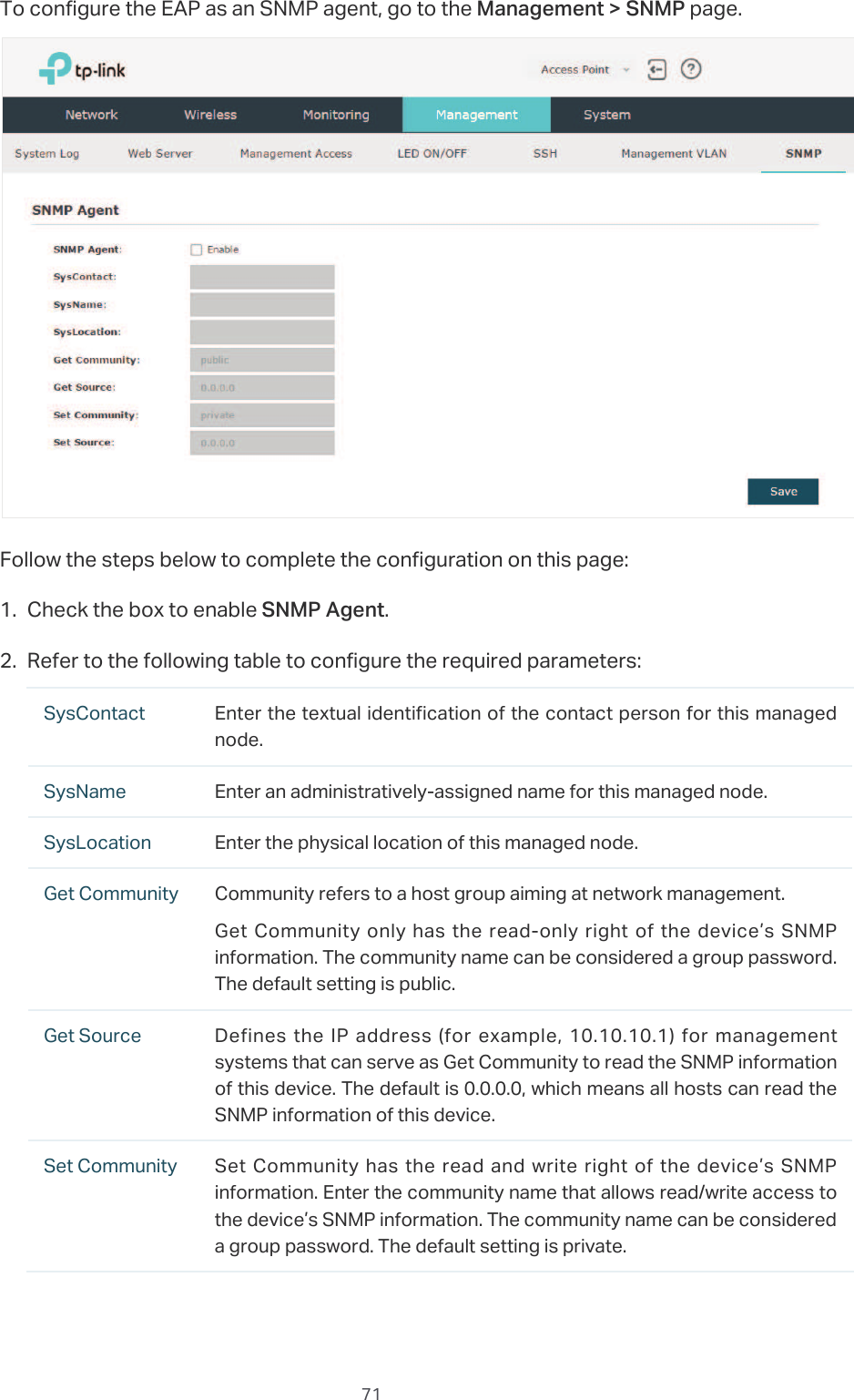
![39For example, the following configuration means that the hosts in Group 2 are denied to access the SSID73/,1.B*+]B$( on the 2.4GHz band and allowed to access the SSID 73/,1.B*+]B$(on the 5GHz band.2.5 &RQILJXUH6FKHGXOHUWith the Scheduler feature, the EAP or its wireless network can automatically turn on or off at the time you set. For example, you can schedule the radio to operate only during the office working time to reduce power consumption.To configure Scheduler, go to the:LUHOHVV!6FKHGXOHU page.](https://usermanual.wiki/TP-Link-Technologies/EAP110ODV3/User-Guide-3726803-Page-43.png)
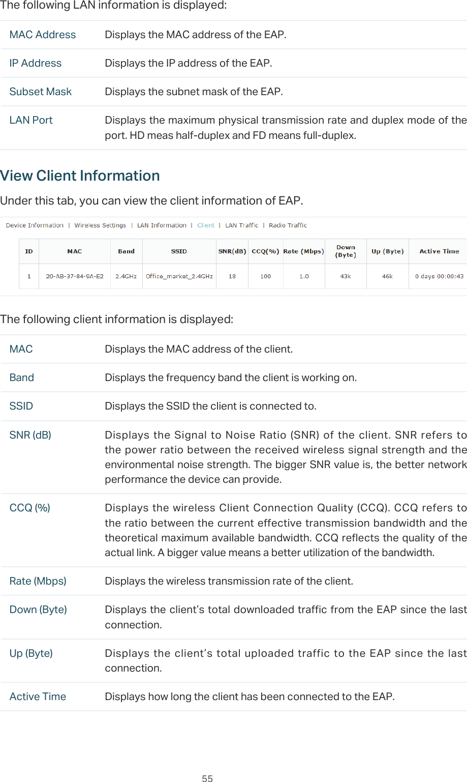
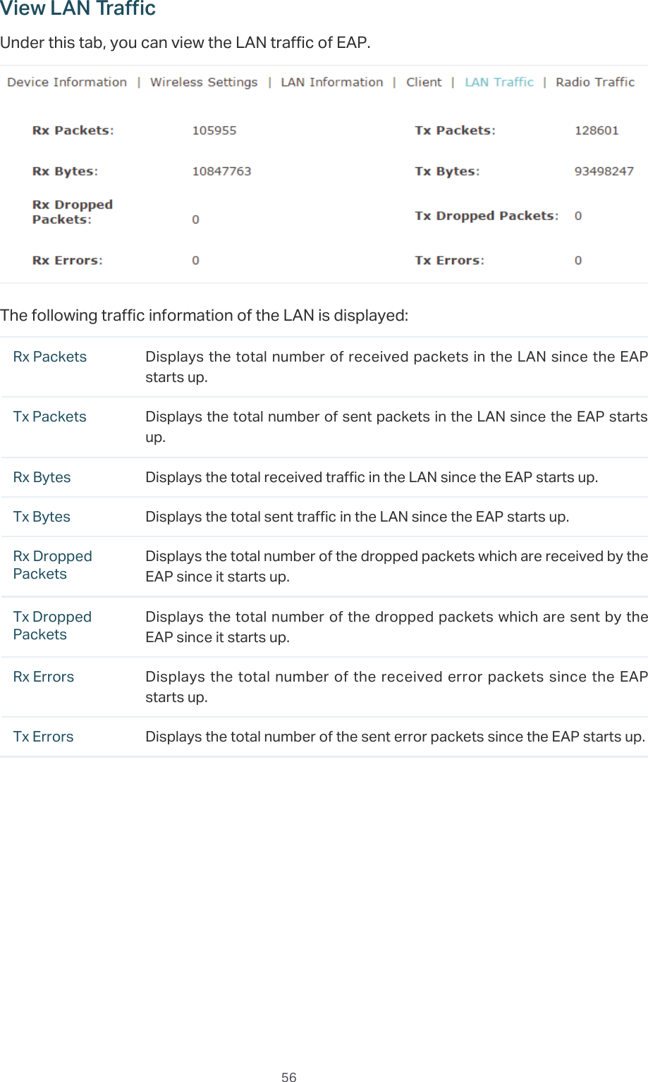
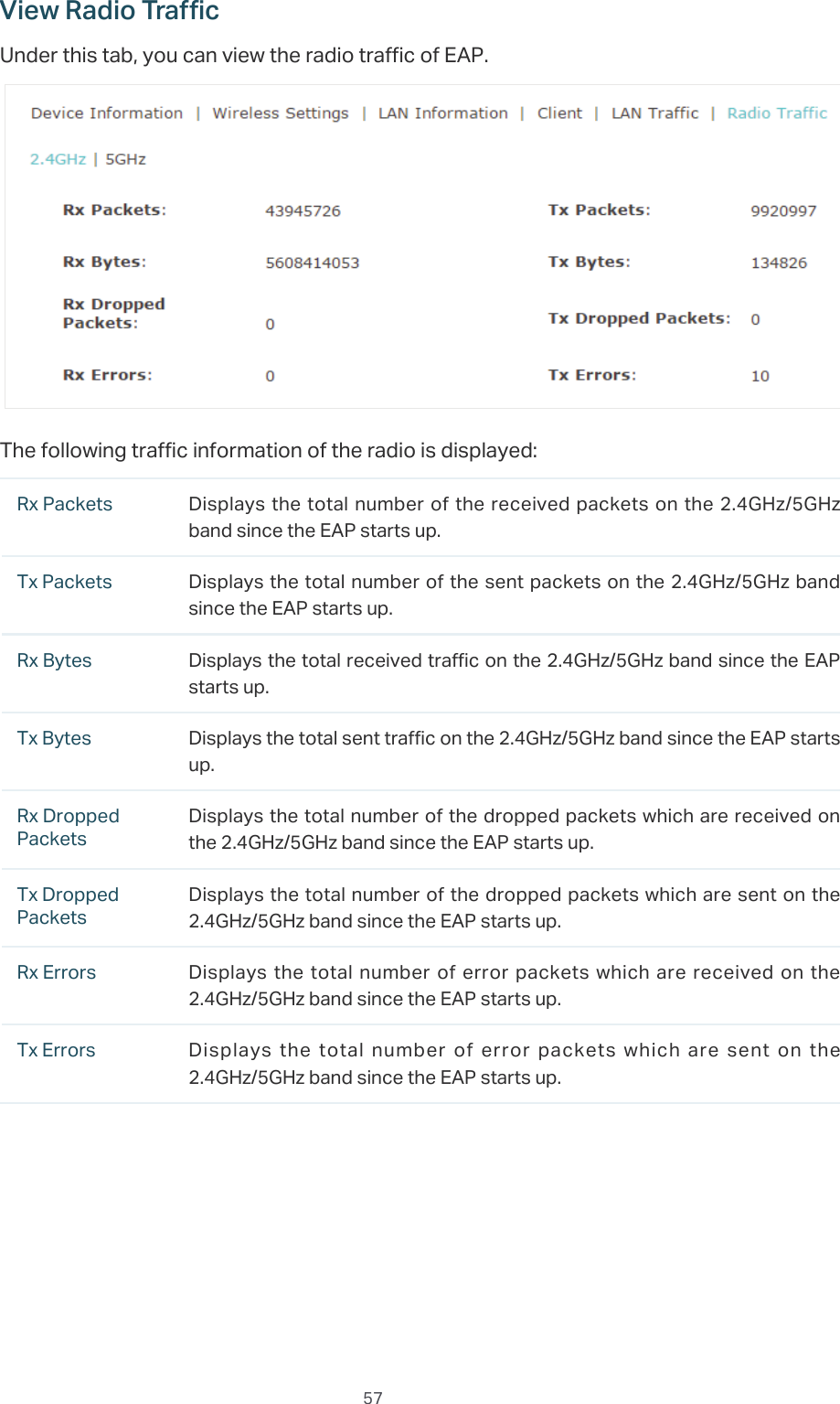
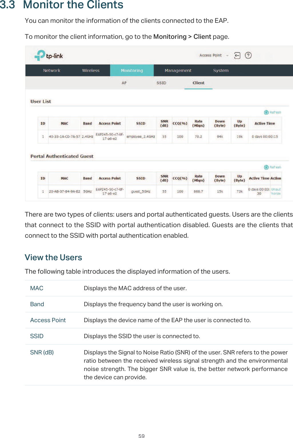
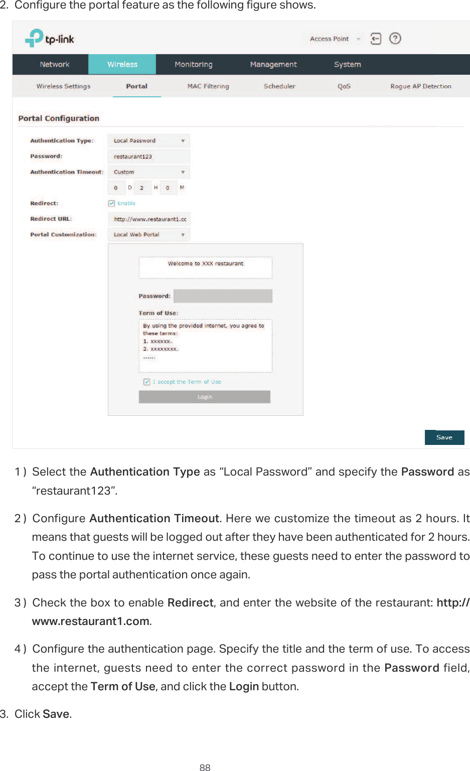
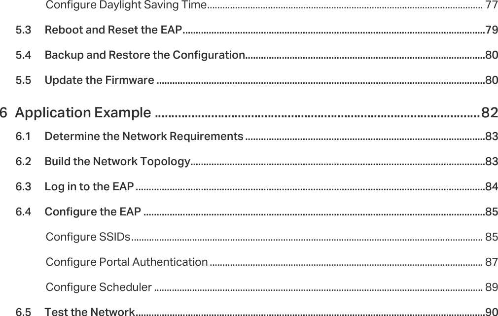
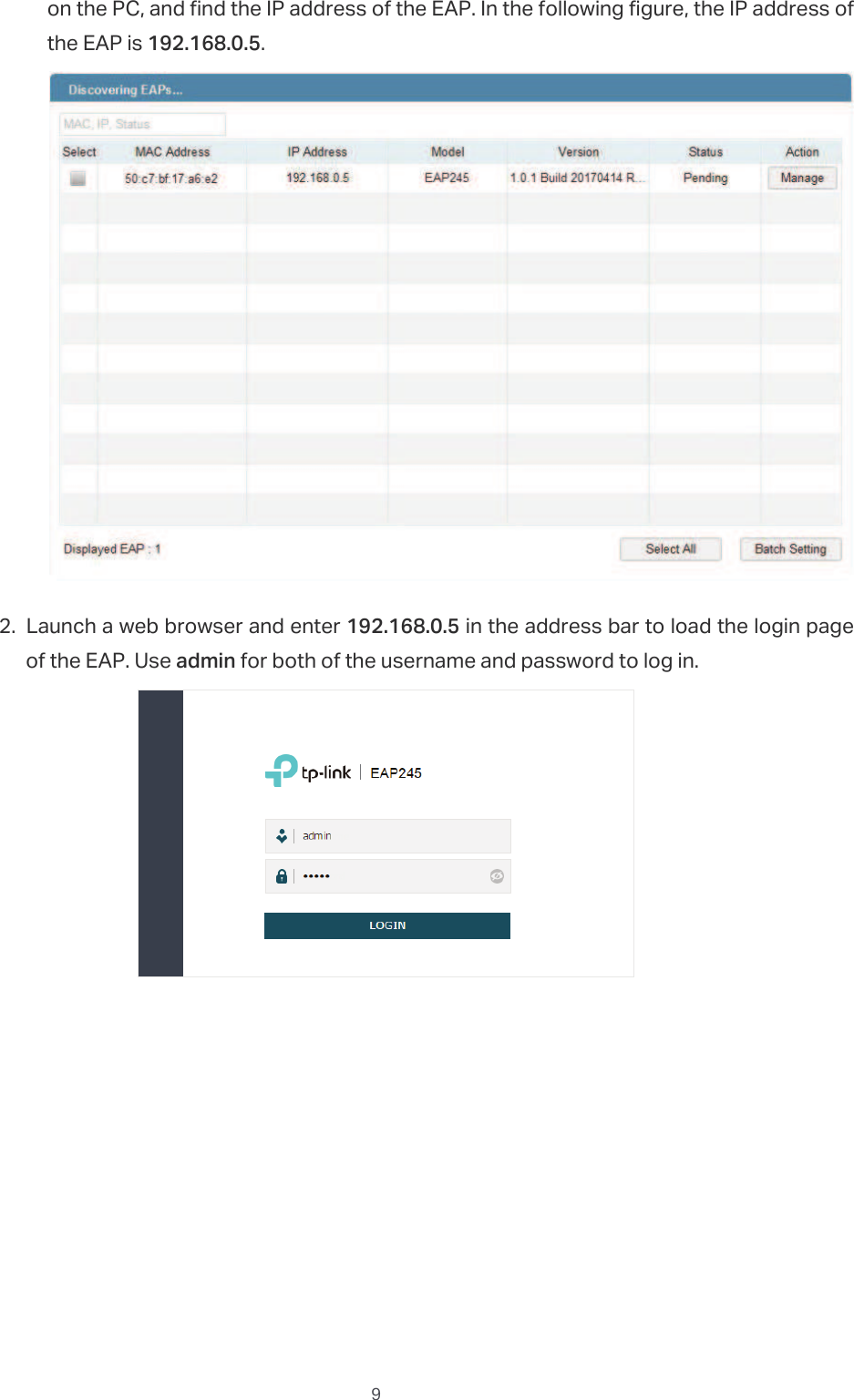
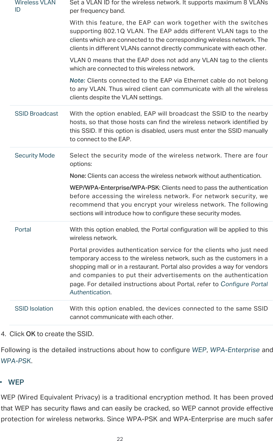
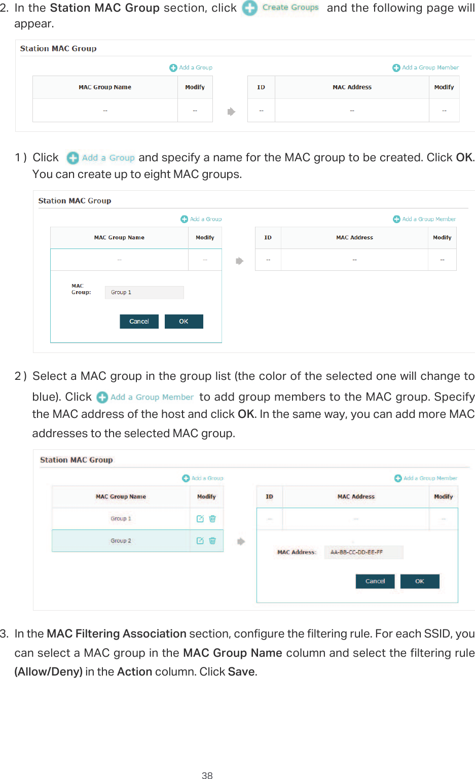
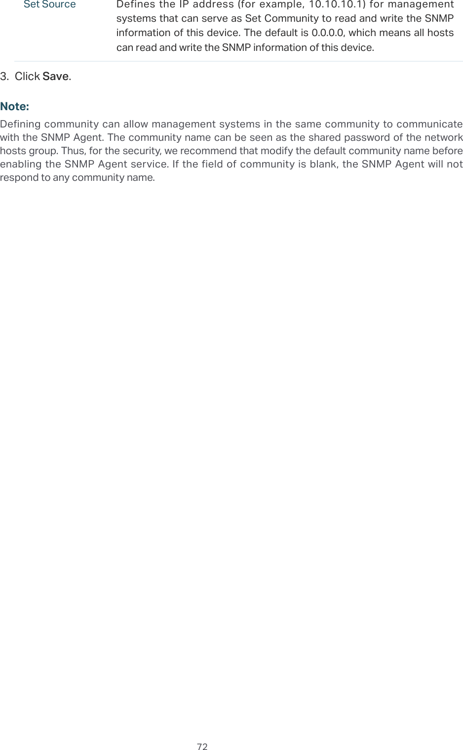
![60CCQ (%) Displays the wireless Client Connection Quality (CCQ) of the user. CCQ refers to the ratio between the current effective transmission bandwidth and the theoretical maximum available bandwidth. CCQ reflects the quality of the actual link. A bigger value means a better utilization of the bandwidth.Rate (Mbps) Displays the wireless transmission rate of the user.Down (Byte) Displays the user’s total downloaded traffic from the EAP since the last connection.Up (Byte) Displays the user’s total uploaded traffic to the EAP since the last connection.Active Time Displays how long the user has been connected to the EAP.9LHZDQG0DQDJHWKH3RUWDO$XWKHQWLFDWHG*XHVWVThe following table introduces the displayed information of the portal authentication guests.MAC Displays the MAC address of the user.Band Displays the frequency band the user is working on.Access Point Displays the device name of the EAP the user is connected to.SSID Displays the SSID the user is connected to.SNR (dB) Displays the Signal to Noise Ratio (SNR) of the user. SNR refers to the power ratio between the received wireless signal strength and the environmental noise strength. The bigger SNR value is, the better network performance the device can provide.CCQ (%) Displays the wireless Client Connection Quality (CCQ) of the user. CCQ refers to the ratio between the current effective transmission bandwidth and the theoretical maximum available bandwidth. CCQ reflects the quality of the actual link. A bigger value means a better utilization of the bandwidth.Rate (Mbps) Displays the wireless transmission rate of the user.Down (Byte) Displays the user’s total downloaded traffic from the EAP since the last connection.Up (Byte) Displays the user’s total uploaded traffic to the EAP since the last connection.Active Time Displays how long the user has been connected to the EAP.In the $FWLRQ column, you can click 8QDXWKRUL]Hto delete the authentication information of the guest. To access the internet, the guest needs to log in again.](https://usermanual.wiki/TP-Link-Technologies/EAP110ODV3/User-Guide-3726803-Page-64.png)
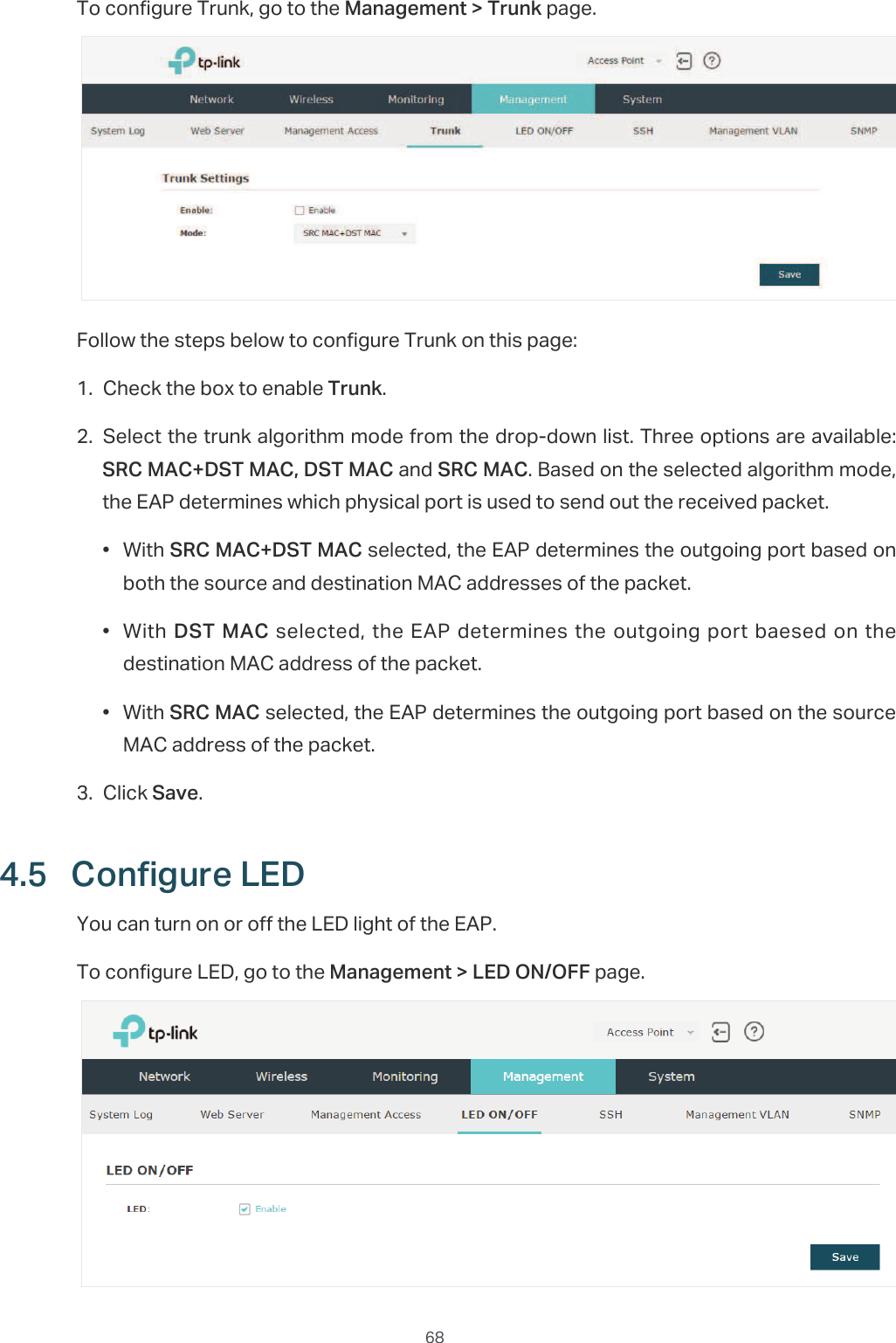
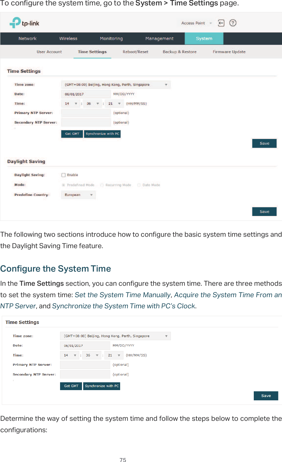

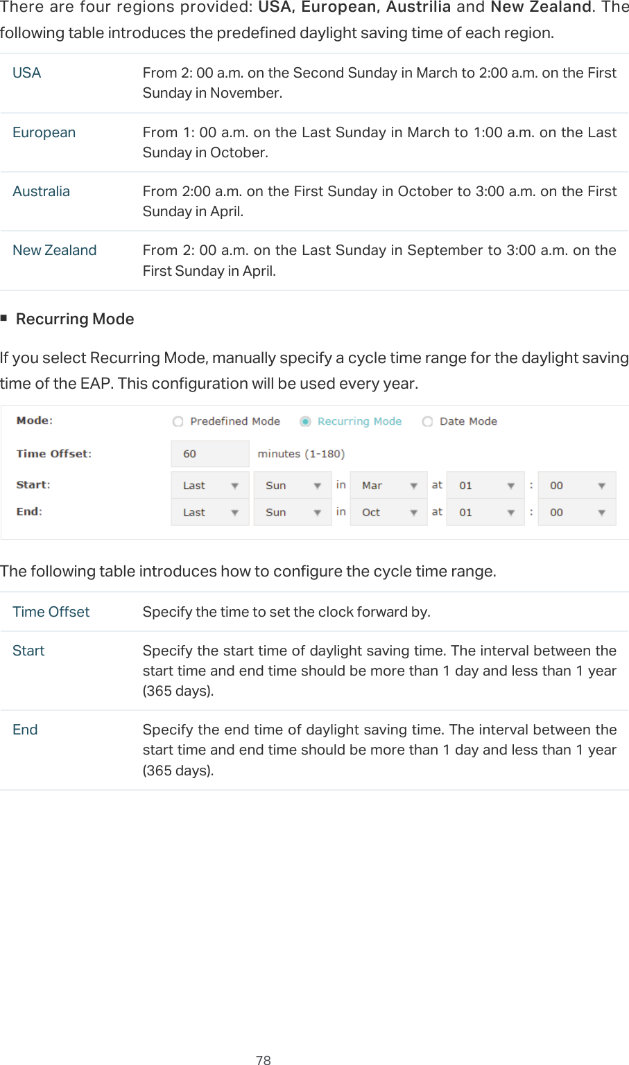
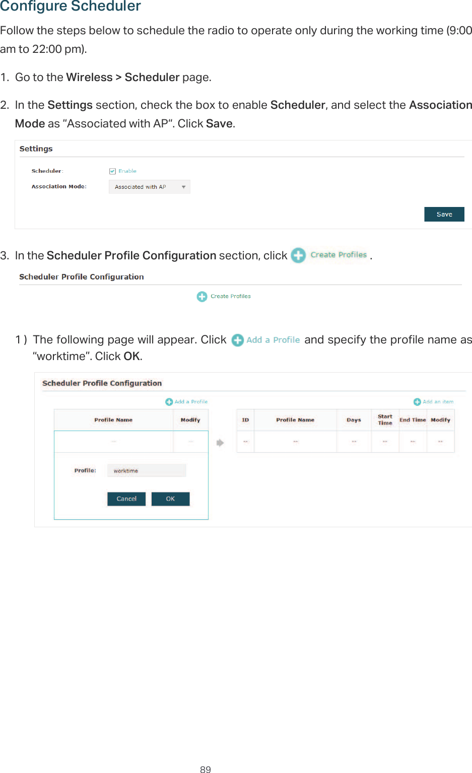
![77̝Click 6DYH.̝g6\QFKURQL]HWKH6\VWHP7LPHZLWK3&oV&ORFNTo synchronize the system time with the clock of your currently logged-in host, follow the steps below:̝Click the button and the synchronized system time will be displayed in the 'DWH and Time fields.̝Click6DYH.Note:The system time synchronized with PC’s clock will be lost after the EAP is rebooted. &RQILJXUH'D\OLJKW6DYLQJ7LPHDaylight saving time is the practice of advancing clocks during summer months so that evening daylight lasts longer, while sacrificing normal sunrise times. The EAP provides daylight saving time configuration.Follow the steps below to configure daylight saving time:̝Check the box to enable 'D\OLJKW6DYLQJ̝Select the mode of daylight saving time. Three modes are available: 3UHGHILQHG0RGH5HFXUULQJ0RGHand'DWH0RGH.̝Configure the related parameters of the selected mode.3UHGHILQHG0RGHIf you select Predefined Mode, choose your region from the drop-down list and the EAP will use the predefined daylight saving time of the selected region.](https://usermanual.wiki/TP-Link-Technologies/EAP110ODV3/User-Guide-3726803-Page-81.png)