TP Link Technologies EAP110ODV3 300Mbps Wireless N Outdoor Access Point User Manual Rev 1
TP-Link Technologies Co., Ltd. 300Mbps Wireless N Outdoor Access Point Rev 1
user manual_Rev

User Guide
For TP-Link Omada Access Points
EAP110 / EAP115 / EAP225 / EAP245 / EAP320 / EAP330 / EAP115-Wall
EAP110-Outdoor / EAP225-Outdoor
1910012254 REV 2.0.2
September 2017
CONTENTS
About this User Guide ......................................................................................................... 1
Overview ................................................................................................................................. 2
̝̝4XLFN6WDUW ....................................................................................................................... 4
'HWHUPLQHWKH0DQDJHPHQW0HWKRG .................................................................................................. 5
%XLOGWKH1HWZRUN7RSRORJ\ ................................................................................................................... 6
/RJLQWRWKH($3 ........................................................................................................................................ 6
Log in via the Domain Name .......................................................................................................................7
Log in via the IP Address of the EAP .......................................................................................................8
1.4 Edit the SSID ..............................................................................................................................................10
&RQILJXUHDQG0DQDJHWKH($3 ..........................................................................................................13
̝̝&RQILJXUHWKH1HWZRUN ..............................................................................................14
&RQILJXUHWKH,3$GGUHVVRIWKH($3 ................................................................................................15
&RQILJXUHWKH:LUHOHVV3DUDPHWHUV ..................................................................................................18
Configure Basic Wireless Settings ........................................................................................................ 19
Configure SSIDs ........................................................................................................................................... 21
Cofigure Wireless Advanced Settings................................................................................................. 26
Configure Load Balance ............................................................................................................................ 28
&RQILJXUH3RUWDO$XWKHQWLFDWLRQ ........................................................................................................28
Configure Portal ........................................................................................................................................... 29
Configure Free Authentication Policy .................................................................................................. 35
&RQILJXUH0$&)LOWHULQJ ........................................................................................................................37
&RQILJXUH6FKHGXOHU ...............................................................................................................................39
&RQILJXUH4R6 ...........................................................................................................................................42
&RQILJXUH5RJXH$3'HWHFWLRQ ...........................................................................................................46
Detect Rogue APs & Move the Rogue APs to the Trusted AP List ........................................... 47
Manage the Trusted AP List .................................................................................................................... 49
̝̝0RQLWRUWKH1HWZRUN .................................................................................................. 51
0RQLWRUWKH($3 ........................................................................................................................................52
View Device Information ........................................................................................................................... 53
View Wireless Settings .............................................................................................................................. 54
View LAN Information................................................................................................................................. 54
View Client Information ............................................................................................................................. 55
View LAN Traffic ........................................................................................................................................... 56
View Radio Traffic ........................................................................................................................................ 57
3.2 Monitor the SSIDs ....................................................................................................................................58
3.3 Monitor the Clients ..................................................................................................................................59
View the Users .............................................................................................................................................. 59
View and Manage the Portal Authenticated Guests ....................................................................... 60
̝̝0DQDJHWKH($3 ...........................................................................................................61
0DQDJH6\VWHP/RJV .............................................................................................................................62
View System Logs ....................................................................................................................................... 63
Configure the Way of Receiving Logs ................................................................................................. 63
Backup Logs (For EAP320/EAP330/EAP225) ................................................................................... 65
&RQILJXUH:HE6HUYHU............................................................................................................................65
&RQILJXUH0DQDJHPHQW$FFHVV .........................................................................................................66
&RQILJXUH7UXQN)RU($3 ............................................................................................................67
&RQILJXUH/(' ...........................................................................................................................................68
&RQILJXUH:L)L&RQWURO)RU($3:DOO ...................................................................................69
&RQILJXUH66+ ...........................................................................................................................................69
&RQILJXUH0DQDJHPHQW9/$1 ............................................................................................................70
&RQILJXUH6103 .......................................................................................................................................70
̝̝&RQILJXUHWKH6\VWHP ................................................................................................ 73
&RQILJXUHWKH8VHU$FFRXQW ................................................................................................................74
&RQILJXUHWKH6\VWHP7LPH..................................................................................................................74
Configure the System Time ..................................................................................................................... 75
Configure Daylight Saving Time ............................................................................................................. 77
5HERRWDQG5HVHWWKH($3 ....................................................................................................................79
%DFNXSDQG5HVWRUHWKH&RQILJXUDWLRQ............................................................................................80
8SGDWHWKH)LUPZDUH ..............................................................................................................................80
̝̝$SSOLFDWLRQ([DPSOH ..................................................................................................82
'HWHUPLQHWKH1HWZRUN5HTXLUHPHQWV ............................................................................................83
%XLOGWKH1HWZRUN7RSRORJ\ .................................................................................................................83
/RJLQWRWKH($3 ......................................................................................................................................84
&RQILJXUHWKH($3 ...................................................................................................................................85
Configure SSIDs ........................................................................................................................................... 85
Configure Portal Authentication ............................................................................................................ 87
Configure Scheduler .................................................................................................................................. 89
7HVWWKH1HWZRUN ......................................................................................................................................90
1
About this User Guide
When using this guide, please notice that features of the EAP may vary slightly depending on
the model and software version you have, and on your location, language, and Internet service
provider. All screenshots, images, parameters and descriptions documented in this guide are used
for demonstration only.
The information in this document is subject to change without notice. Every effort has been
made in the preparation of this document to ensure accuracy of the contents, but all statements,
information, and recommendations in this document do not constitute the warranty of any kind,
express or implied. Users must take full responsibility for their application of any product.
Convention
Unless otherwise noted, the introduction in this guide takes EAP245 as an example.
More Info
The latest software, management app and utility can be found at Download Center at
http://www.tp-link.com/support
.
The Quick Installation Guide can be found where you find this guide or inside the package of the
EAP.
Specifications can be found on the product page at
KWWSZZZWSOLQNFRP
.
A Technical Support Forum is provided for you to discuss our products at
KWWSIRUXPWSOLQNFRP
.
Our Technical Support contact information can be found at the Contact Technical Support page at
ZZZWSOLQNFRPVXSSRUW
.
2
Overview
Omada series products provide wireless coverage solutions for small-medium business and
households. They can either work independently as standalone APs or be centrally managed by
the EAP Controller software, providing a flexible, richly-functional but easily configured wireless
network for small and medium business and households.
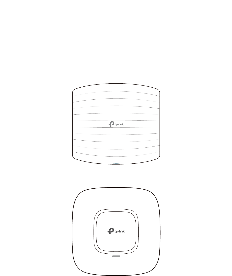
The following figure shows the top view of EAP225/EAP320/EAP330:
The following figure shows the top view of EAP110/EAP115/EAP245:
3
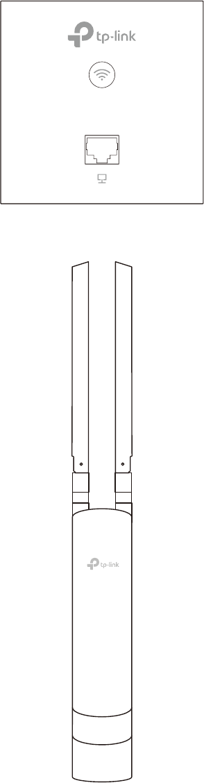
The following figure shows the front view of EAP115-Wall:
The following figure shows the front view of EAP110-Outdoor/EAP225-Outdoor:

4
1 Quick Start
This chapter introduces how to build a wireless network using the EAPs and how to
complete the basic settings. Follow the steps below:
1.
Determine the Management Method
2. Build the Network Topology
3. Log in to the EAP
4. Edit the SSID
5. Configure and Manage the EAP
5
1.1 'HWHUPLQHWKH0DQDJHPHQW0HWKRG
Before building the wireless network, choose a proper method to manage the EAP based
on your actual network situation. There are two methods: via EAP Controller and via the
web page of the EAP.
9LD($3&RQWUROOHU
If you want to establish a large-scale wireless network and have mass EAPs to be
managed, we recommend that you use EAP Controller to centrally manage the EAPs. In
such case, the EAPs work in FIT mode.
For detailed instructions about the network topology in such situation and how to use EAP
Controller, refer to the User Guide of EAP Controller. To download EAP Controller and its
User Guide, go to
http://www.tp-link.com/en/download/EAP-Controller.html
.
9LDWKH:HE3DJHRIWKH($3
If you have a relatively small-sized wireless network and only one or just a small number
of EAPs need to be managed, you can directly use the web browser to manage each EAP
on its own management web page. In such case, the EAP works in Standalone mode (FAT
mode), which means that it works independently as a standalone access point.
This User Guide introduces how to configure the Standalone EAP on its web page.
Note:
The web page of an EAP is inaccessible while it is managed by EAP Controller. To turn the EAP back
to Standalone mode and access its web page, you can Forget the EAP on EAP Controller to reset
the EAP or simply close EAP Controller.
6
1.2 %XLOGWKH1HWZRUN7RSRORJ\
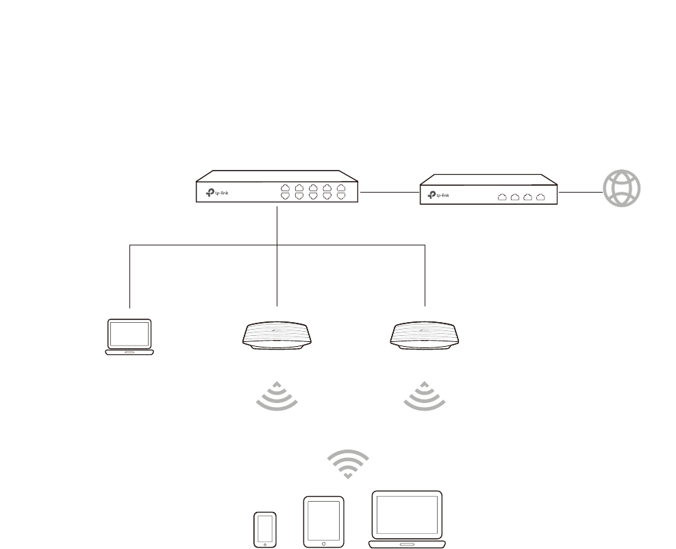
To manage the EAPs in Standalone mode, refer to the following topology.
EAPEAPPC
IP: 192.168.0.100
Switch Router (DHCP Server)
LAN: 192.168.0.1 Internet
Clients
• The router is the gateway of the network, and devices in the LAN surf the internet via
the router. At the same time, the router acts as a DHCP server to assign dynamic IP
addresses to the EAPs and clients.
• The layer 2 switch is connected to the LAN interface of the router.
• The PC and the EAPs are all connected to the layer 2 switch. Since the PC and the EAPs
are in the same network segment, the PC can log in to the web pages of the EAPs and
manage them.
1.3 /RJLQWRWKH($3
There are two methods to log in to the EAP. You can choose one as you like:
Log in via the
Domain Name
and
Log in via the IP Address of the EAP
.
Note:
EAP320 and EAP330 are not currently available for login via domain name.
7
/RJLQYLDWKH'RPDLQ1DPH
In this method, you needn't know the IP address of the EAP, but you need to prepare a
wireless client device, such as a wireless laptop. Follow the steps below to log in to the
EAP wirelessly:
̝Find the default SSID of the EAP. The SSID is printed on the product label at the bottom
of the device, and the format is 73/,1.B*+]*+]B;;;;;;.
̝Search the default SSID using your wireless client device and connect to the wireless
network of the EAP.
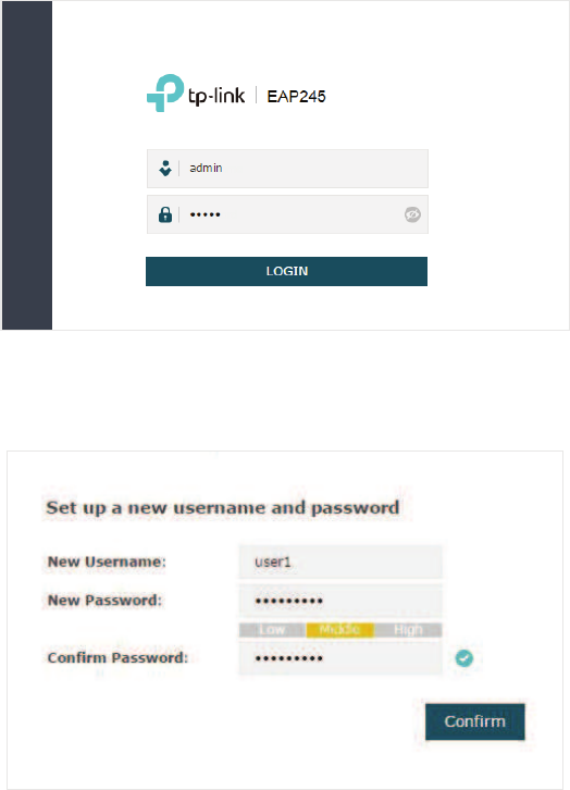
̝Launch a web browser on the client device and enter KWWSWSOLQNHDSQHW in the
address bar to load the login page of the EAP. Use DGPLQ for both of the username and
password to log in.
̝In the pop-up window, configure a new username and a new password for your user
account.
8
̝Use the new username and password to log in.
Tips:
To facilitate access to the EAP via a wired device, you can set a static IP address for the EAP and
remember it well or write it down. But make sure that this IP address is not being used in the same
LAN. For detailed instructions about how to set a static IP address for the EAP, refer to
Configure
the IP Address of the EAP
.
/RJLQYLDWKH,3$GGUHVVRIWKH($3
To log in to the EAP through the Ethernet cable, you need to know the IP address of the
EAP. Follow the steps below to log in via the IP address of the EAP:
̝Get the IP address of the EAP. There are two methods.
• Log in to the router which acts as the DHCP server. In the DHCP client list, find the IP
address of your EAP according to its MAC address. The MAC address can be found
at the bottom of the EAP.
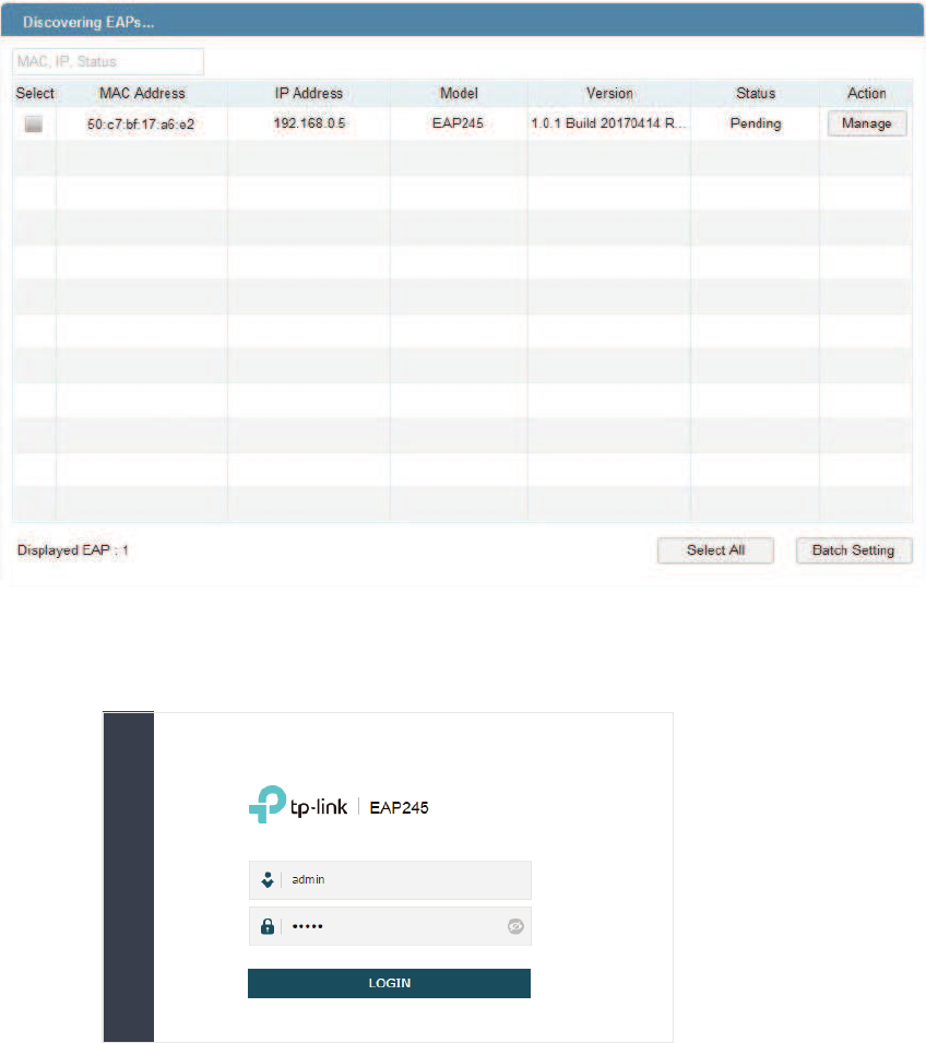
• Go to
http://www.tp-link.com/en/download/EAP-Controller.html#EAP_Discovery_
Tool
to download EAP Discovery Utility. EAP Discovery Utility is a software that can
scan all EAPs in the same network segment. Install and launch EAP Discovery Utility
9
on the PC, and find the IP address of the EAP. In the following figure, the IP address of
the EAP is 192.168.0.5.
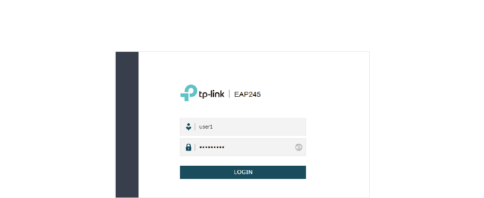
̝Launch a web browser and enter 192.168.0.5 in the address bar to load the login page
of the EAP. Use DGPLQfor both of the username and password to log in.
10
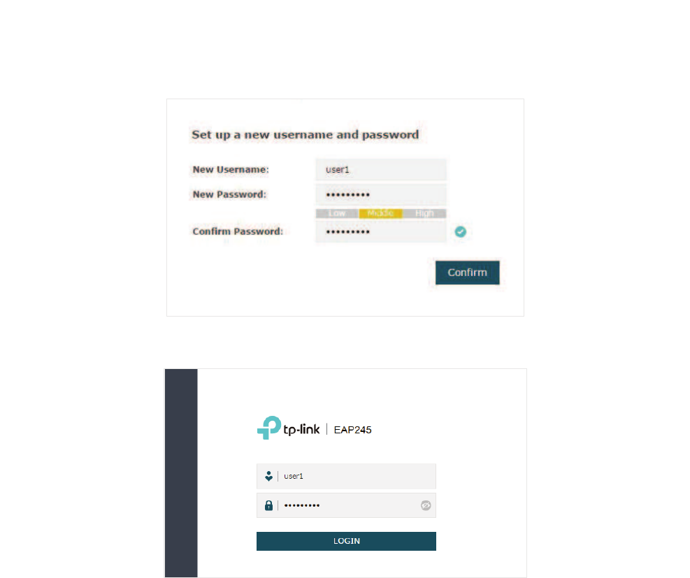
̝In the pop-up window, configure a new username and a new password for your user
account.
̝Use the new username and password to log in.
Tips:
To facilitate access to the EAP via a wired device, you can set a static IP address for the EAP and
remember it well or write it down. But make sure that this IP address is not being used in the same
LAN. For detailed instructions about how to set a static IP address for the EAP, refer to
Configure
the IP Address of the EAP
.
1.4 Edit the SSID
By default, the dual-band EAP has two default SSIDs named 73/,1.B*+]B;;;;;;
and73/,1.B*+]B;;;;;;on the 2.4GHz band and 5GHz band, and the single-band
EAP has a default SSID named 73/,1.B*+]B;;;;;; on the 2.4GHz band.
The default SSID has no password, so anyone can access the network without
authentication. If your network is a private network, for security, we recommend that you
change the SSID configuration immediately after login.
Follow the steps below to edit the default SSID:
11
̝Go to the :LUHOHVV!:LUHOHVV6HWWLQJV page. In the SSIDs section, click in the
0RGLI\ column of the SSID entry.
12
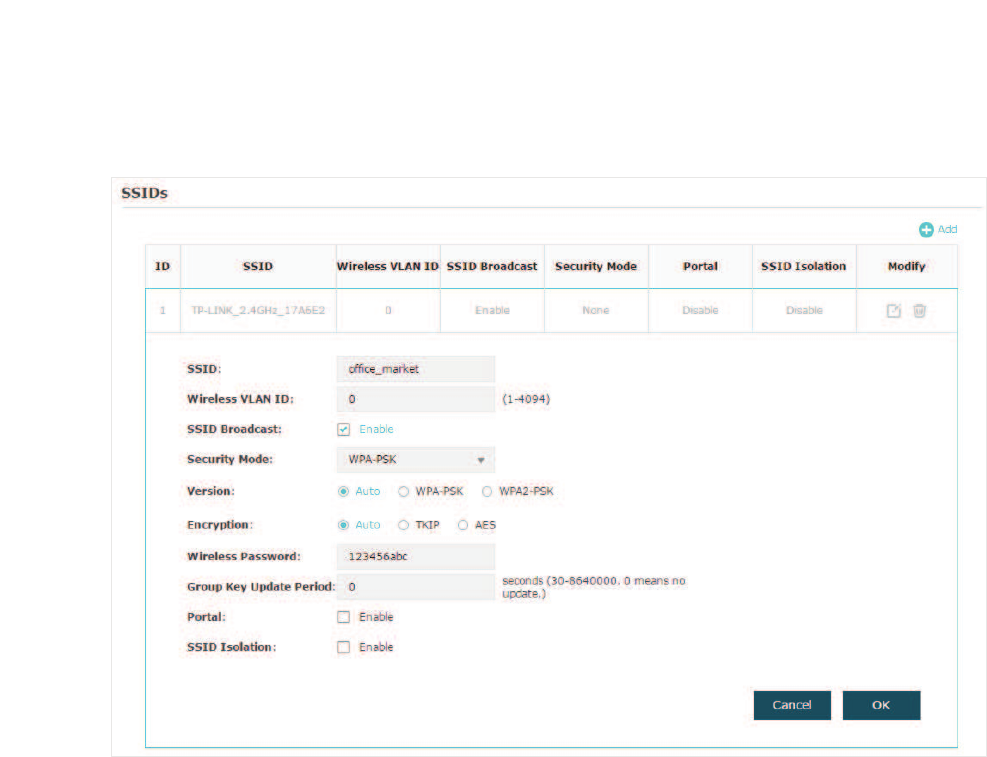
̝The following page will appear. Change Security Mode from None to :(3:3$
(QWHUSULVH or :3$36.. Configure the related parameters and click 2.. We
recommend that you choose :3$36.. For details, refer to
Configure SSIDs
.
Tips:
g If needed, you can also create more new SSIDs. For detailed instructions about how to create
new SSIDs, refer to
Configure SSIDs
.
g If your EAP is a dual-band EAP, remember to configure the SSID of the 5GHz band in the same
way.
13
1.5 &RQILJXUHDQG0DQDJHWKH($3
After all the steps above are completed, the legal wireless clients can enjoy the internet via
the EAP. Additionally, you can configure the advanced functions of the EAP according to
your need, and manage it conveniently on the web page.
On the top of the page, you can click to log out and click to open the technical
support website.
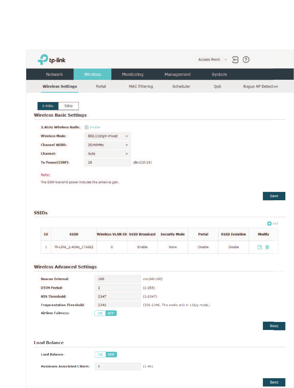
There are five tabs: 1HWZRUN:LUHOHVV 0RQLWRULQJ0DQDJHPHQW and 6\VWHP. The
following table introduces what you can configure under each tab.
Network You can configure the IP address of the EAP.
Wireless You can configure the wireless parameters and the advanced features, such
as Portal, MAC Filtering, Scheduler, QoS and Rogue AP Detection.
Monitoring You can view the information of the EAP, SSIDs and clients.
Management You can manage the EAP using the management features, such as System
Logs, Web Server, Management Access, Management VLAN and SNMP.
System You can configure the system parameters, including the login account and
the system time. In addition, you can reboot and reset the EAP, backup and
restore the configuration, and upgrade the EAP using the new firmware file.

14
2 &RQƮJXUHWKH1HWZRUN
This chapter introduces how to configure the network parameters and the advanced
features of the EAP, including:
̝
gConfigure the IP Address of the EAP
̝
gConfigure the Wireless Parameters
̝
gConfigure Portal Authentication
̝
gConfigure MAC Filtering
̝
gConfigure Scheduler
̝
gConfigure QoS
̝
gConfigure Rogue AP Detection
15
2.1 &RQILJXUHWKH,3$GGUHVVRIWKH($3
The IP address of the EAP can be a dynamic IP address assigned by the DHCP server or
a static IP address manually specified by yourself. By default, the EAP gets a dynamic IP
address from the DHCP server. You can also specify a static IP address according to your
needs.
Tips:
For detailed introduction about how to find the dynamic IP address of the EAP, refer to
Log in via the
IP Address of the EAP
.
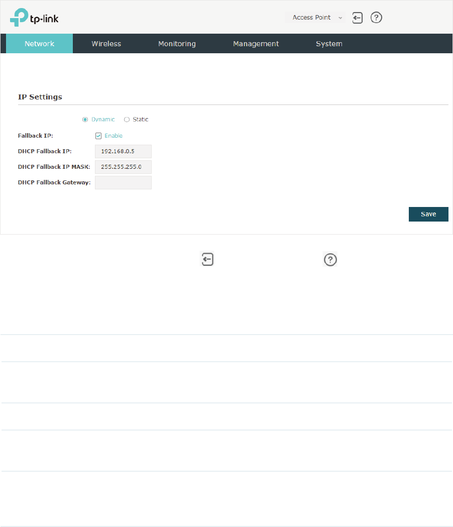
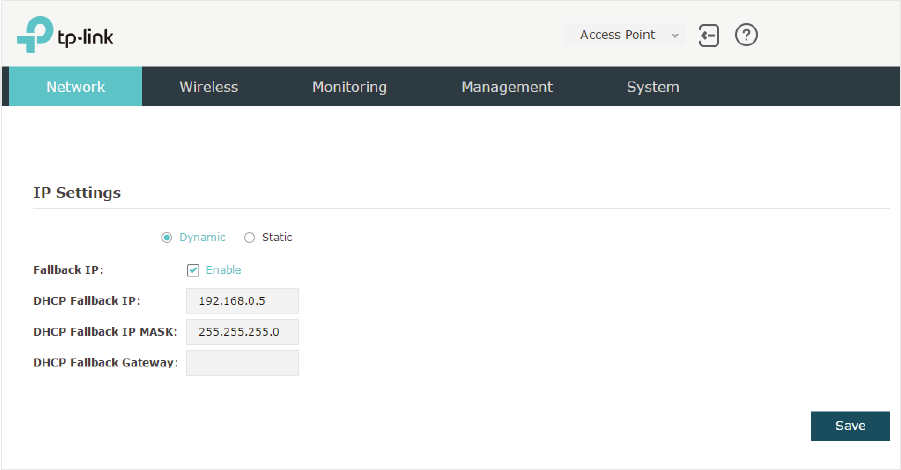
To configure the IP address of the EAP, go to the 1HWZRUN page.
Follow the steps below to configure the IP address of the EAP:
̝Choose your desired IP address mode: '\QDPLF or 6WDWLF.
̝Configure the related parameters according to your selection.
16
g'\QDPLF
If you choose Dynamic as the IP address mode, make sure that there is a reachable
DHCP server on your network and the DHCP sever is properly configured to assign IP
address and the other network parameters to the EAP.
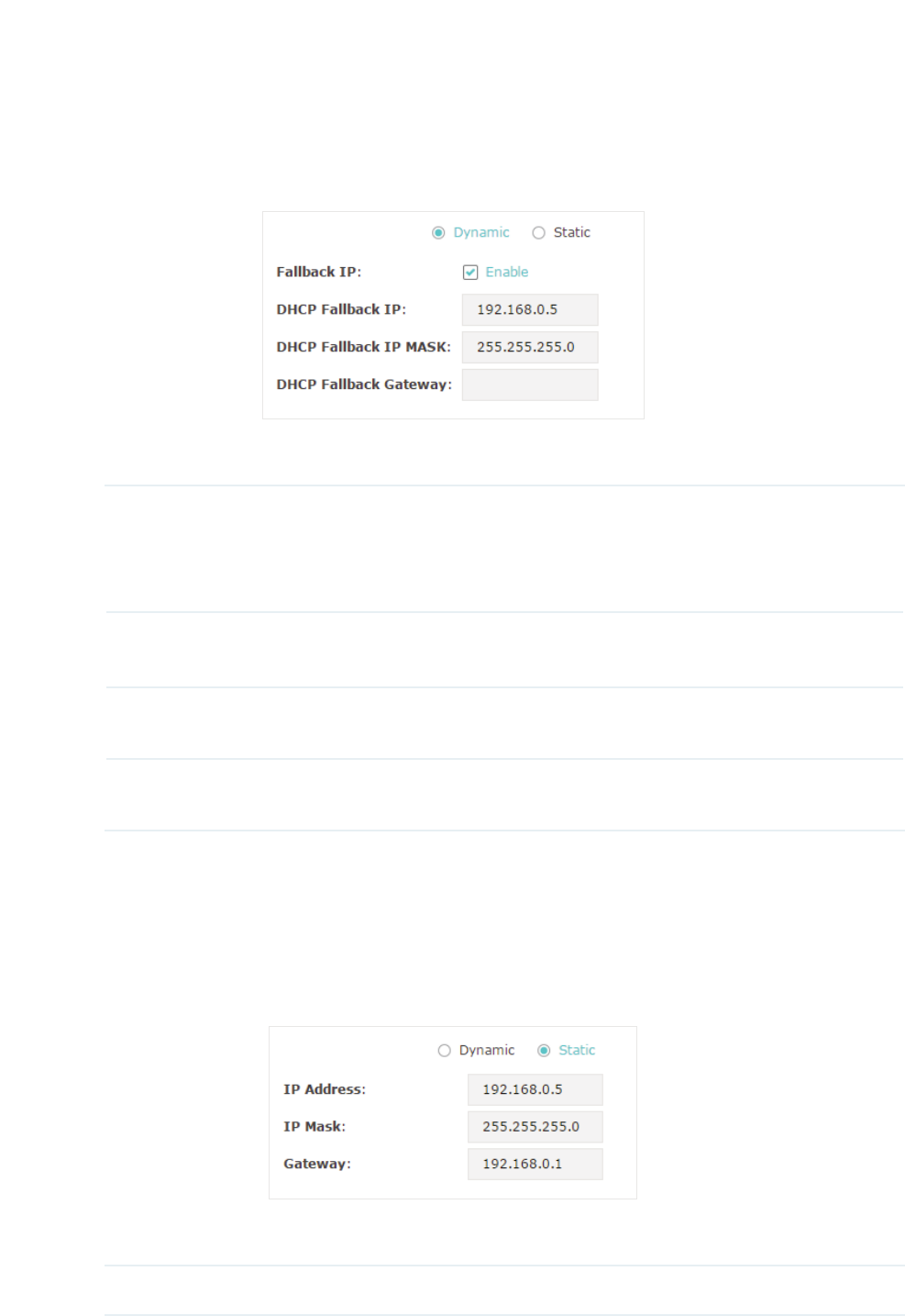
For network stability, you can also configure the fallback IP parameters for the EAP:
Fallback IP With the fallback IP configured, if the EAP fails to get an IP address from a
DHCP server within 10 seconds, the fallback IP will work as the IP address
of the EAP. After that, however, the EAP will keep trying to obtain an IP
address from the DHCP server until it succeeds.
DHCP Fallback
IP
Specify a fallback IP address for the EAP. Make sure that this IP address
is not being used by any other device in the same LAN.
DHCP Fallback
IP MASK
Specify the network mask of the fallback IP.
DHCP Fallback
Gateway
Specify the network gateway.
g6WDWLF
If you choose Static as the IP address mode, you need to manually specify an IP
address and the related network parameters for the EAP. Make sure that the specified
IP address is not being used by any other device in the same LAN.
Configure the IP address and network parameters as the following table shows:
IP Address Specify a static IP address for the EAP.

17
IP Mask Specify the network mask.
Gateway Specify the network gateway.
̝Click 6DYH.
18
2.2 &RQILJXUHWKH:LUHOHVV3DUDPHWHUV
To configure the wireless parameters, go to the :LUHOHVV!:LUHOHVV6HWWLQJVpage.
The following sections introduce these contents:
Configure Basic Wireless Settings
,
Configure SSIDs
,
Cofigure Wireless Advanced Settings
and
Configure Load Balance
.
19
Note:
g For a dual-band EAP, there are two bands: 2.4GHz and 5GHz. The wireless parameters are
separately set on each band. You can click to select a band and configure the wireless
parameters on this band.
g The following figures take 2.4GHz as an example.
&RQILJXUH%DVLF:LUHOHVV6HWWLQJV
Proper wireless parameters can improve the quality of your wireless network. This section
introduces how to configure the basic wireless parameters.
Follow the steps below to complete the basic wireless settings:
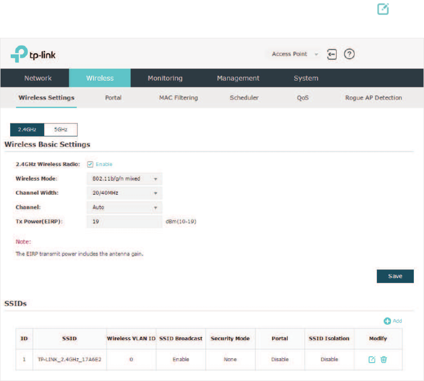
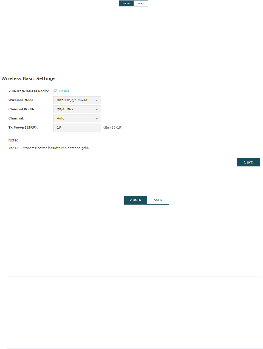
̝If your EAP is a dual-band device, click to choose a frequency band to
be configured.
̝In the :LUHOHVV%DVLF6HWWLQJV section, configure the following parameters:
2.4GHz Wireless
Radio/5GHz
Wireless Radio
Check the box to enable 2.4GHz/5GHz Wireless Radio. By default, it is
enabled.
Only when this option is enabled will the wireless radio on 2.4GHz/5GHz
band works.
Wireless Mode Select the protocol standard for the wireless network.
For 2.4GHz network, we recommend that you selectEJQ. In
this way, clients supporting any one of these modes can access your
wireless network.
For 5GHz network, we recommend that you select QDF RU
DQDF. In this way, clients supporting any one of these modes
can access your wireless network.

20
Channel Width Select the channel width.
According to IEEE 802.11n standard, using a higher bandwidth can
increase wireless throughput. However, you may choose a lower
bandwidth due to the following reasons:
gTo increase the available number of channels within the limited total
bandwidth.
gTo avoid interference from overlapping channels occupied by other
devices in the environment.
gLower bandwidth can concentrate higher transmit power, increasing
stability of wireless links over long distances.
Channel Select the channel used by the EAP. For example, 1/2412MHz means
that the channel is 1 and the frequency is 2412MHz.
By default, the channel is automatically selected, and we recommend
that you keep the default setting.
Tx Power (EIRP) Specify the transmit power value.
If this value is set to be larger than the maximum transmit power that is
allowed by the local regulation, the regulated maximum transmit power
will be applied in the actual situation.
1RWH
In most cases, it is unnecessary to use the maximum transmit
power. Specifying a larger transmit power than needed may cause
interference to the neighborhood. Also it consumes more power and
reduces longevity of the device.
̝Click 6DYH
21
&RQILJXUH66,'V
SSID (Service Set Identifier) is used as an identifier for a wireless LAN, and is commonly
called as the “network name“. Clients can find and access the wireless network through
the SSID. For one EAP, you can build up to eight SSIDs per frequency band.
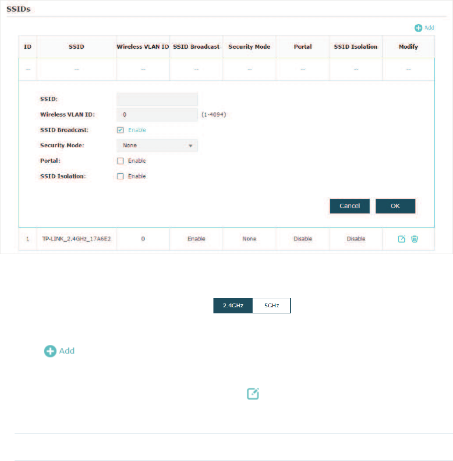
Follow the steps below to create an SSID on the EAP:
̝If your EAP is a dual-band device, click to choose a frequency band on
which the new SSID will be created.
̝Click to add a new SSID on the chosen band.
Tips:
If there are SSIDs already in the list, you can also click to edit the specific SSID.
̝Configure the following required parameters for this SSID:
SSID Specify a name for the wireless network.

22
Wireless VLAN
ID
Set a VLAN ID for the wireless network. It supports maximum 8 VLANs
per frequency band.
With this feature, the EAP can work together with the switches
supporting 802.1Q VLAN. The EAP adds different VLAN tags to the
clients which are connected to the corresponding wireless network. The
clients in different VLANs cannot directly communicate with each other.
VLAN 0 means that the EAP does not add any VLAN tag to the clients
which are connected to this wireless network.
1RWH
Clients connected to the EAP via Ethernet cable do not belong
to any VLAN. Thus wired client can communicate with all the wireless
clients despite the VLAN settings.
SSID Broadcast With the option enabled, EAP will broadcast the SSID to the nearby
hosts, so that those hosts can find the wireless network identified by
this SSID. If this option is disabled, users must enter the SSID manually
to connect to the EAP.
Security Mode Select the security mode of the wireless network. There are four
options:
1RQH Clients can access the wireless network without authentication.
:(3:3$(QWHUSULVH:3$36.: Clients need to pass the authentication
before accessing the wireless network. For network security, we
recommend that you encrypt your wireless network. The following
sections will introduce how to configure these security modes.
Portal With this option enabled, the Portal configuration will be applied to this
wireless network.
Portal provides authentication service for the clients who just need
temporary access to the wireless network, such as the customers in a
shopping mall or in a restaurant. Portal also provides a way for vendors
and companies to put their advertisements on the authentication
page. For detailed instructions about Portal, refer to
Configure Portal
Authentication
.
SSID Isolation With this option enabled, the devices connected to the same SSID
cannot communicate with each other.
̝Click 2. to create the SSID.
Following is the detailed instructions about how to configure
WEP
,
WPA-Enterprise
and
WPA-PSK
.
̝
g:(3
WEP (Wired Equivalent Privacy) is a traditional encryption method. It has been proved
that WEP has security flaws and can easily be cracked, so WEP cannot provide effective
protection for wireless networks. Since WPA-PSK and WPA-Enterprise are much safer
23
than WEP, we recommend that you choose WPA-PSK or WPA-Enterprise if your clients
also support them.
Note:
WEP is not supported in 802.11n mode or 802.11ac mode. If WEP is applied in 802.11n, 802.11 ac
or 802.11n/ac mixed mode, the clients may not be able to access the wireless network. If WEP is
applied in 802.11b/g/n mode (2.4GHz) or 802.11a/n (5GHz), the EAP may work at a low transmission
rate.
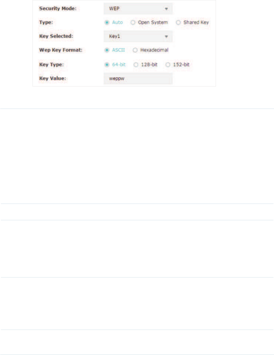
The following table detailedly introduces how to configure each item:
Type Select the authentication type for WEP.
$XWR The EAP can select Open System or Shared Key automatically based
on the wireless capability and request of the clients.
2SHQ6\VWHPClients can pass the authentication and associate with
the wireless network without password. However, correct password is
necessary for data transmission.
6KDUHG .H\Clients have to input the correct password to pass the
authentication, otherwise the clients cannot associate with the wireless
network or transmit data.
Key Selected Select one key to specify. You can configure four keys at most.
WEP Key Format Select ASCII or Hexadecimal as the WEP key format.
$6&,,With this format selected, the WEP key can be any combination of
keyboard characters of the specified length.
+H[DGHFLPDO With this format selected, the WEP key can be any
combination of hexadecimal digits (0-9, a-f, A-F) with the specified length.
Key Type Select the WEP key length for encryption.
%LWEnter 10 hexadecimal digits or 5 ASCII characters.
%LWEnter 26 hexadecimal digits or 13 ASCII characters.
%LW Enter 32 hexadecimal digits or 16 ASCII characters.
Key Value Enter the WEP keys. The length and valid characters are determined by the
key format and key type.
24
̝
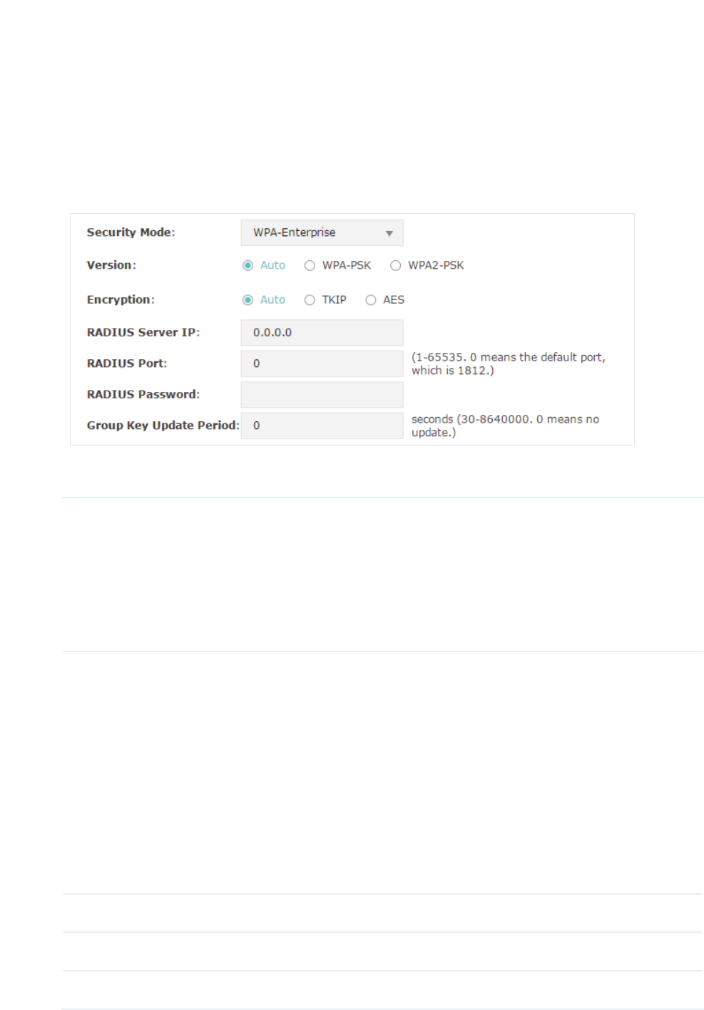
g:3$(QWHUSULVH
WPA-Enterprise (Wi-Fi Protected Access-Enterprise) is a safer encryption method
compared with WEP and WAP-PSK. It requires a RADIUS server to authenticate the clients
via 802.1X and EAP (Extensible Authentication Protocol). WPA-Enterprise can generate
different passwords for different clients, which ensures higher network security. But it also
costs more to maintain the network, so it is more suitable for business networks.
The following table introduces how to configure each item:
Version Select the version of WPA-Enterprise.
$XWRThe EAP will automatically choose the version used by each client
device.
:3$:3$They’re two versions of WPA security mode. WPA2 is an
update of WPA. Compared with WPA, WPA2 introduces AES algorithm
and CCMP encryption. Theoretically, WPA2 is securer than WPA.
Encryption Select the Encryption type.
$XWR The default setting is Auto and the EAP will select TKIP or AES
automatically based on the client device’s request.
7.,3 Temporal Key Integrity Protocol. TKIP is not supported in 802.11n
mode, 802.11ac mode or 802.11n/ac mixed mode. If TKIP is applied in
802.11n, 802.11 ac or 802.11n/ac mixed mode, the clients may not be
able to access the wireless network. If TKIP is applied in 11b/g/n mode
(2.4GHz) or 11a/n mode(5GHz), the device may work at a low transmission
rate.
$(6 Advanced Encryption Standard. It is securer than TKIP.
RADIUS Server IP Enter the IP address of the Radius Server.
RADIUS Port Enter the port number of the Radius Server.
RADIUS Password Enter the shared secret key of the Radius server.
25
Group Key Update
Period
Specify an update period of the encryption key. The update period
instructs how often the EAP should change the encryption key. 0 means
that the encryption key does not change at anytime.
̝
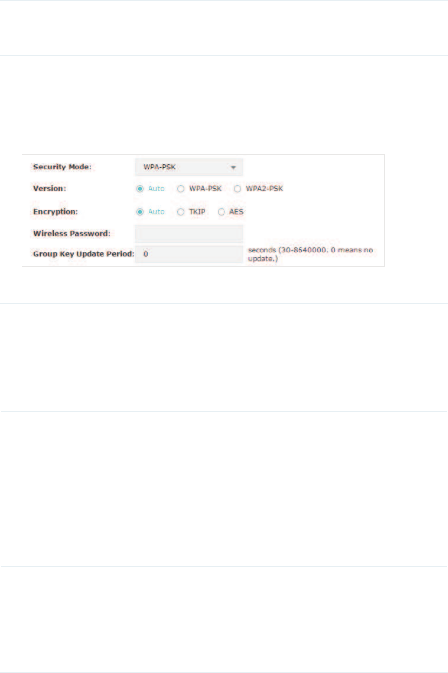
g:3$36.
WPA-PSK (Wi-Fi Protected Access-PSK) is based on a pre-shared key. It is characterized
by high safety and simple settings, so it is mostly used by common households and small
businesses.
The following table introduces how to configure each item:
Version Select the version of WPA-Enterprise.
$XWRThe EAP will automatically choose the version used by each client
device.
:3$36.:3$36.They’re two versions of WPA-PSK security mode.
WPA2-PSK is an update of WPA-PSK. Compared with WPA, Theoretically,
WPA2 is securer than WPA.
Encryption Select the Encryption type.
$XWR The default setting is Auto and the EAP will select TKIP or AES
automatically based on the client device’s request.
7.,3 Temporal Key Integrity Protocol. TKIP is not supported in 802.11n
mode, 802.11ac mode or 802.11n/ac mixed mode. If TKIP is applied in
802.11n, 802.11 ac or 802.11n/ac mixed mode, the clients may not be able
to access the wireless network. If TKIP is applied in 11b/g/n mode (2.4GHz)
or 11a/n mode(5GHz), the device may work at a low transmission rate.
$(6 Advanced Encryption Standard. It is securer than TKIP.
Wireless
Password
Configure the wireless password with ASCII or Hexadecimal characters.
gFor ASCII, the length should be between 8 and 63 and the valid
characters contain numbers, letters (case-sensitive) and common
punctuations.
gFor Hexadecimal, the length should be between 8 and 64, and the valid
characters contain: 0-9, a-f, A-F.
26
Group Key
Update Period
Specify an update period of the encryption key. The update period instructs
how often the EAP should change the encryption key. 0 means that the
encryption key does not change at anytime.
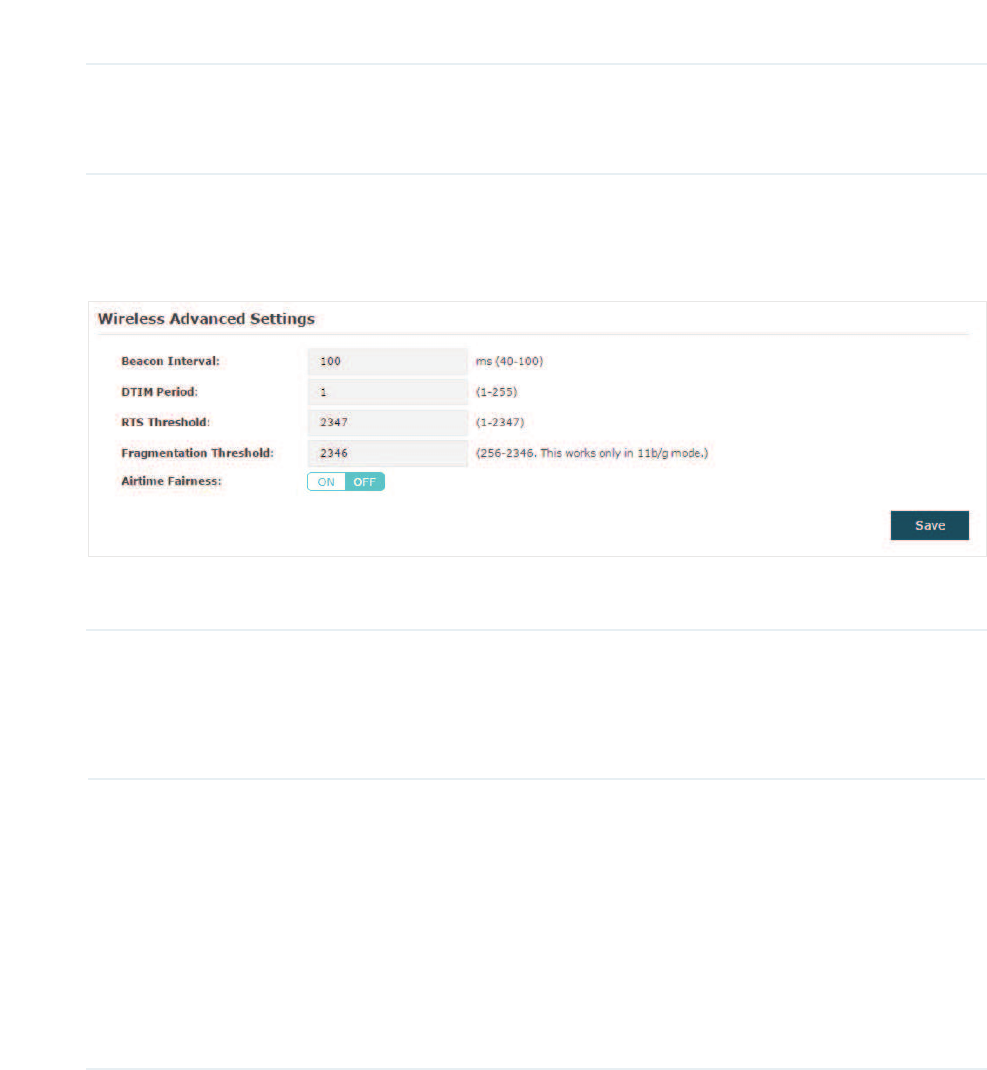
&RILJXUH:LUHOHVV$GYDQFHG6HWWLQJV
Configure the advanced wireless parameters of the EAP and click 6DYH.
The following table introduces how to configure each item:
Beacon Interval Beacons are transmitted periodically by the EAP device to announce the
presence of a wireless network for the clients. %HDFRQ,QWHUYDO determines
the time interval of the beacons sent by the EAP device.
You can specify a value between 40 and 100ms. The default is 100ms.
DTIM Period The DTIM (Delivery Traffic Indication Message) is contained in some
Beacon frames. It indicates whether the EAP device has buffered data for
client devices. The '7,03HULRG indicates how often the clients served
by this EAP device should check for buffered data still on the EAP device
awaiting pickup.
You can specify the value between 1-255 Beacon Intervals. The default
value is 1, indicating that clients check for buffered data at every beacon.
An excessive DTIM interval may reduce the performance of multicast
applications, so we recommend you keep the default value.

27
RTS Threshold RTS/CTS (Request to Send/Clear to Send) is used to improve the data
transmission efficiency of the network with hidden nodes, especially when
there are lots of large packets to be transmitted.
When the size of a data packet is larger than the 5767KUHVKROG, the RTS/
CTS mechanism will be activated. With this mechanism activated, before
sending a data packet, the client will send an RTS packet to the EAP to
request data transmitting. And then the EAP will send CTS packet to inform
other clients to delay their data transmitting. In this way, packet collisions
can be avoided.
For a busy network with hidden nodes, a low threshold value will help
reduce interference and packet collisions. But for a not-so-busy network, a
too low threshold value will cause bandwidth wasting and reduce the data
throughput. The recommended and default value is 2347 bytes.
Fragmentation
Threshold
The fragmentation function can limit the size of packets transmitted over
the network. If the size of a packet exceeds the )UDJPHQWDWLRQ7KUHVKROG,
the fragmentation function is activated and the packet will be fragmented
into several packets.
Fragmentation helps improve network performance if properly configured.
However, a too low fragmentation threshold may result in poor wireless
performance caused by the extra work of dividing up and reassembling
of frames and increased message traffic. The recommended and default
value is 2346 bytes.
Airtime Fairness Only EAP320 and EAP330 support this feature.
With this option enabled, each client connected to the EAP can get the
same amount of time to transmit data, avoiding low-data-rate clients to
occupy too much network bandwidth.
Compared with the relatively new client devices, some legacy client
devices support slower wireless rate. If they communicate with the
same EAP, the slower clients take more time to transmit and receive
data compared with the faster clients. As a result, the overall wireless
throughput of the network decreases. So under such circumstance, we
recommend that you enable this feature to ensure the data transmission
time for the faster clients. In this way, the network overall throughput can
be improved.
28
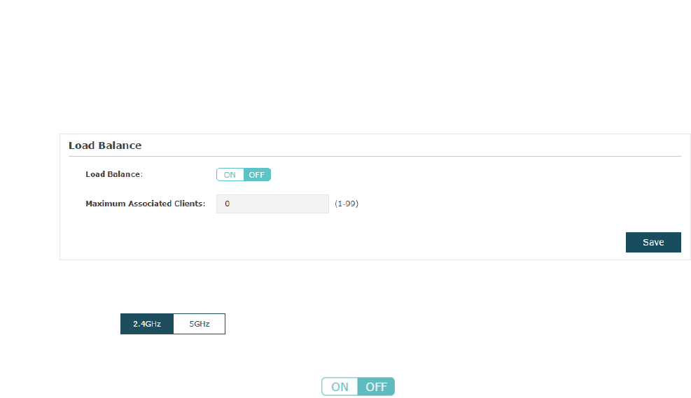
&RQILJXUH/RDG%DODQFH
With the Load Balance feature, you can limit the maximum number of clients who can
access the EAP. In this way, you can achieve rational use of network resources.
Follow the steps below to configure Load Balance:
̝Click to choose a frequency band on which the load balance feature will
take effect.
̝In the /RDG%DODQFH section, click to enable this feature. The ON button with
cyan background color indicates this feature is enabled.
̝Specify the maximum number of clients who can connect to the EAP at the same time.
While the number of connected clients has reached the limit and there are more clients
requesting to access the network, the EAP will disconnect those with weaker signals.
̝Click 6DYH.
2.3 &RQILJXUH3RUWDO$XWKHQWLFDWLRQ
Portal authentication provides authentication service to the clients that only need
temporary access to the wireless network, such as the customers in a restaurant or in a
supermarket. To access the network, these clients need to enter the authentication login
page and use the correct login information to pass the authentication. In addition, you can
customize the authentication login page and specify a URL which the authenticated clients
will be redirected to.
In this module, you can also configure Free Authentication Policy, which allows the specific
clients to access the specific network resources without authentication.
29
To configure portal authentication, go to the :LUHOHVV!3RUWDOpage.
&RQILJXUH3RUWDO
Three portal authentication types are available:
No Authentication
,
Local Password
and
External Radius Server
. The following sections introduce how to configure each
authentication type.
30
̝
g1R$XWKHQWLFDWLRQ
With this authentication type configured, clients can pass the authentication and access
the network without providing any login information. They only need to accept the term of
use on the authentication page.
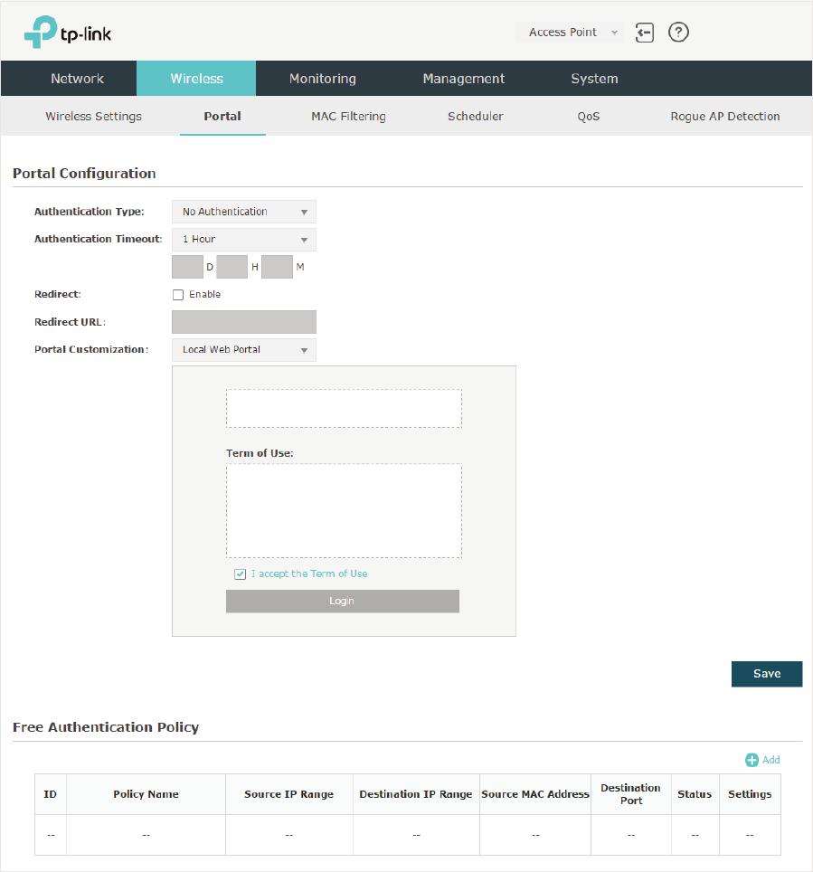
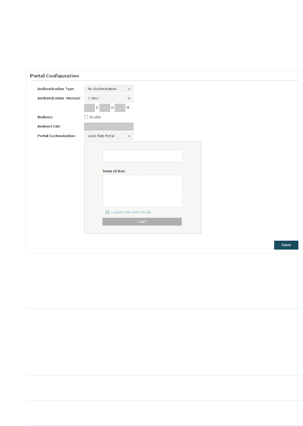
Follow the steps below to configure No Authentication as the portal authentication type:
̝Select 1R$XWKHQWLFDWLRQ as the authentication type.
̝Configure the relevant parameters as the following table shows:
Authentication
Timeout
Specify the value of authentication timeout.
A client’s authentication will expire after the authentication timeout and
the client needs to log in to the authentication page again to access the
network.
Options include+RXU+RXUV+RXUV'D\V and Custom. With
Custom selected, you can customize the time in days, hours, and minutes.
Redirect With this function configured, the newly authenticated client will be
redirected to the specific URL.
Redirect URL With5HGLUHFW enabled, you also need to enter the URL in this field. The
newly authenticated client will be redirected to this URL.
31
Portal
Customization
Configure the authentication page. /RFDO:HE3RUWDO is the only available
option in this authentication type. Enter the title and term of use in the two
boxes.
The EAP uses its built-in web server to provide this authentication page for
clients. To pass the authentication, clients only need to check the box of I
DFFHSWWKH7HUPRI8VHand click the /RJLQbutton.
̝Click 6DYH.
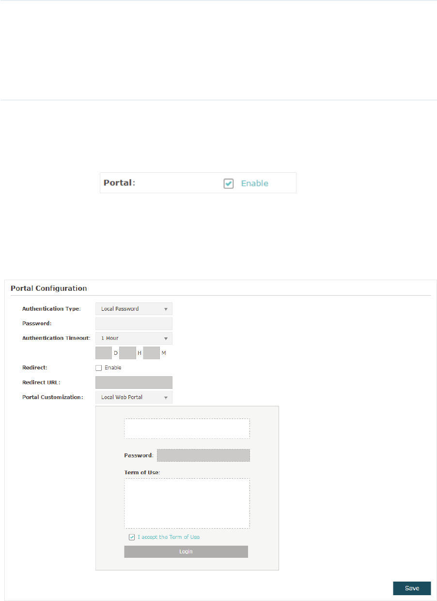
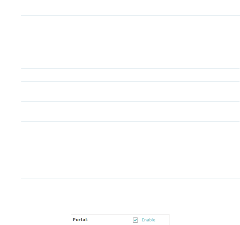
̝Go to the :LUHOHVV!:LUHOHVV 6HWWLQJV page and enable the 3RUWDOoption for the
specific SSID. Then the portal authentication feature will take effect on this SSID.
̝
g/RFDO3DVVZRUG
With this authentication type configured, clients are required to provide the correct
password to pass the authentication.
Follow the steps below to configure Local Password as the portal authentication type:
̝Select/RFDO3DVVZRUG as the authentication type.
̝Configure the relevant parameters as the following table shows:
32
Authentication
Timeout
Specify the value of authentication timeout.
A client’s authentication will expire after the authentication timeout and
the client needs to log in to the authentication page again to access the
network.
Options include+RXU+RXUV+RXUV'D\V and Custom. With
Custom selected, you can customize the time in days, hours, and minutes.
Password Specify a password for authentication.
Redirect With this function configured, the newly authenticated client will be
redirected to the specific URL.
Redirect URL With 5HGLUHFW enabled, you also need to enter the URL in this field. The
newly authenticated client will be redirected to this URL.
Portal
Customization
Configure the authentication page. /RFDO:HE3RUWDO is the only available
option is this authentication type. Enter the title and term of use in the two
boxes.
The EAP uses its built-in web server to provide this authentication page
for clients. To pass the authentication, clients need to provide the correct
password in the 3DVVZRUG field, check the box of,DFFHSWWKH7HUPRI8VH
and click the /RJLQ button.
̝Click 6DYH.
̝Go to the :LUHOHVV!:LUHOHVV 6HWWLQJVpage and enable the 3RUWDOoption for the
specific SSID. Then the portal authentication feature will take effect on this SSID.
33
̝
g([WHUQDO5DGLXV6HUYHU
If you have a RADIUS server on the network to authenticate the clients, you can select
([WHUQDO5DGLXV6HUYHU. Clients need to provide the correct login information to pass the
authentication.
Follow the steps below to configure External Radius Server as the portal authentication
type:
̝Build a Radius server on the network and make sure that it is reachable by the EAP.
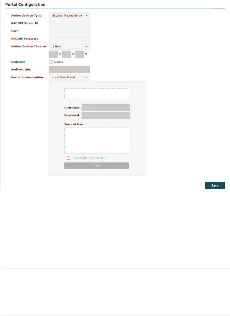
̝Go to the 3RUWDOconfiguration page on the EAP. Select ([WHUQDO5DGLXV6HUYHU as the
authentication type.
3. Configure the relevant parameters as the following table shows:
RADIUS Server IP Enter the IP address of RADIUS server.
Port Enter the port of the RADIUS server.
RADIUS
Password
Enter the password of the RADIUS server.
34
Authentication
Timeout
Specify the value of authentication timeout.
A client’s authentication will expire after the authentication timeout and
the client needs to log in to the authentication page again to access the
network.
Options include+RXU+RXUV+RXUV'D\V and Custom. With
Custom selected, you can customize the time in days, hours, and minutes.
Redirect With this function configured, the newly authenticated client will be
redirected to the specific URL.
Redirect URL With 5HGLUHFW enabled, you also need to enter the URL in this field. The
newly authenticated client will be redirected to this URL.
Portal
Customization
Configure the authentication page. There are two options: /RFDO:HE
3RUWDO and ([WHUQDO:HE3RUWDO.
gLocal Web Portal
Enter the title and term of use in the two boxes. The EAP uses its built-
in web server to provide this authentication page for clients. To pass
the authentication, clients need to provide the correct username and
password in the 8VHUQDPHand 3DVVZRUGfields, check the box of,DFFHSW
the Term of Use and click the/RJLQbutton.
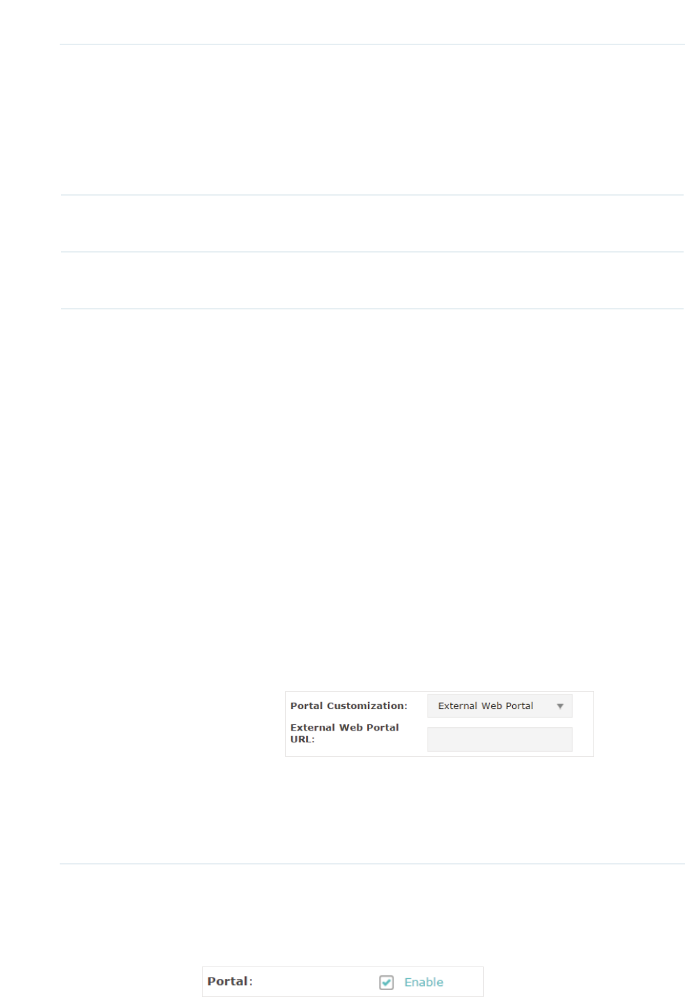
gExternal Web Portal
With External Web Portal configured, the authentication page will be
provided by the web portal server built on the network. To configure
External Web Portal, you need to complete the following configurations:
̝Build an external web portal server on your network and make sure that
it is reachable by the EAP.
̝On this configuration page, enter the URL of the authentication page
provided by the external portal server.
̝Add the external web portal server to the )UHH$XWKHQWLFDWLRQ3ROLF\
list. In this way, clients can access the web portal server before
authenticated. For details about how to configure Free Authentication
Policy, refer to
Configure Free Authentication Policy
.
̝Click6DYH.
̝Go to the :LUHOHVV!:LUHOHVV 6HWWLQJV page and enable the 3RUWDOoption for the
specific SSID. Then the portal authentication feature will take effect on this SSID.
35
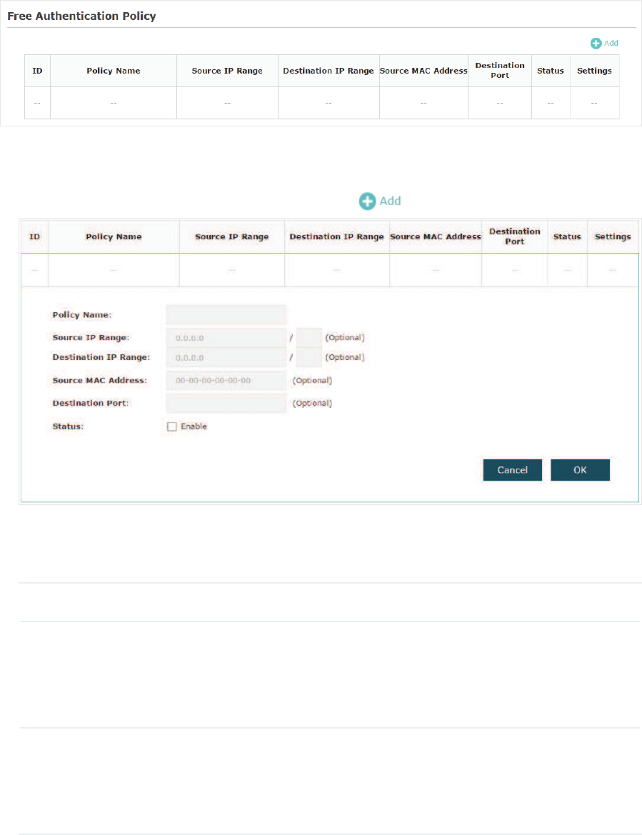
&RQILJXUH)UHH$XWKHQWLFDWLRQ3ROLF\
Free Authentication Policy allows some specific clients to access the specific network
resources without authentication. For example, you can set a free authentication policy
to allow clients to visit the external web portal server before authenticated. In this way,
the clients can visit the login page provided by the web portal server and then pass the
subsequent authentication process.
Follow the steps below to add free authentication policy.
̝In the )UHH$XWKHQWLFDWLRQ3ROLF\ section, click to load the following page.
̝Configure the following parameters. When all the configured conditions are met, the
client can access the network without authentication.
Policy Name Specify a name for the policy.
Source IP Range Specify an IP range with the subnet and mask length. The clients in this
IP range can access the network without authentication.
Leaving the field empty means that clients with any IP address can
access the specific resources.
Destination IP
Range
Specify an IP range with the subnet and mask length. The devices in
this IP range can be accessed by the clients without authentication.
Leaving the field empty means that all devices in the LAN can be
accessed by the specific clients.

36
Source MAC
Address
Specify the MAC address of the client, who can access the specific
resources without authentication.
Leaving the field empty means that clients with any MAC address can
access the specific resources.
Destination Port Specify the port number of the service. When using this service, the
clients can access the specific resources without authentication.
Leaving the field empty means that clients can access the specific
resources no matter what service they are using.
Status Check the box to enable the policy.
Tips:
When External Web Portal is configured in the portal configuration, you should set the IP address
and subnet mask of the external web server as the 'HVWLQDWLRQ,35DQJH. As for 6RXUFH,35DQJH
6RXUFH0$&$GGUHVVand 'HVWLQDWLRQ3RUW, you can simply keep them as empty or configure them
according to your actual needs.
3. Click 2. to add the policy.
37
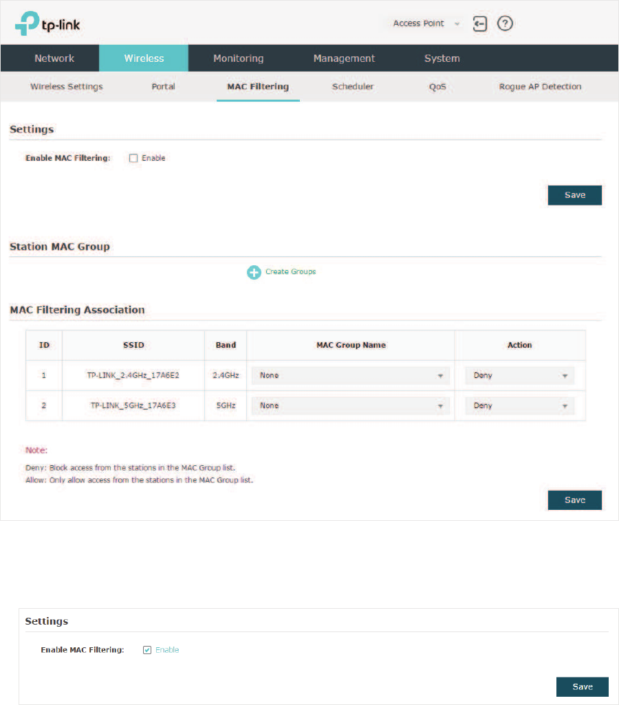
2.4 &RQILJXUH0$&)LOWHULQJ
MAC Filtering is used to allow or block the clients with specific MAC addresses to access
the network. With this feature you can effectively control clients’ access to the wireless
network according to your needs.
To configure MAC Filtering, go to the :LUHOHVV!0$&)LOWHULQJpage.
Follow the steps below to configure MAC Filtering on this page:
̝In the 6HWWLQJV section, check the box to enable0$&)LOWHULQJ, and click 6DYH.
38
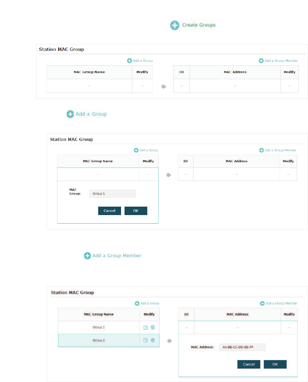
̝In the 6WDWLRQ0$&*URXS section, click and the following page will
appear.
̝Click and specify a name for the MAC group to be created. Click 2..
You can create up to eight MAC groups.
̝Select a MAC group in the group list (the color of the selected one will change to
blue). Click to add group members to the MAC group. Specify
the MAC address of the host and click 2.. In the same way, you can add more MAC
addresses to the selected MAC group.
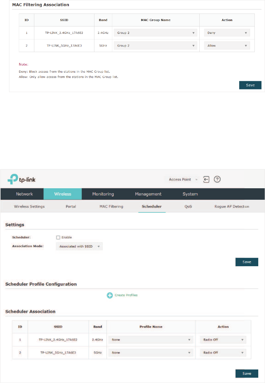
̝In the0$&)LOWHULQJ$VVRFLDWLRQsection, configure the filtering rule. For each SSID, you
can select a MAC group in the 0$&*URXS1DPH column and select the filtering rule
$OORZ'HQ\ in the$FWLRQ column. Click 6DYH.
39
For example, the following configuration means that the hosts in Group 2 are denied to
access the SSID73/,1.B*+]B$( on the 2.4GHz band and allowed to access
the SSID 73/,1.B*+]B$(on the 5GHz band.
2.5 &RQILJXUH6FKHGXOHU
With the Scheduler feature, the EAP or its wireless network can automatically turn on or
off at the time you set. For example, you can schedule the radio to operate only during the
office working time to reduce power consumption.
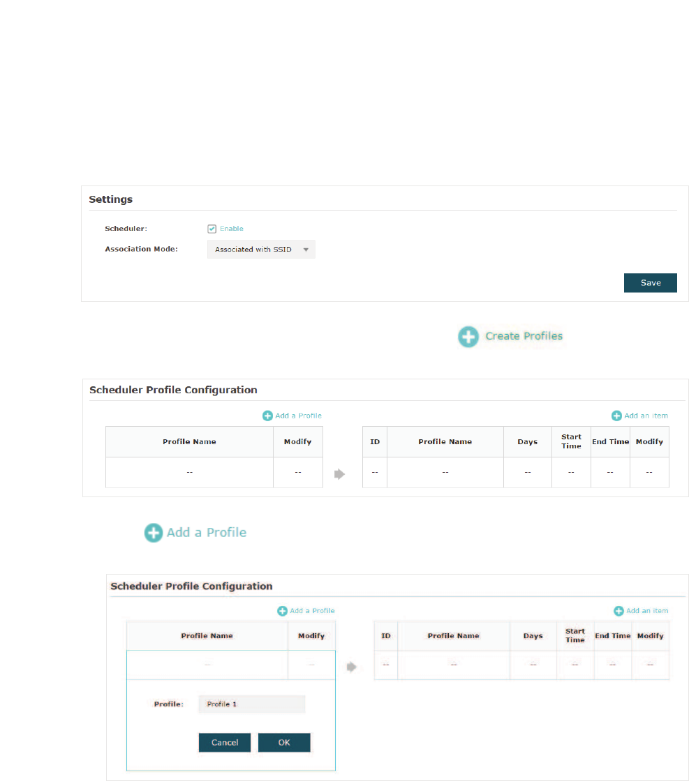
To configure Scheduler, go to the:LUHOHVV!6FKHGXOHU page.
40
Follow the steps below to configure Scheduler on this page:
̝In the 6HWWLQJV section, check the box to enable 6FKHGXOHU and select the $VVRFLDWLRQ
Mode. There are two modes: $VVRFLDWHGZLWK66,' (the scheduler profile will be applied
to the specific SSID) and $VVRFLDWHGZLWK$3(the profile will be applied to all SSIDs on
the EAP). Then click6DYH.
̝In the 6FKHGXOHU3URILOH&RQILJXUDWLRQsection, click and the following
page will appear.
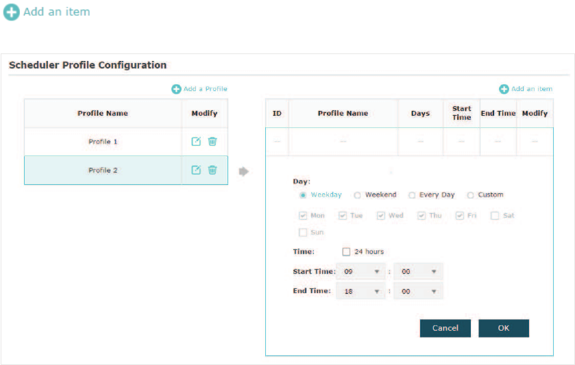
̝Click DQGVSHFLI\DQDPHIRUWKHSURƮOHWREHFUHDWHG&OLFN2.. You
FDQFUHDWHXSWRHLJKWSURƮOHV
41
̝Select a profile in the list (the color of the selected one will change to blue). Click
WRDGGWLPHUDQJHLWHPVWRWKHSURƮOH6SHFLI\WKH'D\6WDUW7LPHand
End Time of the time range, and click 2..
Tips:
You can add up to eight time range items for one profile. If there are several time range items in one
profile, the time range of this profile is the sum of all of these time ranges.
̝In the 6FKHGXOHU$VVRFLDWLRQ section, configure the scheduler rule. There are two
association modes:
Association with SSID
and
Association with AP
. The following
sections introduce how to configure each mode.
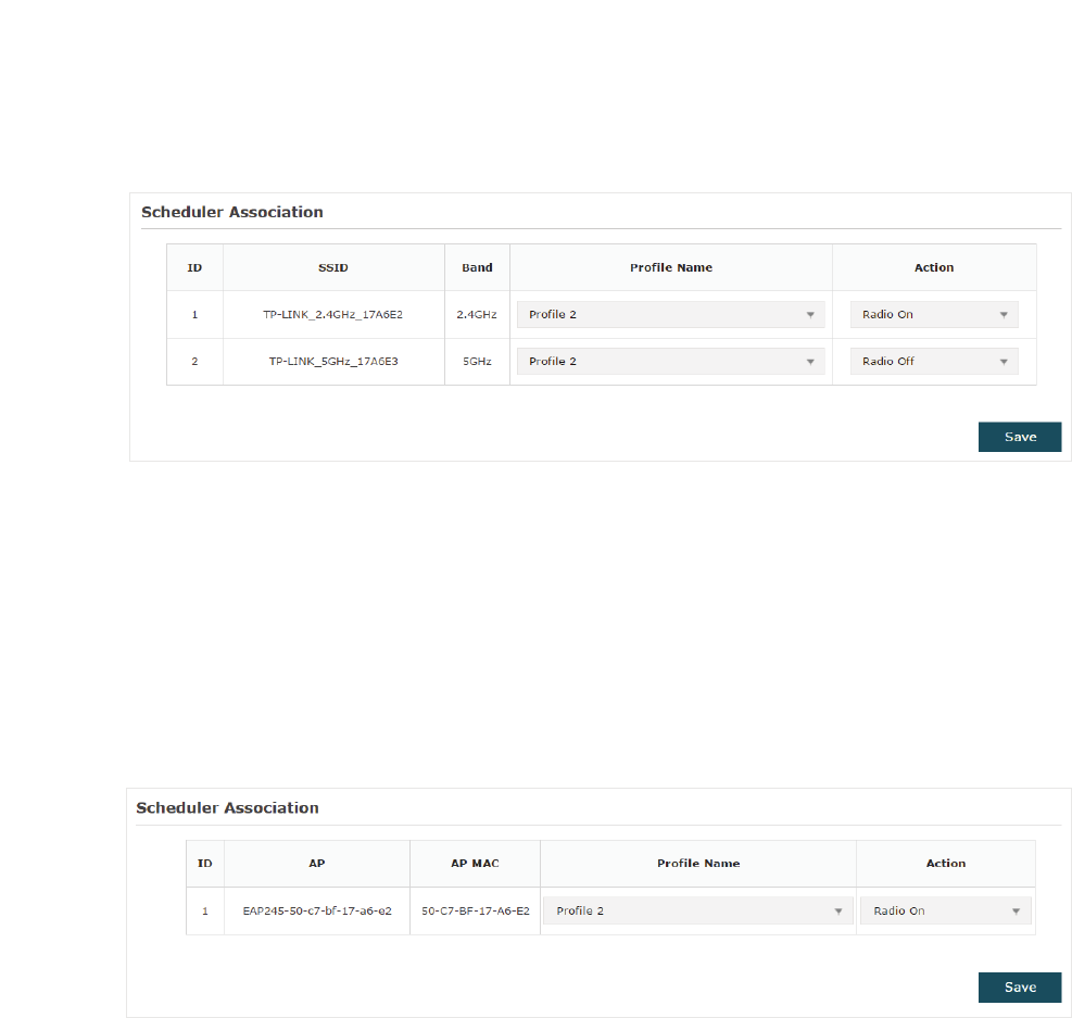
$VVRFLDWLRQZLWK66,'
If you select $VVRFLDWLRQZLWK66,' in step 1, the Scheduler Association table will
display all the SSIDs on the EAP. For each SSID, you can select a profile in the 3URILOH
1DPH column and select the scheduler rule 5DGLR2Q5DGLR2II in the$FWLRQ column.
Then click 6DYH.
42
For example, the following configuration means that during the time range defined
in Profile2, the radio of SSID TP-LINK_2.4GHZ_17A6E2 is on and the radio of SSID
TPLINK_5GHz_17A6E3 is off.
$VVRFLDWLRQZLWK$3
If you select $VVRFLDWLRQZLWK$3in step 1, the Scheduler Association table will display
the name and MAC address of the EAP. Select a profile in the3URILOH1DPHcolumn and
select the scheduler rule5DGLR2Q5DGLR2II in the $FWLRQ column. Then click6DYH.
For example, the following configuration means that during the time range defined in
Profile2, the radio of all SSIDs on the EAP is on.
2.6 &RQILJXUH4R6
Quality of service (QoS) is used to optimize the throughput and performance of the EAP
when handling differentiated wireless traffic, such as Voice-over-IP (VoIP), other types of
audio, video, streaming media, and traditional IP data.
In QoS configuration, you should set parameters on the transmission queues for
different types of wireless traffic and specify minimum and maximum wait time for data
transmission. In normal use, we recommend that you keep the default values.
43
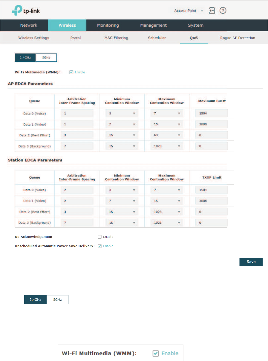
To configure QoS, go to the :LUHOHVV!4R6page.
Follow the steps below to configure QoS on this page:
̝Click to choose a frequency band to be configured.
̝Check the box to enable :L)L0XOWLPHGLD:00. With WMM enabled, the EAP uses
the QoS function to guarantee the high priority of the transmission of audio and video
packets.
Note:
If QRQO\mode is selected in 2.4GHz (or QRQO\DFRQO\or QDFPL[HG
mode selected in 5GHz), the WMM should be enabled. If WMM is disabled, the QRQO\mode
cannot be selected in 2.4GHz (or QRQO\DFRQO\ or QDFPL[HGmode in 5GHz).
44
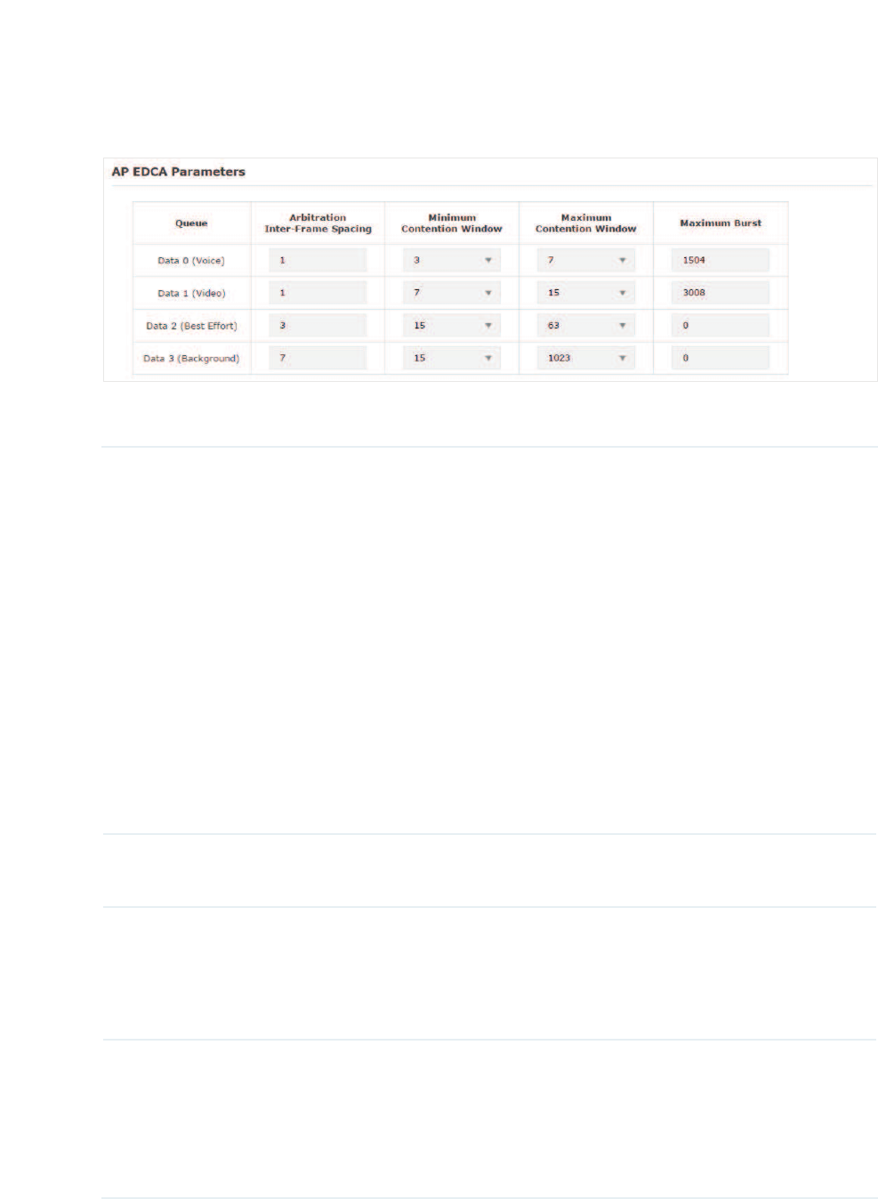
̝In the$3('&$3DUDPHWHUVsection, configure the AP EDCA ((Enhanced Distributed
Channel Access) parameters. AP EDCA parameters affect traffic flowing from the EAP
device to the client station. The following table detailedly explains these parameters.
The following table detailedly explains these parameters:
Queue Displays the transmission queue. By default, the priority from high to
low is Data 0, Data 1, Data 2, and Data 3. The priority may be changed if
you reset the EDCA parameters.
'DWD9RLFHHighest priority queue, minimum delay. Timesensitive
data such as VoIP and streaming media are automatically sent to this
queue.
'DWD9LGHR High priority queue, minimum delay. Time-sensitive
video data is automatically sent to this queue.
'DWD%HVW(IIRUW Medium priority queue, medium throughput and
delay. Most traditional IP data is sent to this queue.
'DWD%DFNJURXQGLowest priority queue, high throughput. Bulk data
that requires maximum throughput and is not time-sensitive is sent to
this queue (FTP data, for example).
Arbitration Inter-
Frame Space
A wait time for data frames. The wait time is measured in slots. Valid
values are from 0 to 15.
Minimum
Contention
Window
A list to the algorithm that determines the initial random backoff wait
time (window) for retry of a transmission.
This value cannot be higher than the value of Maximum Contention
Window.
Maximum
Contention
Window
The upper limit (in milliseconds) for the doubling of the random backoff
value. This doubling continues until either the data frame is sent or the
Maximum Contention Window size is reached.
This value must be higher than the value of Minimum Contention
Window.
45
Maximum Burst Maximum Burst specifies the maximum burst length allowed for
packet bursts on the wireless network. A packet burst is a collection of
multiple frames transmitted without header information. The decreased
overhead results in higher throughput and better performance.
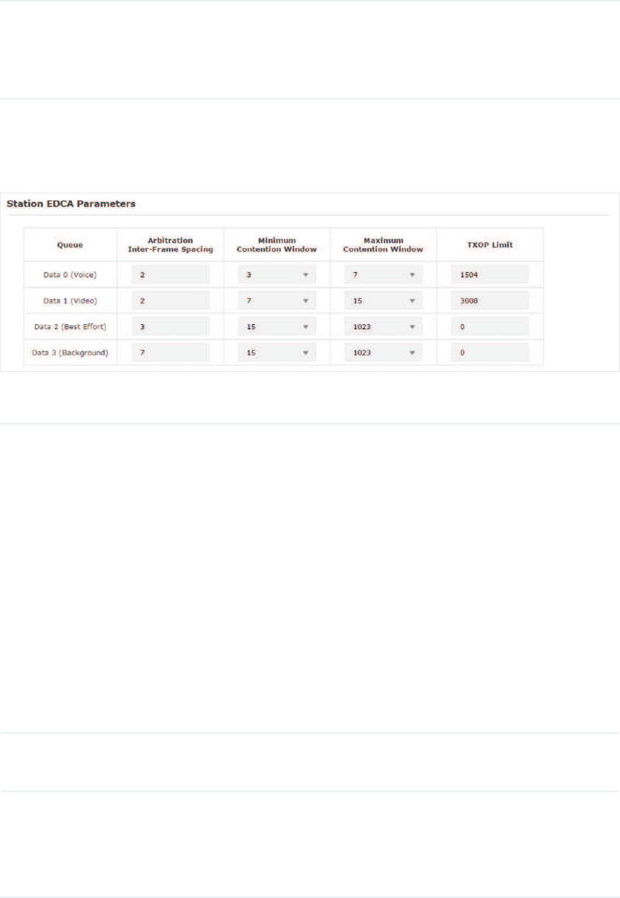
̝In the6WDWLRQ('&$3DUDPHWHUV section, configure the station EDCA (Enhanced
Distributed Channel Access) parameters. Station EDCA parameters affect traffic
flowing from the client station to the EAP device.
The following table detailedly explains these parameters:
Queue Displays the transmission queue. By default, the priority from high to
low is Data 0, Data 1, Data 2, and Data 3. The priority may be changed if
you reset the EDCA parameters.
'DWD9RLFHHighest priority queue, minimum delay. Timesensitive
data such as VoIP and streaming media are automatically sent to this
queue.
'DWD9LGHR High priority queue, minimum delay. Time-sensitive
video data is automatically sent to this queue.
'DWD%HVW(IIRUW Medium priority queue, medium throughput and
delay. Most traditional IP data is sent to this queue.
'DWD%DFNJURXQGLowest priority queue, high throughput. Bulk data
that requires maximum throughput and is not time-sensitive is sent to
this queue (FTP data, for example).
Arbitration Inter-
Frame Space
A wait time for data frames. The wait time is measured in slots. Valid
values are from 0 to 15.
Minimum
Contention
Window
A list to the algorithm that determines the initial random backoff wait
time (window) for retry of a transmission.
This value cannot be higher than the value of Maximum Contention
Window.
46
Maximum
Contention
Window
The upper limit (in milliseconds) for the doubling of the random backoff
value. This doubling continues until either the data frame is sent or the
Maximum Contention Window size is reached.
This value must be higher than the value of Minimum Contention
Window.
TXOP Limit The TXOP Limit is a station EDCA parameter and only applies to traffic
flowing from the client station to the EAP device.
The Transmission Opportunity (TXOP) is an interval of time, in
milliseconds, when a WME (Wireless Multimedia Extensions) client
station has the right to initiate transmissions onto the wireless medium
(WM) towards the EAP device. The valid values are multiples of 32
between 0 and 8192.
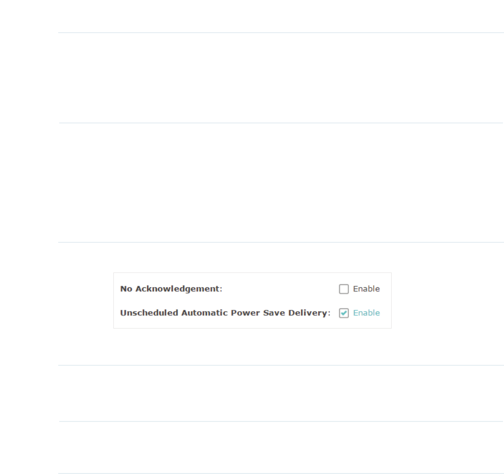
̝Choose whether to enable the following two options according to your need.
The following table detailedly explains these options:
No Acknowledgement With this option enabled, the EAP would not acknowledge frames
with QosNoAck. No Acknowledgement is recommended if VoIP
phones access the network through the EAP device.
Unscheduled
Automatic Power Save
Delivery
As a power management method, it can greatly improve the
energy-saving capacity of clients.
̝Click 6DYH.
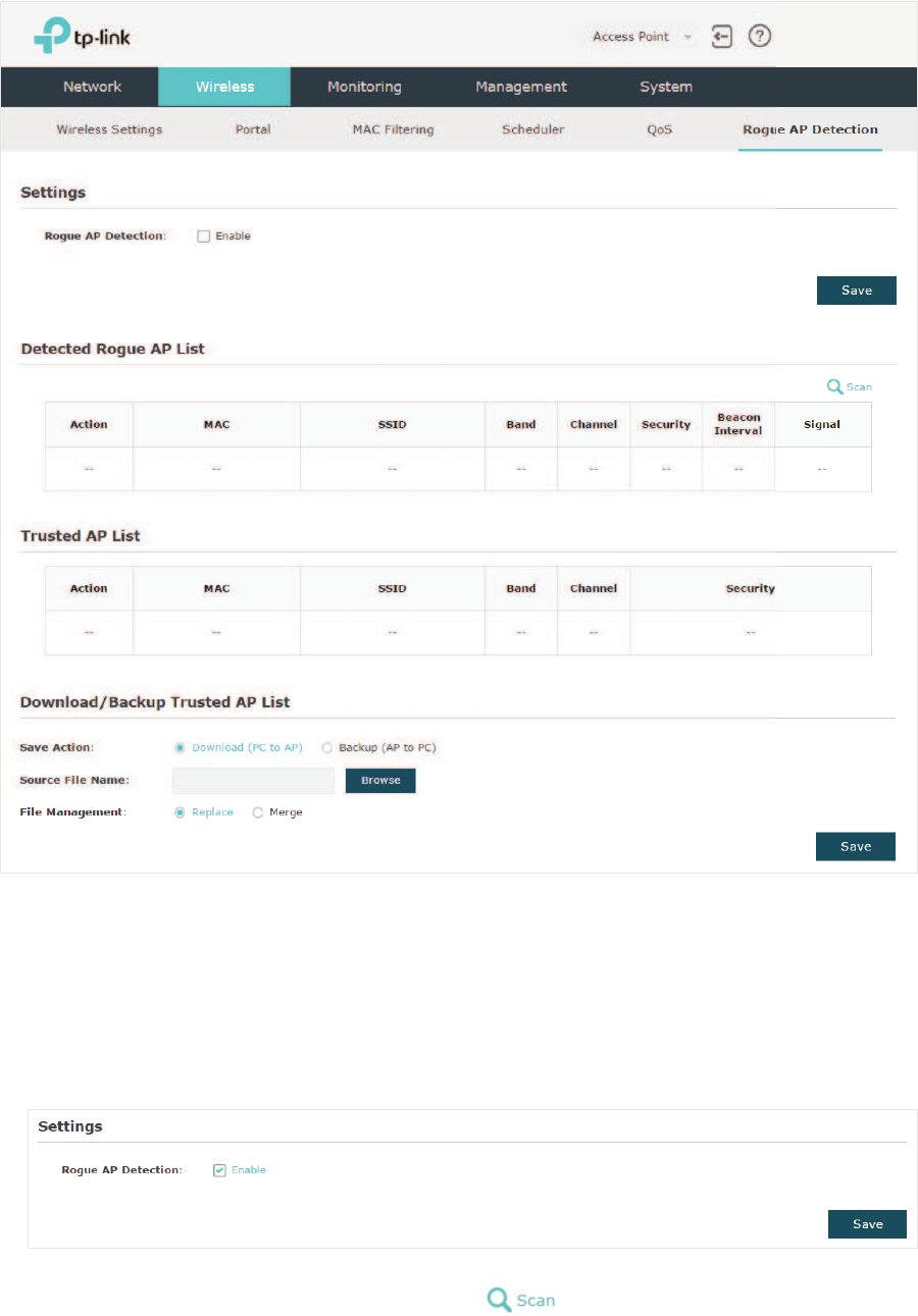
2.7 &RQILJXUH5RJXH$3'HWHFWLRQ
A Rogue AP is an access point that is installed on a secure network without explicit
authorization from the network administrator. With Rogue AP Detection, the EAP can scan
all channels to detect the nearby APs and display the detected APs in the Detected Rogue
AP list. If the specific AP is known as safe, you can move it to the Trusted APs list. Also, you
can backup and import the Trusted AP list as needed.
Note:
The Rogue AP Detection feature is only used for collecting information of the nearby wireless
network and does not impact the detected APs, no matter what operations you have executed in
this feature.
47
To configure Rogue AP Detection, go to the :LUHOHVV!5RJXH$3'HWHFWLRQ page.
'HWHFW5RJXH$3V0RYHWKH5RJXH$3VWRWKH7UXVWHG$3/LVW
Follow the steps below to detect the nearby APs and move the trusted ones to the Trusted
AP list.
̝In the 6HWWLQJVsection, check the box to enable 5RJXH$3'HWHFWLRQ. Click 6DYH.
̝In the 'HWHFWHG5RJXH$3/LVW section, click .
48
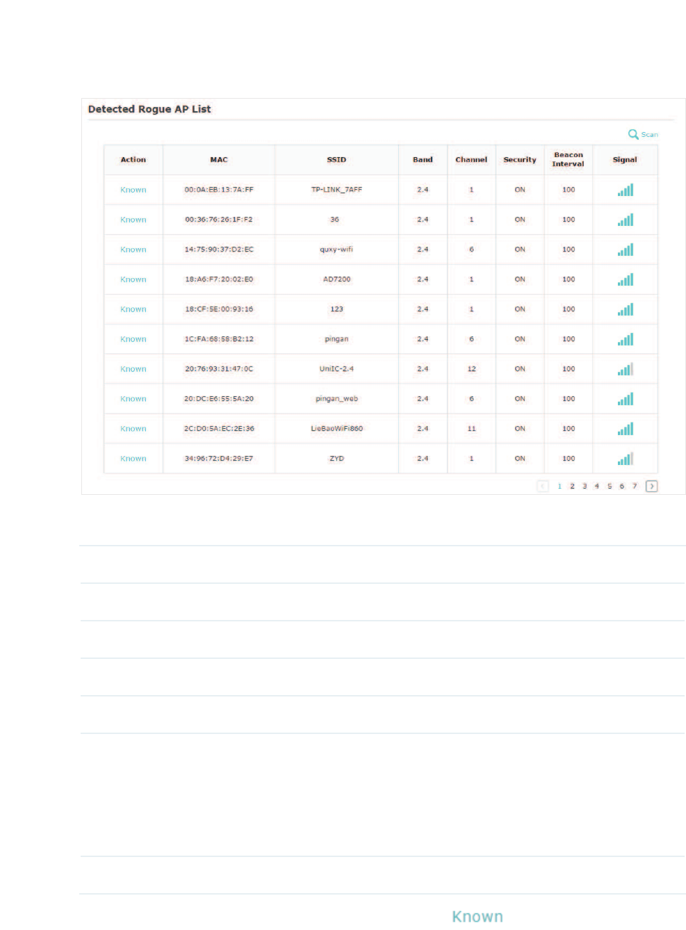
̝Wait for a few seconds without any operation. After detection is finished, the detected
APs will be displayed in the list.
The following table introduces the displayed information of the APs:
MAC Displays the MAC address of the AP.
SSID Displays the SSID of the AP.
Band Displays the frequency band the AP is working on.
Channel Displays the channel the AP is using.
Security Displays whether the security mode is enabled on the AP.
Beacon Interval Displays the Beacon Interval value of the EAP.
Beacon frames are sent periodically by the AP to announce to
the stations the presence of a wireless network. Beacon Interval
determines the time interval of the beacon frames sent by the AP
device.
Signal Displays the signal strength of the AP.
̝To move the specific AP to the Trusted AP list, click in the $FWLRQ column. For
example, we move the first two APs in the above Detected Rogue AP list to the Trusted
AP list.
49
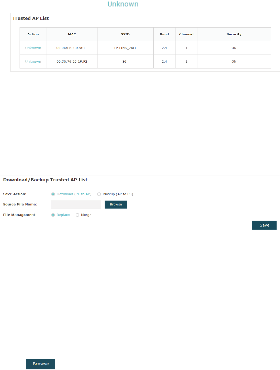
̝View the trusted APs in the7UXVWHG$3/LVW section. To move the specific AP back to
the Rogue AP list, you can click in the $FWLRQ column.
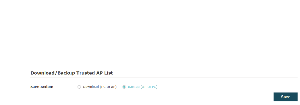
0DQDJHWKH7UXVWHG$3/LVW
You can download the trusted AP list from your local host to the EAP or backup the current
Trusted AP list to your local host.
̝
g'RZQORDGWKH7UXVWHG$3/LVW)URPWKH+RVW
You can import a trusted AP list which records the MAC addresses of the trusted APs. The
AP whose MAC address is in the list will not be detected as a rogue AP.
Follow the steps below to import a trusted AP list to the EAP:
̝Acquire the trusted AP list. There are two ways:
• Backup the list from a EAP. For details, refer to
Backup the Trusted AP List to the
Host
.
• Manually create a trusted AP list. Create a txt. file, input the MAC addresses of the
trusted APs in the format XX:XX:XX:XX:XX:XX and use the Space key to separate each
MAC address. Save the file as a FIJfile.
̝On this page, check the box to choose 'RZQORDG3&WR$3.
̝Click and select the trusted AP list from your local host.
̝Select the file management mode. Two modes are available: 5HSODFH and 0HUJH.
Replace means that the current trusted AP list will be replaced by the one you import.
Merge means that the APs in the imported list will be added to the current list with the
original APs remained.
50
̝Click 6DYH to import the trusted AP list.
̝
g%DFNXSWKH7UXVWHG$3/LVWWRWKH+RVW
You can backup the current trusted AP list and save the backup file to the local host.
Follow the steps below to backup the current trusted AP list:
̝On this page, check the box to choose %DFNXS$3WR3&.
̝Click6DYHand the current trusted AP list will be downloaded to your local host as a FIJ
file.

51
3 0RQLWRUWKH1HWZRUN
This chapter introduces how to monitor the running status and statistics of the wireless
network, including:
̝
gMonitor the EAP
̝
gMonitor the SSIDs
̝
gMonitor the Clients
52
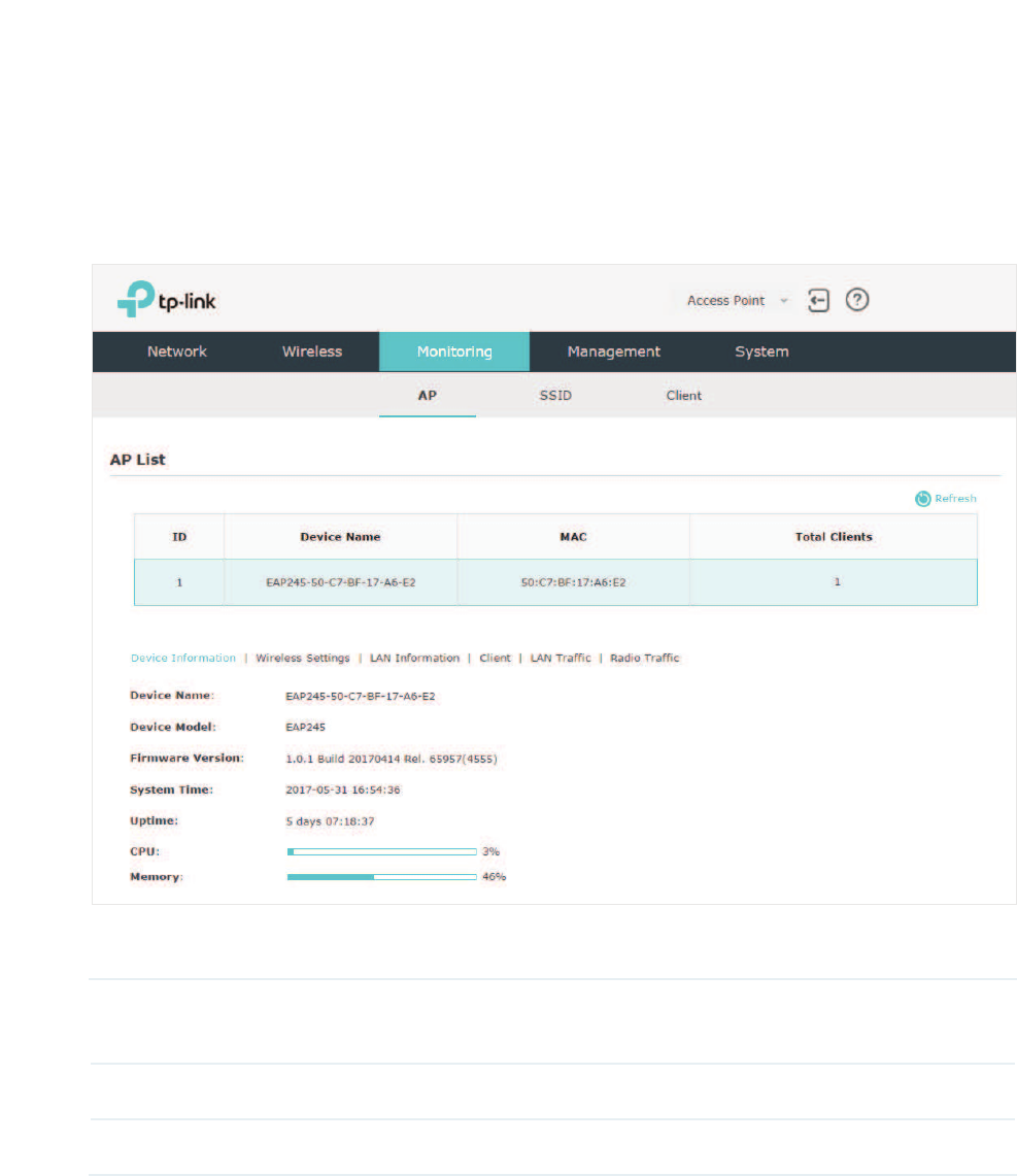
3.1 0RQLWRUWKH($3
You can view the information of the EAP, including device information, wireless settings,
LAN information, client information, LAN traffic and radio traffic.
To monitor the EAP information, go to the 0RQLWRULQJ!$3 page.
The AP List displays the following information:
Device Name Displays the name of the EAP. The name consists of the product model
followed with the MAC address of the EAP.
MAC Displays the MAC address of the EAP.
Total Clients Displays the number of clients currently connected to the EAP.
53
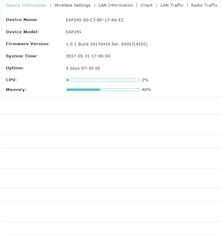
9LHZ'HYLFH,QIRUPDWLRQ
Under this tab, you can view the device information of EAP.
The following device information is displayed:
Device Name Displays the name of the EAP. The name consists of the product model
followed with the MAC address of the EAP.
Device Model Displays the product model of the EAP.
Firmware
Version
Displays the current firmware version the EAP. To update the firmware, you
can refer to
Update the Firmware
.
System Time Displays the current system time. To configure the system time, you can
refer to
Configure the System Time
.
Uptime Displays how long the EAP has been working since it starts up.
CPU Displays the CPU occupancy. If this value is too high, the EAP may work
abnormally.
Memory Displays the memory occupancy.
54
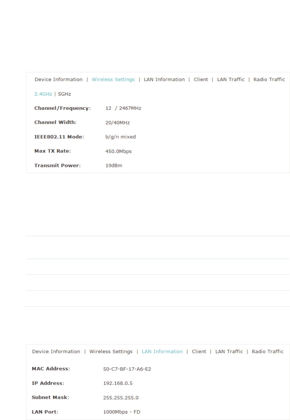
9LHZ:LUHOHVV6HWWLQJV
Under this tab, you can view the wireless settings of EAP.
Tips:
To change the wirless settings, you can refer to
Configure the Wireless Parameters
.
Note:
g For a dual-band EAP, there are two bands: 2.4GHz and 5GHz. You can click to select a band to
view.
g The following figure posted in the introduction takes 2.4GHz as an example.
The following wireless information is displayed:
Channel/
Frequency
Displays the channel and frequency which are currently used by the EAP.
Channel Width Displays the channel width which is currently used by the EAP.
IEEE802.11 Mode Displays the IEEE802.11 protocol currently used by the EAP.
Max TX Rate Displays the maximum physical rate of the EAP.
9LHZ/$1,QIRUPDWLRQ
Under this tab, you can view the LAN information of EAP.
55
The following LAN information is displayed:
MAC Address Displays the MAC address of the EAP.
IP Address Displays the IP address of the EAP.
Subset Mask Displays the subnet mask of the EAP.
LAN Port Displays the maximum physical transmission rate and duplex mode of the
port. HD meas half-duplex and FD means full-duplex.
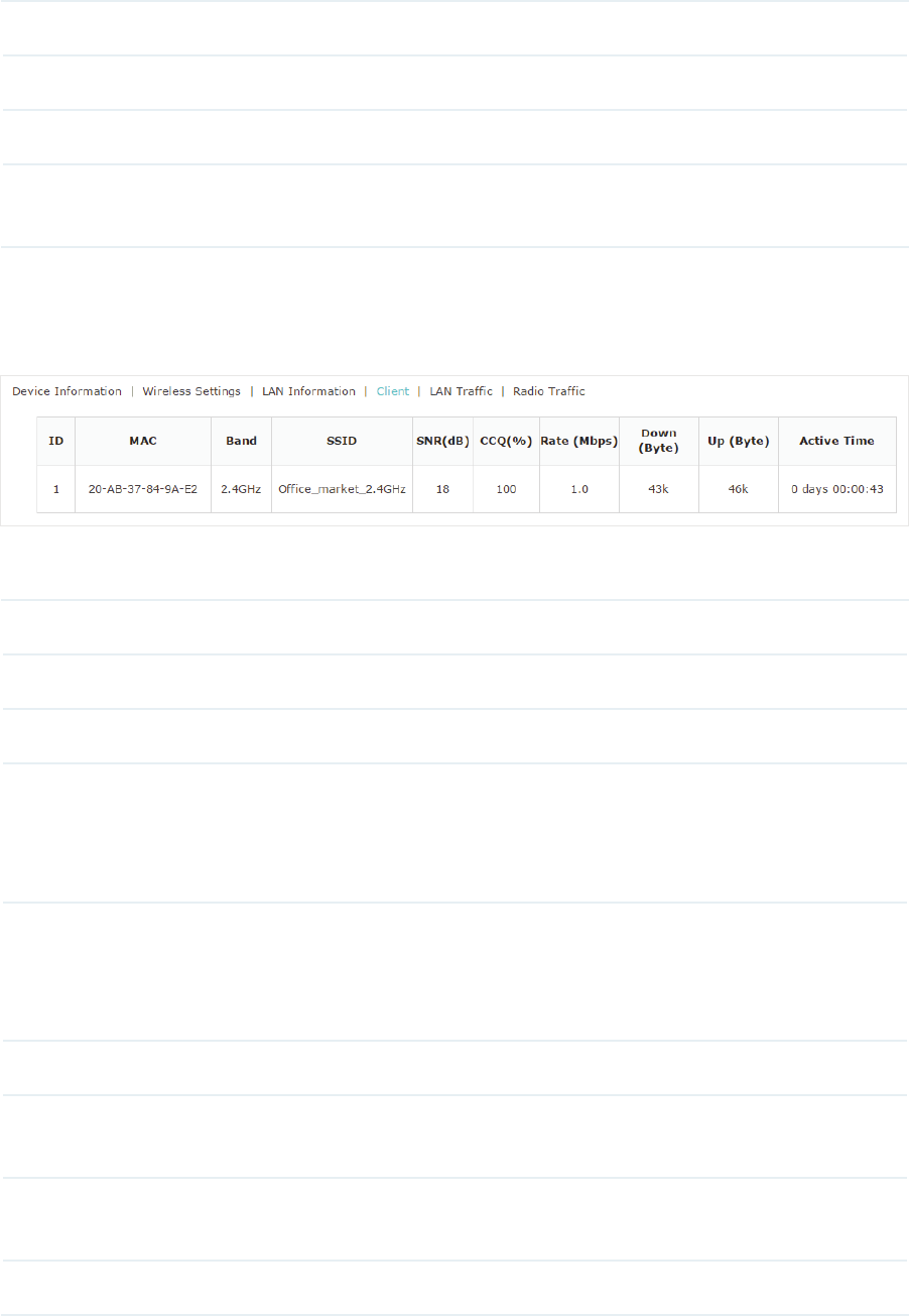
9LHZ&OLHQW,QIRUPDWLRQ
Under this tab, you can view the client information of EAP.
The following client information is displayed:
MAC Displays the MAC address of the client.
Band Displays the frequency band the client is working on.
SSID Displays the SSID the client is connected to.
SNR (dB) Displays the Signal to Noise Ratio (SNR) of the client. SNR refers to
the power ratio between the received wireless signal strength and the
environmental noise strength. The bigger SNR value is, the better network
performance the device can provide.
CCQ (%) Displays the wireless Client Connection Quality (CCQ). CCQ refers to
the ratio between the current effective transmission bandwidth and the
theoretical maximum available bandwidth. CCQ reflects the quality of the
actual link. A bigger value means a better utilization of the bandwidth.
Rate (Mbps) Displays the wireless transmission rate of the client.
Down (Byte) Displays the client’s total downloaded traffic from the EAP since the last
connection.
Up (Byte) Displays the client’s total uploaded traffic to the EAP since the last
connection.
Active Time Displays how long the client has been connected to the EAP.
56
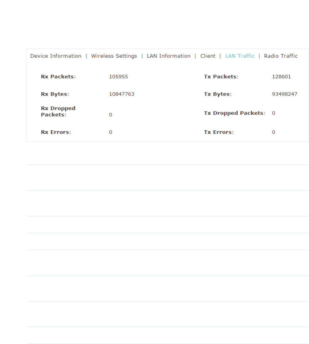
9LHZ/$17UDIILF
Under this tab, you can view the LAN traffic of EAP.
The following traffic information of the LAN is displayed:
Rx Packets Displays the total number of received packets in the LAN since the EAP
starts up.
Tx Packets Displays the total number of sent packets in the LAN since the EAP starts
up.
Rx Bytes Displays the total received traffic in the LAN since the EAP starts up.
Tx Bytes Displays the total sent traffic in the LAN since the EAP starts up.
Rx Dropped
Packets
Displays the total number of the dropped packets which are received by the
EAP since it starts up.
Tx Dropped
Packets
Displays the total number of the dropped packets which are sent by the
EAP since it starts up.
Rx Errors Displays the total number of the received error packets since the EAP
starts up.
Tx Errors Displays the total number of the sent error packets since the EAP starts up.
57
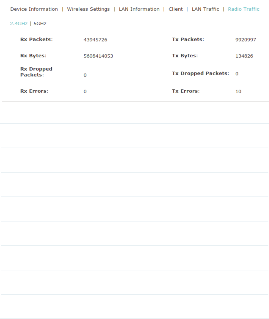
9LHZ5DGLR7UDIILF
Under this tab, you can view the radio traffic of EAP.
The following traffic information of the radio is displayed:
Rx Packets Displays the total number of the received packets on the 2.4GHz/5GHz
band since the EAP starts up.
Tx Packets Displays the total number of the sent packets on the 2.4GHz/5GHz band
since the EAP starts up.
Rx Bytes Displays the total received traffic on the 2.4GHz/5GHz band since the EAP
starts up.
Tx Bytes Displays the total sent traffic on the 2.4GHz/5GHz band since the EAP starts
up.
Rx Dropped
Packets
Displays the total number of the dropped packets which are received on
the 2.4GHz/5GHz band since the EAP starts up.
Tx Dropped
Packets
Displays the total number of the dropped packets which are sent on the
2.4GHz/5GHz band since the EAP starts up.
Rx Errors Displays the total number of error packets which are received on the
2.4GHz/5GHz band since the EAP starts up.
Tx Errors Displays the total number of error packets which are sent on the
2.4GHz/5GHz band since the EAP starts up.
58
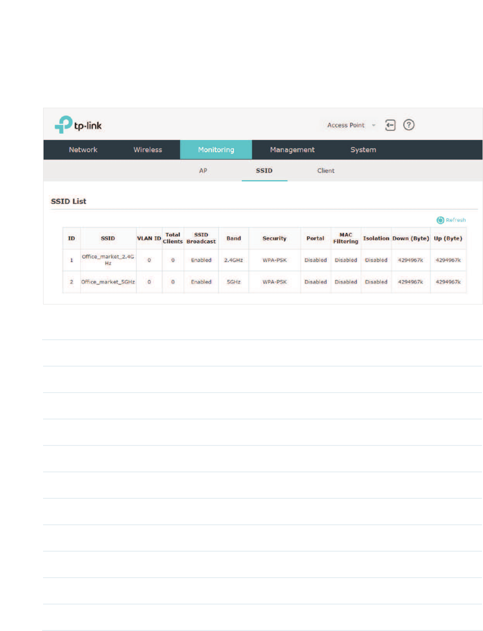
3.2 Monitor the SSIDs
You can monitor the SSID information of the EAP.
To monitor the SSID information, go to the 0RQLWRULQJ!66,' page.
The following table introduces the displayed information of the SSID:
SSID Displays the SSID name.
VLAN ID Displays the VLAN ID of the SSID.
Total Clients Displays the number of clients currently connected to the SSID.
SSID Broadcast Displays whether the SSID broadcast is enabled.
Band Displays the frequency band the SSID is currently using.
Security Displays the security mode of the SSID.
Portal Displays whether portal authentication is enabled on the SSID.
MAC Filtering Displays whether MAC filtering is enabled on the SSID.
Isolation Displays whether SSID isolation is enabled on the SSID.
Down (Byte) Displays the total download traffic since the SSID starts working.
Up (Byte) Displays the total upload traffic since the SSID starts working.
59
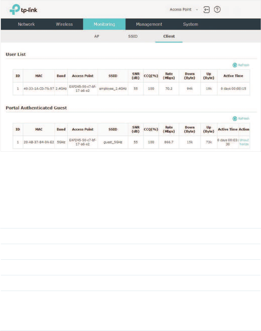
3.3 Monitor the Clients
You can monitor the information of the clients connected to the EAP.
To monitor the client information, go to the0RQLWRULQJ!&OLHQW page.
There are two types of clients: users and portal authenticated guests. Users are the clients
that connect to the SSID with portal authentication disabled. Guests are the clients that
connect to the SSID with portal authentication enabled.
9LHZWKH8VHUV
The following table introduces the displayed information of the users.
MAC Displays the MAC address of the user.
Band Displays the frequency band the user is working on.
Access Point Displays the device name of the EAP the user is connected to.
SSID Displays the SSID the user is connected to.
SNR (dB) Displays the Signal to Noise Ratio (SNR) of the user. SNR refers to the power
ratio between the received wireless signal strength and the environmental
noise strength. The bigger SNR value is, the better network performance
the device can provide.

60
CCQ (%) Displays the wireless Client Connection Quality (CCQ) of the user. CCQ
refers to the ratio between the current effective transmission bandwidth
and the theoretical maximum available bandwidth. CCQ reflects the quality
of the actual link. A bigger value means a better utilization of the bandwidth.
Rate (Mbps) Displays the wireless transmission rate of the user.
Down (Byte) Displays the user’s total downloaded traffic from the EAP since the last
connection.
Up (Byte) Displays the user’s total uploaded traffic to the EAP since the last
connection.
Active Time Displays how long the user has been connected to the EAP.
9LHZDQG0DQDJHWKH3RUWDO$XWKHQWLFDWHG*XHVWV
The following table introduces the displayed information of the portal authentication
guests.
MAC Displays the MAC address of the user.
Band Displays the frequency band the user is working on.
Access Point Displays the device name of the EAP the user is connected to.
SSID Displays the SSID the user is connected to.
SNR (dB) Displays the Signal to Noise Ratio (SNR) of the user. SNR refers to the power
ratio between the received wireless signal strength and the environmental
noise strength. The bigger SNR value is, the better network performance
the device can provide.
CCQ (%) Displays the wireless Client Connection Quality (CCQ) of the user. CCQ
refers to the ratio between the current effective transmission bandwidth
and the theoretical maximum available bandwidth. CCQ reflects the quality
of the actual link. A bigger value means a better utilization of the bandwidth.
Rate (Mbps) Displays the wireless transmission rate of the user.
Down (Byte) Displays the user’s total downloaded traffic from the EAP since the last
connection.
Up (Byte) Displays the user’s total uploaded traffic to the EAP since the last
connection.
Active Time Displays how long the user has been connected to the EAP.
In the $FWLRQ column, you can click 8QDXWKRUL]Hto delete the authentication information of
the guest. To access the internet, the guest needs to log in again.

61
4 0DQDJHWKH($3
The EAP provides powerful functions of device management and maintenance. This
chapter introduces how to manage the EAP, including:
̝
gManage System Logs
̝
gConfigure Web Server
̝
gConfigure Management Access
̝
gConfigure Trunk (For EAP330)
̝
gConfigure LED
̝
gConfigure Wi-Fi Control (For EAP115-Wall)
̝
gConfigure SSH
̝
gConfigure Management VLAN
̝
gConfigure SNMP
62
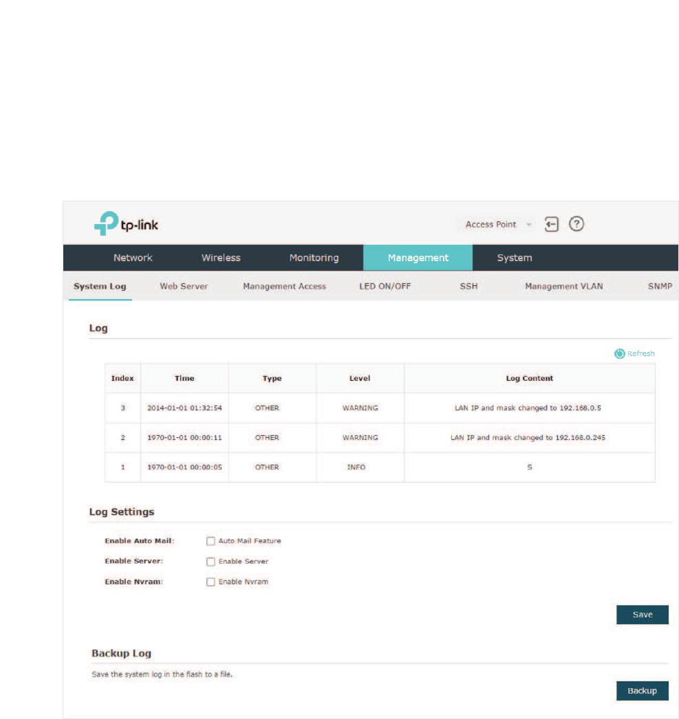
4.1 0DQDJH6\VWHP/RJV
System logs record information about hardware, software as well as system issues and
monitors system events. With the help of system log, you can get informed of system
running status and detect the reasons for failure.
To manage system logs, go to the 0DQDJHPHQW!6\VWHP/RJpage.
On this page, you can view the system logs and configure the way of receiving system
logs. For EAP320/EAP330/EAP225, you can also backup the system logs to your local
host.
63
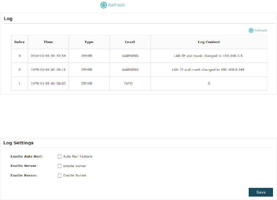
9LHZ6\VWHP/RJV
In the /RJ section, you can click to refresh the logs and view them in the table.
&RQILJXUHWKH:D\RI5HFHLYLQJ/RJV
In the/RJ6HWWLQJV section, you can configure the ways of receiving system logs.
Follow the steps below to configure this feature:
̝Check the corresponding box to enable one or more ways of receiving system logs,
and configure the related parameters. Three ways are available:
Auto Mail
Server
and
Nvram
.
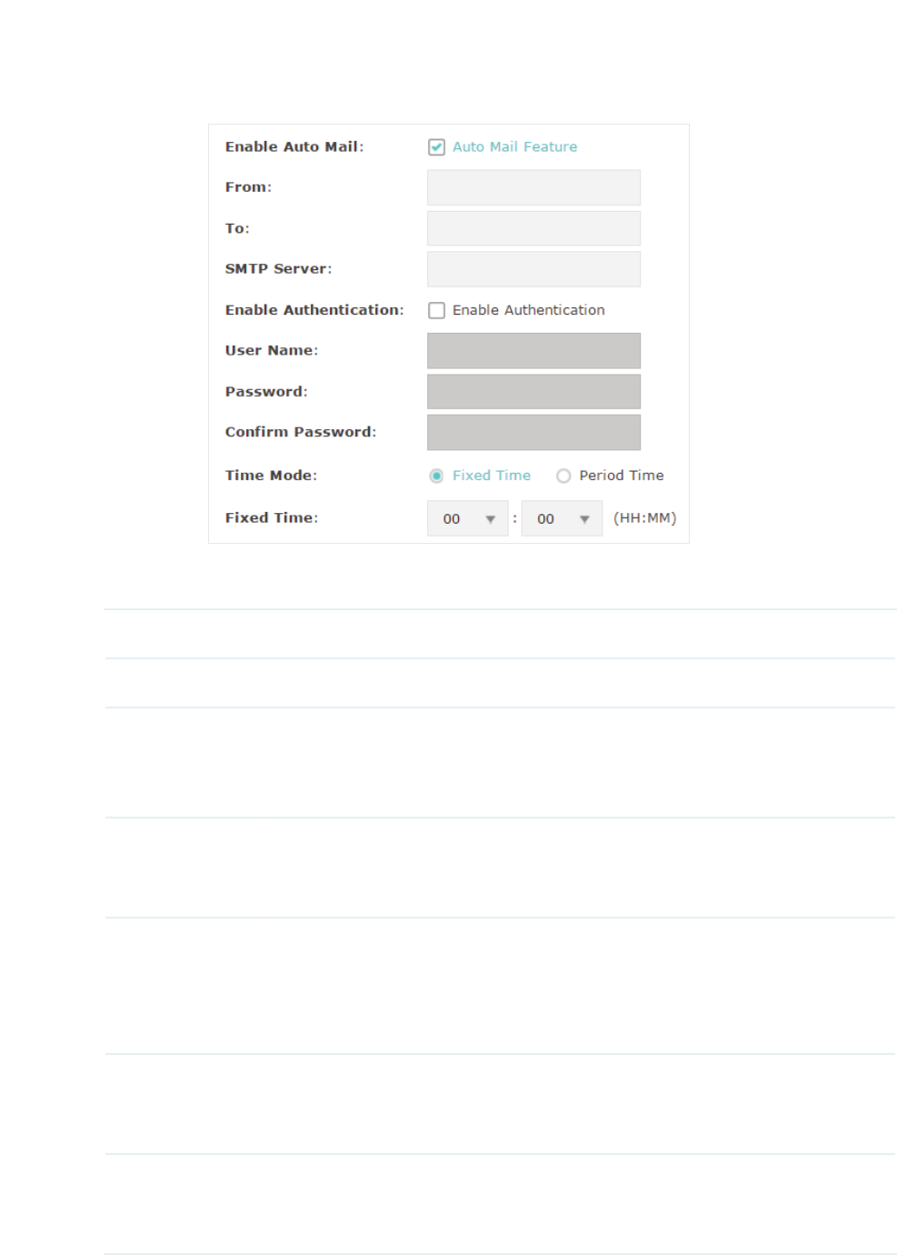
$XWR0DLO
If Auto Mail is configured, system logs will be sent to a specified mailbox. Check the box
to enable the feature and configure the related parameters.
64
Note:
SSL encryption is not currently supported.
The following table introduces how to configure these parameters:
From Enter the sender’s E-mail address.
To Enter the receiver’s E-mail address.
SMTP Server Enter the IP address of the sender’s SMTP server.
1RWH
At present, the domain name of SMTP server is not supported in
this field.
Enable
Authentication
If the sender’s mailbox is configured with You can check the box to
enable mail server authentication. Enter the sender’s username and
password.
Time Mode Select Time Mode: )L[HG7LPHor 3HULRG7LPH.
Fixed Time means that the system logs will be sent at the specific time
every day. Period Time means that the system logs will be sent at the
specific time interval.
Fixed Time If you select )L[HG7LPH, specify a fixed time to send the system log
mails. For example, 08:30 indicates that the mail will be sent at 8:30 am
everyday.
Period Time If you select 3HULRG7LPH, specify a period time to regularly send the
system log mail. For example, 6 indicates that the mail will be sent every
six hours.
65
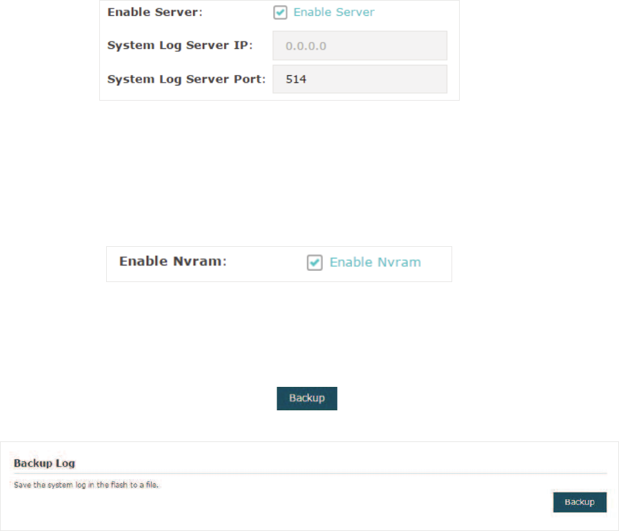
Server
If Server is configured, system logs will be sent to the specified system log server, and
you can use the syslog software to view the logs on the server.
Enable this feature and enter the IP address and port of the system log server.
1YUDP
Nvram (Non-volatile Random Access Memory) is a RAM that can still save data even if
a device is power off. With this option enabled, the Nvram feature can help reserve the
system logs when the EAP is power off.
̝Click 6DYH.
%DFNXS/RJV)RU($3($3($3
In the Backup Log section, you can click to backup the current system logs into a
file and save the file on your local host.
4.2 &RQILJXUH:HE6HUYHU
With the web server, you can log in to the management web page of the EAP. You can
configure the web server parameters of the EAP according to your needs.
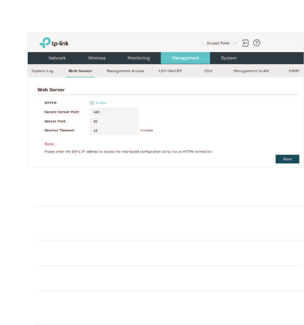
66
To configure Web Server, go to the 0DQDJHPHQW!:HE6HUYHU page.
Follow the steps below to configure Web Server:
̝Refer to the following table to configure the parameters:
HTTPS HTTPS (Hypertext Transfer Protocol Secure) function is based on the
SSL or TLS protocol. It provides a secure connection between the
client and the EAP. HTTPS is enabled by default.
Secure Server Port Designate a secure server port for web server in HTTPS mode. By
default the port is 443.
Server Port Designate a server port for web server in HTTP mode. By default the
port is 80.
Session Timeout Set the session timeout. If you do nothing with the web page within
the timeout, the system will log out automatically. You can log in again
if you want to go back to web page.
̝Click6DYH.
4.3 &RQILJXUH0DQDJHPHQW$FFHVV
By default, all hosts in the LAN can log in to the management web page of the EAP with the
correct username and password. To control the hosts’ access to the web page of the EAP,
you can specify the MAC addresses of the hosts that are allowed to access the web page,
and other hosts without MAC addresses specified are not allowed to access the web page.
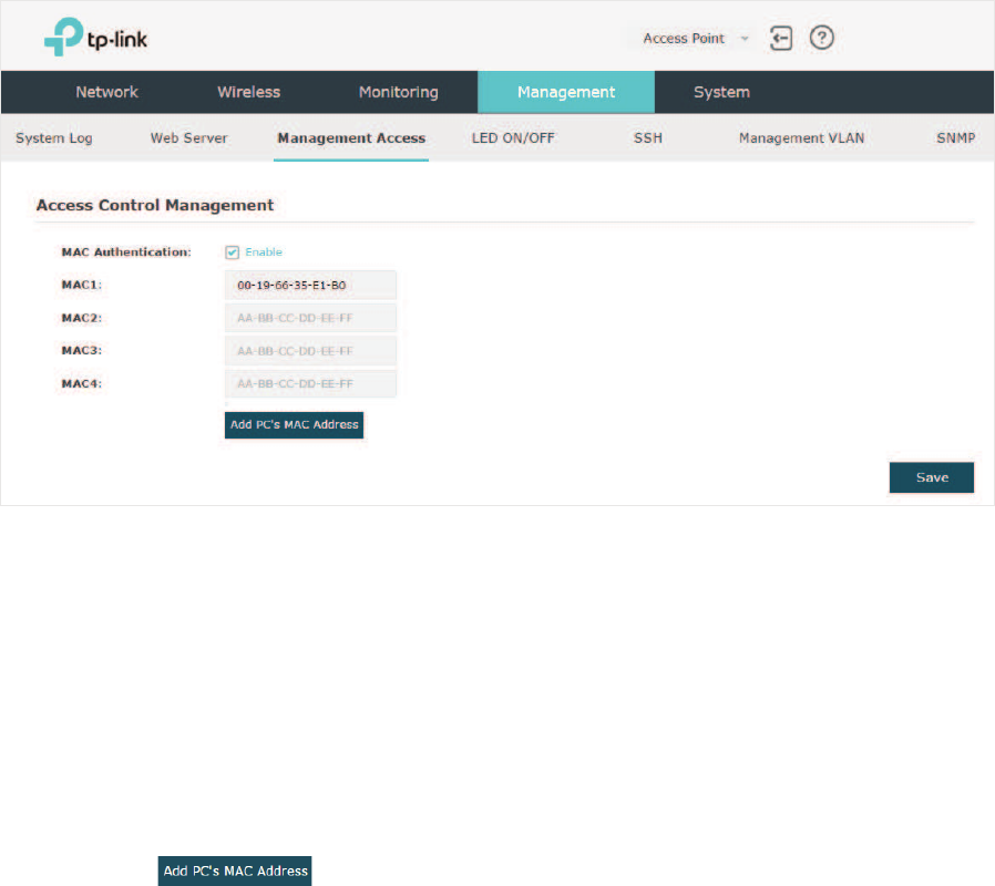
67
To configure Management Access, go to the 0DQDJHPHQW!0DQDJHPHQW$FFHVV page.
Follow the steps below to configure Management Access on this page:
̝Check the box to enable0$&$XWKHQWLFDWLRQ.
̝Specify one or more MAC addresses in the 0$&0$&0$&0$& fields. Up to
four MAC addresses can be added.
̝Click 6DYH.
Tips:
g You can click to quickly add the MAC address of your current logged-in host, .
g Verify the MAC addresses carefully. Once the settings are saved, only the hosts in the MAC
address list can access the web page of the EAP.
g If you cannot log in to the web page after saving the wrong configuration, you can reset the EAP
to the factory defaults and use the default username and password (both admin) to log in.
4.4 &RQILJXUH7UXQN)RU($3
The trunk function can bundle multiple Ethernet links into a logical link to increase
bandwidth and improve network reliability. The EAP330 has two 1000Mbps Ethernet ports.
If the Trunk function is enabled and the ports are in the speed of 1000Mbps Full Duplex,
the whole bandwidth of the trunk link is up to 4Gbps (2000Mbps * 2).
Note:
The trunk feature here refers to static trunk. Make sure that the trunk mode of the peer is static.
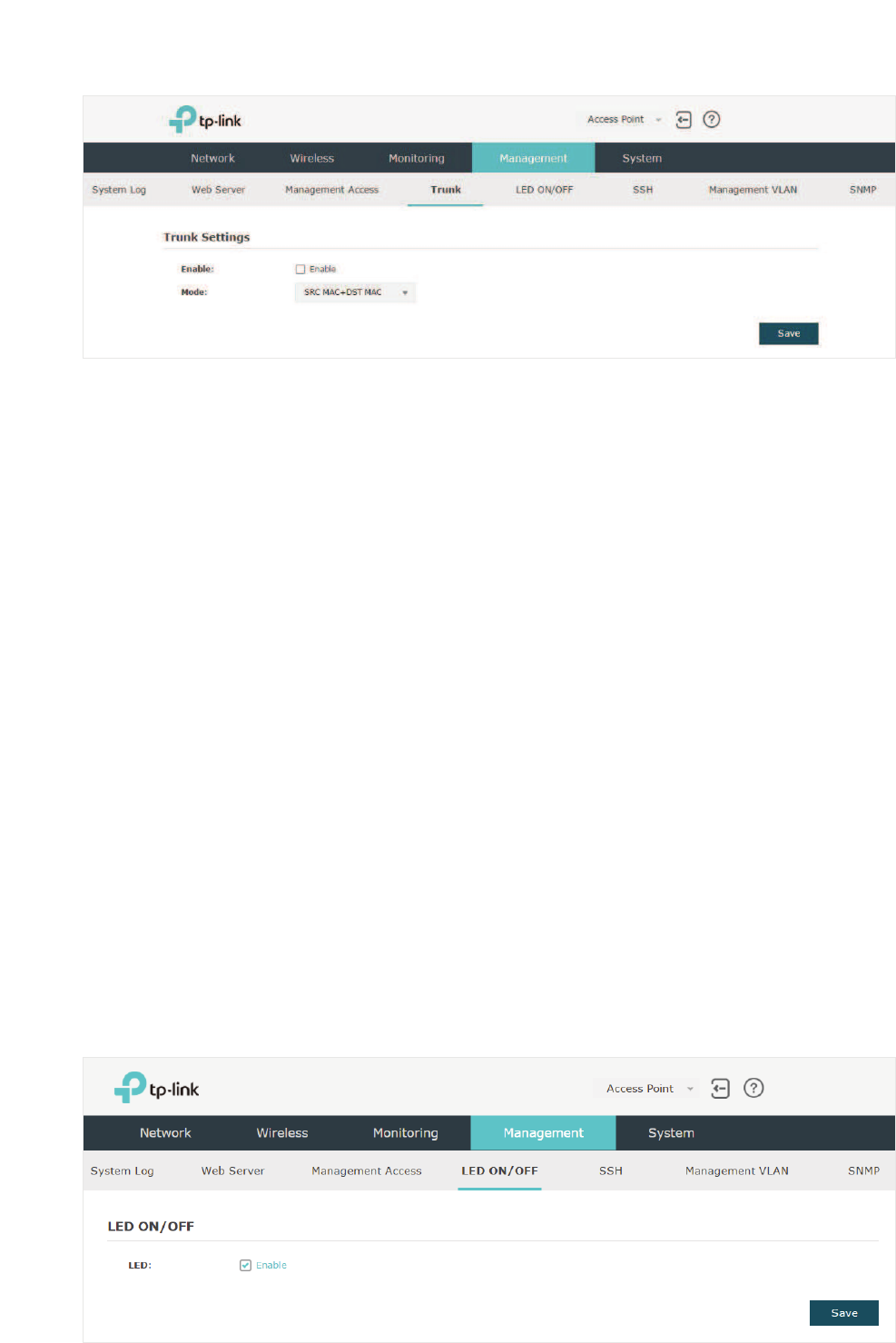
68
To configure Trunk, go to the 0DQDJHPHQW!7UXQN page.
Follow the steps below to configure Trunk on this page:
̝Check the box to enable 7UXQN.
̝Select the trunk algorithm mode from the drop-down list. Three options are available:
65&0$&'670$&'670$& and 65&0$&. Based on the selected algorithm mode,
the EAP determines which physical port is used to send out the received packet.
• With 65&0$&'670$& selected, the EAP determines the outgoing port based on
both the source and destination MAC addresses of the packet.
• With DST MAC selected, the EAP determines the outgoing port baesed on the
destination MAC address of the packet.
• With 65&0$& selected, the EAP determines the outgoing port based on the source
MAC address of the packet.
̝Click 6DYH.
4.5 &RQILJXUH/('
You can turn on or off the LED light of the EAP.
To configure LED, go to the 0DQDJHPHQW!/('212))page.
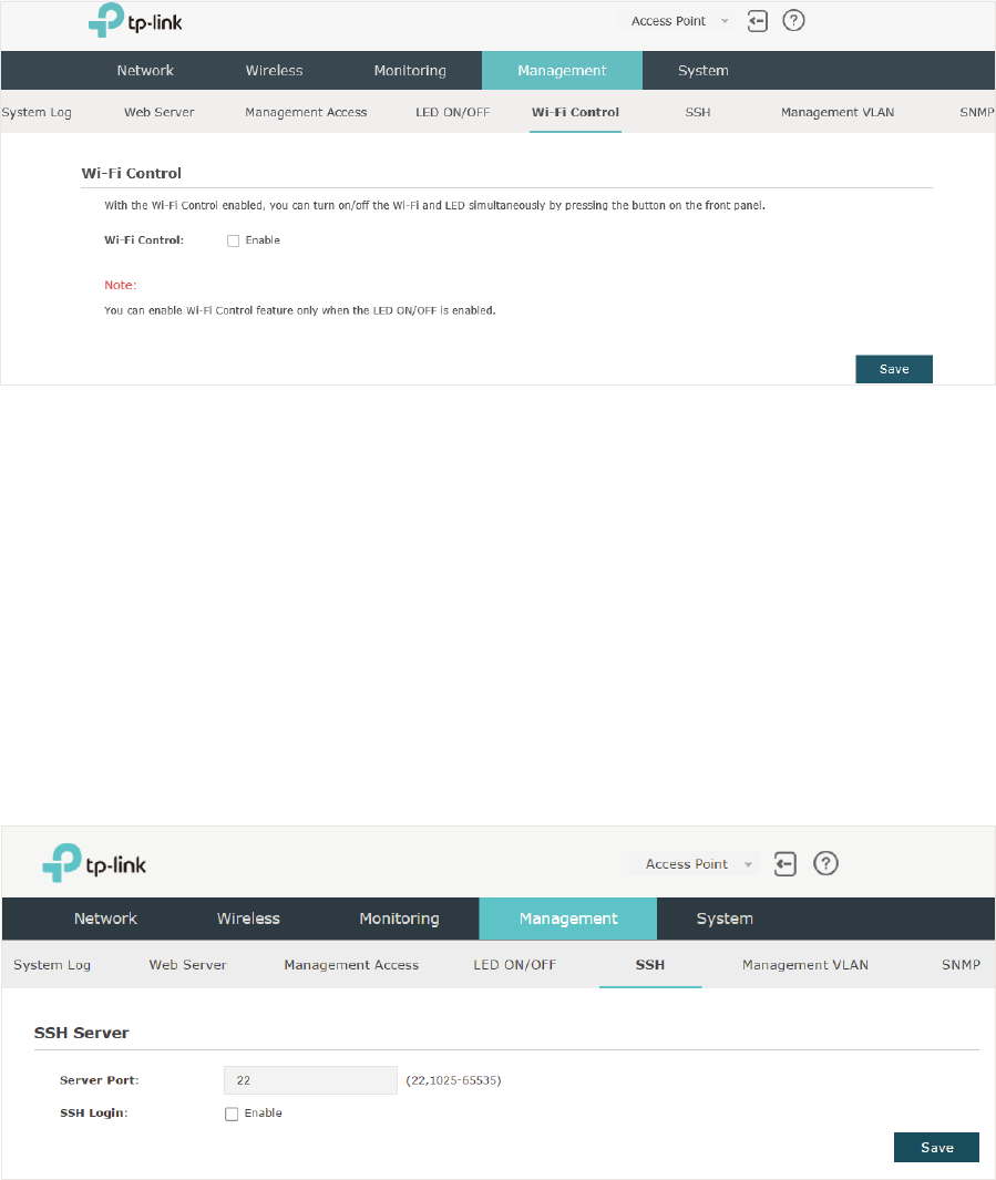
69
Check the box to turn on or turn off the LED light of the EAP, and click Save.
4.6 &RQILJXUH:L)L&RQWURO)RU($3:DOO
EAP115-Wall has an LED/Wi-Fi button on the front panel. With Wi-Fi Control enabled, you
can press the button to turn on or off both of the Wi-Fi and LED at the same time.
To configure Wi-Fi Control, go to the 0DQDJHPHQW!:L)L&RQWUROpage.
Check the box to enable Wi-Fi Control.
Note:
You can enable Wi-Fi Control only when the option /('212))is enabled.
4.7 &RQILJXUH66+
If you want to remotely log in to the EAP via SSH, you can deploy an SSH server on your
network and configure the SSH feature on the EAP.
To configure SSH, go to the 0DQDJHPHQW!66+page.
Follow the steps below to configure SSH on this page:
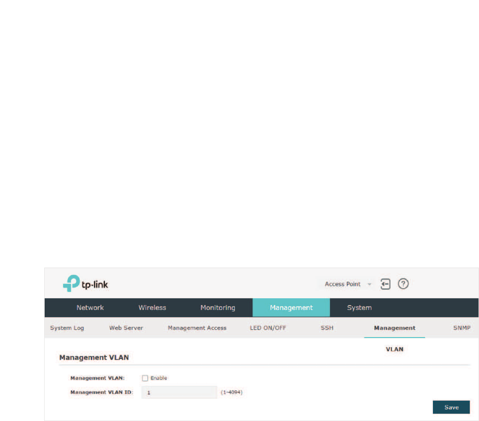
70
̝Enter the port number of the SSH server.
̝Check the box to enable66+/RJLQ. By default, it is disabled.
̝Click6DYH.
4.8 &RQILJXUH0DQDJHPHQW9/$1
Management VLAN provides a safer method to manage the EAP. With Management VLAN
enabled, only the hosts in the Management VLAN can access the web page of the EAP.
Since most hosts cannot process VLAN TAGs, you can connect the management host to
the network via a switch, and set up correct VLAN settings for the switches on the network
to ensure the communication between the host and the EAP in the Management VLAN.
To configure Management VLAN, go the 0DQDJHPHQW!0DQDJHPHQW9/$1 page.
Follow the steps below to configure Management VLAN on this page:
̝Check the box to enable0DQDJHPHQW9/$1.
̝Specify the VLAN ID of the management VLAN. Only the hosts in the Management
VLAN can log in to the EAP via the Ethernet port.
̝Click 6DYH.
4.9 &RQILJXUH6103
The EAP can be configured as an SNMP agent and work together with the SNMP manager.
Once the EAP has become an SNMP agent, it is able to receive and process request
messages from the SNMP manager. At present, the EAP supports SNMP v1 and v2c.
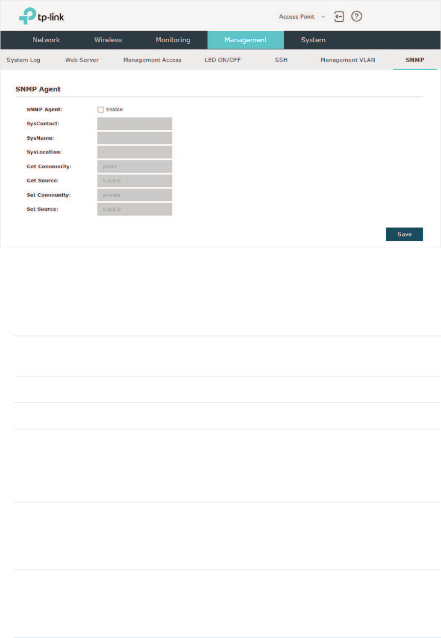
71
To configure the EAP as an SNMP agent, go to the 0DQDJHPHQW!6103 page.
Follow the steps below to complete the configuration on this page:
̝Check the box to enable 6103$JHQW.
̝Refer to the following table to configure the required parameters:
SysContact Enter the textual identification of the contact person for this managed
node.
SysName Enter an administratively-assigned name for this managed node.
SysLocation Enter the physical location of this managed node.
Get Community Community refers to a host group aiming at network management.
Get Community only has the read-only right of the device’s SNMP
information. The community name can be considered a group password.
The default setting is public.
Get Source Defines the IP address (for example, 10.10.10.1) for management
systems that can serve as Get Community to read the SNMP information
of this device. The default is 0.0.0.0, which means all hosts can read the
SNMP information of this device.
Set Community Set Community has the read and write right of the device’s SNMP
information. Enter the community name that allows read/write access to
the device’s SNMP information. The community name can be considered
a group password. The default setting is private.

72
Set Source Defines the IP address (for example, 10.10.10.1) for management
systems that can serve as Set Community to read and write the SNMP
information of this device. The default is 0.0.0.0, which means all hosts
can read and write the SNMP information of this device.
̝Click 6DYH.
Note:
Defining community can allow management systems in the same community to communicate
with the SNMP Agent. The community name can be seen as the shared password of the network
hosts group. Thus, for the security, we recommend that modify the default community name before
enabling the SNMP Agent service. If the field of community is blank, the SNMP Agent will not
respond to any community name.

73
5 &RQƮJXUHWKH6\VWHP
This chapter introduces how to configure the system of the EAP, including:
̝
gConfigure the User Account
̝
gConfigure the System Time
̝
gReboot and Reset the EAP
̝
gBackup and Restore the Configuration
̝
gUpdate the Firmware
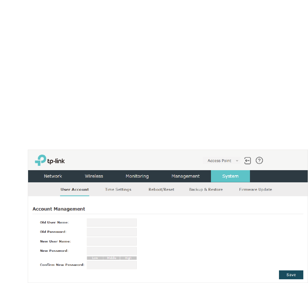
74
5.1 &RQILJXUHWKH8VHU$FFRXQW
Every EAP device has a user account, which is used to log in to the management page
of the EAP. When you start the EAP at the first time, the username and password of the
user account are both admin. After the first login, the system will require you to set a new
username and a new password for the user account. And then you can use the new user
account to log in to the EAP. Also, you can change your user account as needed.
Tips:
Please remember your user account well. If you forget it, reset the EAP to the factory defaults and
log in with the default user account (username and password are both admin).
To configure the user account, go to 6\VWHP!8VHU$FFRXQW page.
Follow the steps below to change your user account on this page:
̝Enter the old username and old password of your user account.
̝Specify a new username and a new password for your user account. The system
will automatically detect the strength of your entered password. For security, we
recommend that you set a password with high strength.
̝Retype the new password.
̝Click6DYH.
5.2 &RQILJXUHWKH6\VWHP7LPH
System time is the standard time for Scheduler and other time-based functions. The EAP
supports the basic system time settings and the Daylight Saving Time (DST) feature.
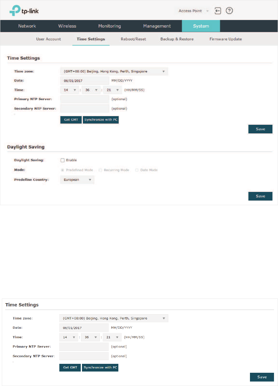
75
To configure the system time, go to the6\VWHP!7LPH6HWWLQJV page.
The following two sections introduce how to configure the basic system time settings and
the Daylight Saving Time feature.
&RQILJXUHWKH6\VWHP7LPH
In the 7LPH6HWWLQJV section, you can configure the system time. There are three methods
to set the system time:
Set the System Time Manually
,
Acquire the System Time From an
NTP Server
, and
Synchronize the System Time with PC’s Clock
.
Determine the way of setting the system time and follow the steps below to complete the
configurations:

76
̝
g6HWWKH6\VWHP7LPH0DQXDOO\
To set the system time manually, follow the steps below:
̝Configure the following three options on the page: 7LPH=RQH'DWHand Time.
Time Zone Select your time zone from the drop-down list. Here GMT means
Greenwich Mean Time.
Date Specify the current date in the format MM/DD/YYYY. MM means month,
DD means day and YYYY means year.
For example: 06/01/2017.
Time Specify the current time in the format HH/MM/SS. HH means hour, MM
means minute and SS means second.
It uses 24-hour system time. For example: 14:36:21.
̝Click6DYH.
Note:
The system time set manually will be lost after the EAP is rebooted.
̝
g$FTXLUHWKH6\VWHP7LPH)URPDQ1736HUYHU
To get the system time from an NTP server, follow the steps below:
̝Build an NTP server on your network and make sure that it is reachable by the EAP. Or
you can simply find an NTP server on the internet and get its IP address.
Note:
If you use an NTP server on the internet, make sure that the gateway address is set correctly on the
EAP. Otherwise, the EAP cannot get the system time from the NTP server successfully. To set the
gateway address, refer to
Configure the IP Address of the EAP.
̝Specify the NTP server for the EAP. If you have two NTP servers, you can set one of
them as the primary NTP server, and the other as the secondary NTP server. Once the
primary NTP server is down, the EAP can get the system time from the secondary NTP
server.
Primary NTP
Server
Enter the IP address of the primary NTP server.
1RWH
If you have only one NTP server on your network, enter the IP
address of the NTP server in this field.
Secondary NTP
Server
Enter the IP address of the secondary NTP server.
̝Click the button and the acquired system time will be displayed in the 'DWH
and Time fields.
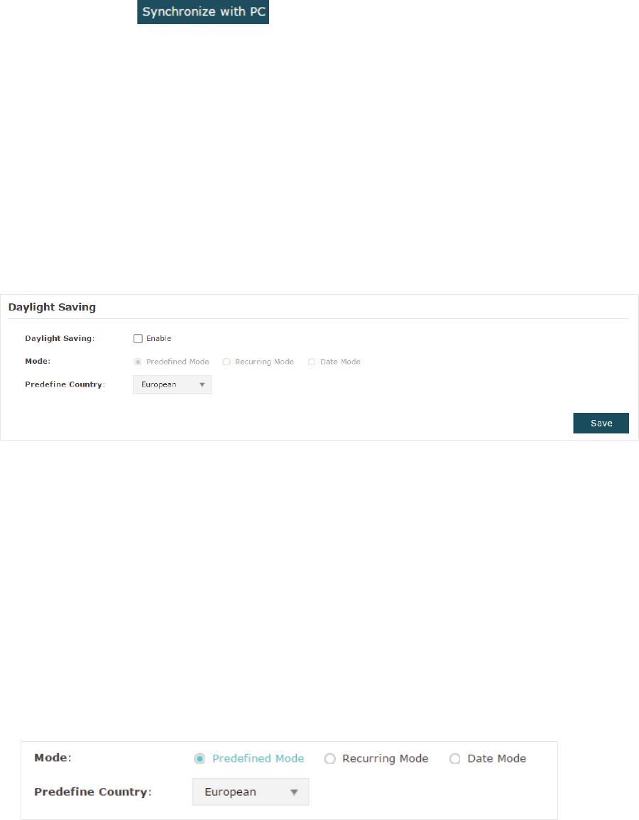
77
̝Click 6DYH.
̝
g6\QFKURQL]HWKH6\VWHP7LPHZLWK3&oV&ORFN
To synchronize the system time with the clock of your currently logged-in host,
follow the steps below:
̝Click the button and the synchronized system time will be displayed
in the 'DWH and Time fields.
̝Click6DYH.
Note:
The system time synchronized with PC’s clock will be lost after the EAP is rebooted.
&RQILJXUH'D\OLJKW6DYLQJ7LPH
Daylight saving time is the practice of advancing clocks during summer months so that
evening daylight lasts longer, while sacrificing normal sunrise times. The EAP provides
daylight saving time configuration.
Follow the steps below to configure daylight saving time:
̝Check the box to enable 'D\OLJKW6DYLQJ
̝Select the mode of daylight saving time. Three modes are available: 3UHGHILQHG0RGH
5HFXUULQJ0RGHand'DWH0RGH.
̝Configure the related parameters of the selected mode.
3UHGHILQHG0RGH
If you select Predefined Mode, choose your region from the drop-down list and the EAP
will use the predefined daylight saving time of the selected region.
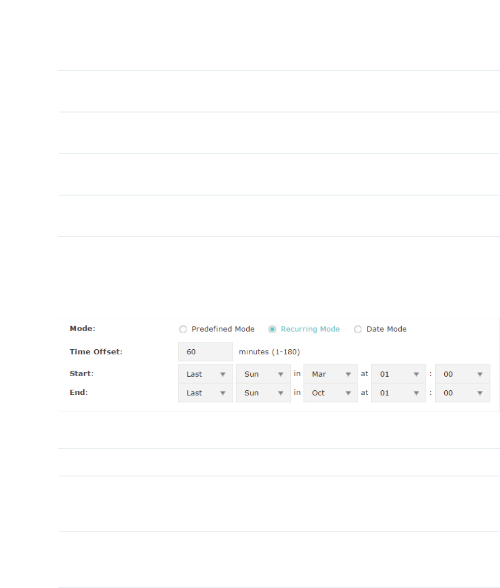
78
There are four regions provided: 86$(XURSHDQ $XVWULOLD and1HZ=HDODQG. The
following table introduces the predefined daylight saving time of each region.
USA From 2: 00 a.m. on the Second Sunday in March to 2:00 a.m. on the First
Sunday in November.
European From 1: 00 a.m. on the Last Sunday in March to 1:00 a.m. on the Last
Sunday in October.
Australia From 2:00 a.m. on the First Sunday in October to 3:00 a.m. on the First
Sunday in April.
New Zealand From 2: 00 a.m. on the Last Sunday in September to 3:00 a.m. on the
First Sunday in April.
5HFXUULQJ0RGH
If you select Recurring Mode, manually specify a cycle time range for the daylight saving
time of the EAP. This configuration will be used every year.
The following table introduces how to configure the cycle time range.
Time Offset Specify the time to set the clock forward by.
Start Specify the start time of daylight saving time. The interval between the
start time and end time should be more than 1 day and less than 1 year
(365 days).
End Specify the end time of daylight saving time. The interval between the
start time and end time should be more than 1 day and less than 1 year
(365 days).
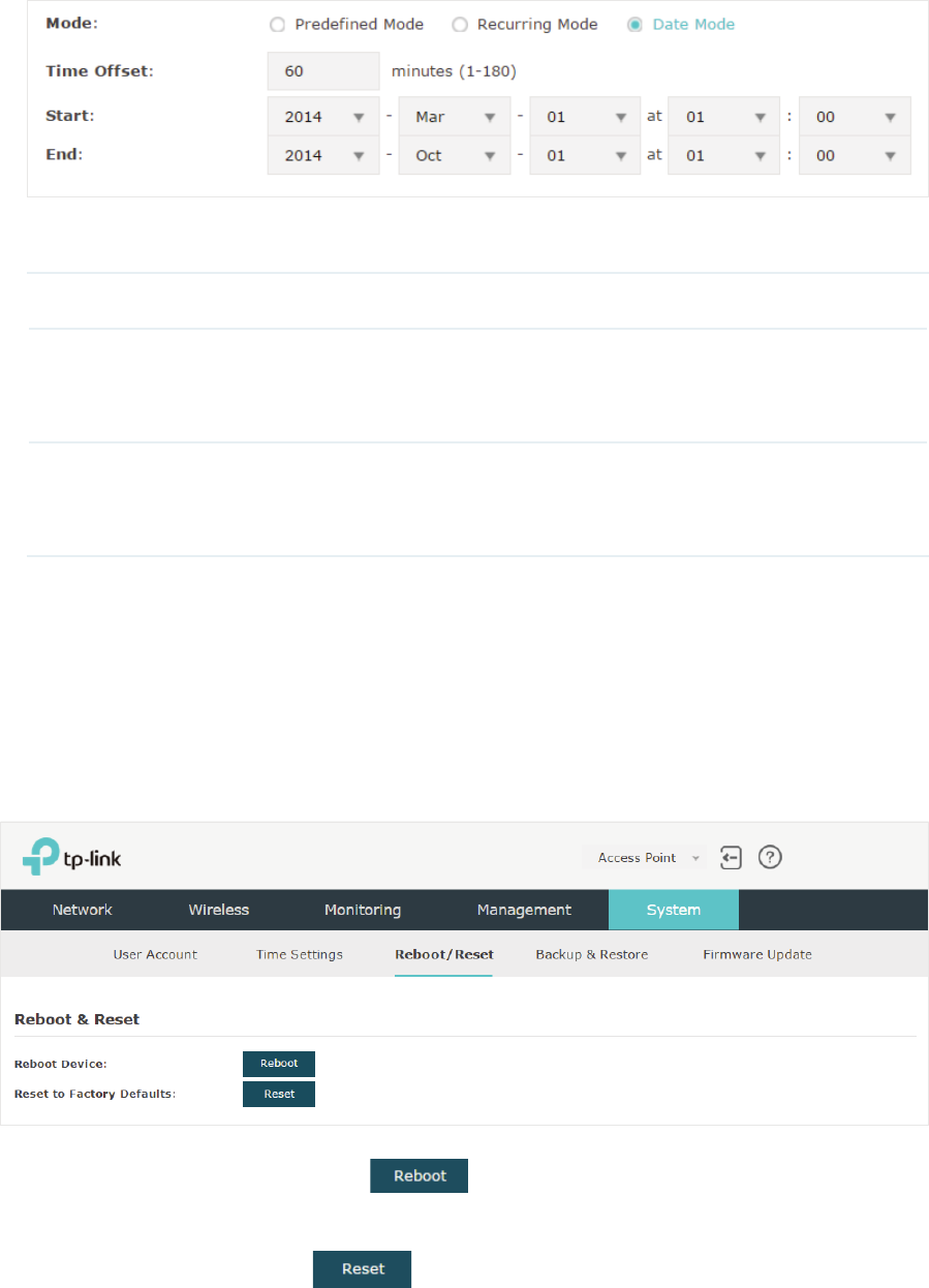
79
'DWH0RGH
If you select Date Mode, manually specify an absolute time range for the daylight saving
time of the EAP. This configuration will be used only once.
The following table introduces how to configure the absolute time range.
Time Offset Specify the time to set the clock forward by.
Start Specify the start time of daylight saving time. The interval between the
start time and end time should be more than 1 day and less than 1 year
(365 days).
End Specify the end time of daylight saving time. The interval between the
start time and end time should be more than 1 day and less than 1 year
(365 days).
̝Click 6DYH.
5.3 5HERRWDQG5HVHWWKH($3
You can reboot and reset the EAP according to your need.
To reboot and reset the EAP, go to the 6\VWHP!5HERRW5HVHW page.
• To reboot the EAP, click the button , and the EAP will be rebooted
automatically. Please wait without any operation.
• To reset the EAP, click the button , and the EAP will be reset to the factory
defaults automatically. Please wait without any operation.
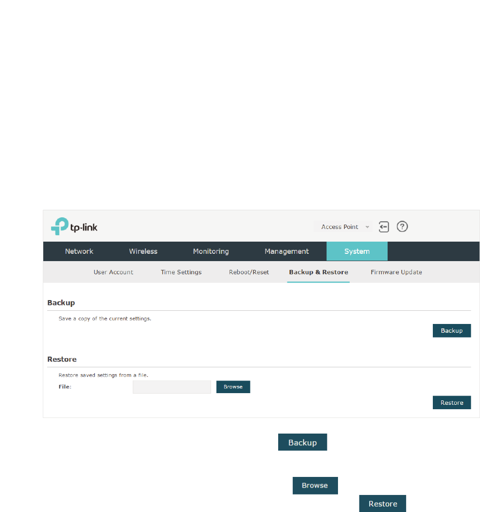
80
Note:
After reset, all the current configuration of the EAP will be lost. We recommend that you check
whether you have any configuration that needs to be backed up before resetting the EAP.
5.4 %DFNXSDQG5HVWRUHWKH&RQILJXUDWLRQ
You can save the current configuration of the EAP as a backup file and save the file to
your host. And if needed, you can use the backup file to restore the configuration. We
recommend that you backup the configuration before resetting or upgrading the EAP.
To backup and restore the configuration, go to the6\VWHP!%DFNXS5HVWRUH page.
• To backup the configuration, click the button in the Backup section, and the
backup file will be saved to the host automatically.
• To restore the configuration, click the button in the Restore section and
choose the backup file from the host. Then click the button to restore the
configuration.
5.5 8SGDWHWKH)LUPZDUH
We occasionally provide the firmware update files for the EAP products on our official
website. To get new functions of the EAP, you can check our official website and download
the update files to update the firmware of your EAP.
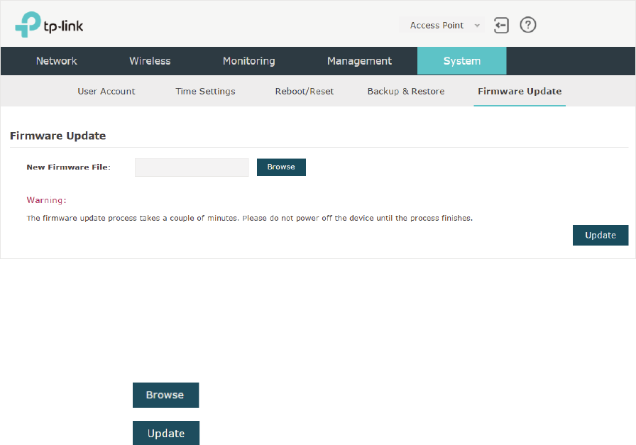
81
To update the firmware, go to the 6\VWHP!)LUPZDUH8SGDWH page.
Follow the steps below to update the firmware of your EAP:
̝Go to our website
www.tp-link.com
and search your EAP model. Download the proper
firmware file on the support page of the EAP.
̝Click the button , locate and choose the correct firmware file from your host.
̝Click the button to update the firmware of the EAP. After updated, the EAP will
be rebooted automatically.
Note:
The update process takes several minutes. To avoid damage to the EAP, please wait without any
operation until the update is finished.

82
6 $SSOLFDWLRQ([DPSOH
This chapter provides an application example about how to establish and manage a EAP
wireless network:
A restaurant wants to provide the wireless internet access for the employees and guests.
The restaurant now has a router, a switch, a dual-band EAP and a computer. Follow the
steps below to establish the wireless network:
1. Determine the Network Requirements
2. Build the Network Topology
3. Log in to the EAP
4. Configure the EAP
5. Test the Network
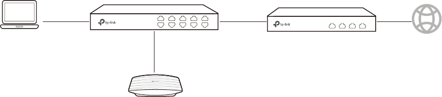
83
6.1 'HWHUPLQHWKH1HWZRUN5HTXLUHPHQWV
Before starting to build the network, we need to first analyze and determine the network
requirements. In this restaurant example, the network requirements are as follows:
• On both 2.4GHz and 5GHz bands, there are two SSIDs needed: one for the restaurant
employees and one for the guests.
• In order to advertise the restaurant, the Portal feature needs to be configured on the
SSIDs for the guests. In this way, the guests who have passed the portal authentication
will be redirected to the restaurant’s official website KWWSZZZUHVWDXUDQWFRP.
• The employees of the restaurant can use the correct password to access the internet
and do not need to pass the portal authentication. For security, the SSIDs for the
employees should be encrypted with WPA2-PSK.
• To reduce power consumption, the Scheduler feature needs to be configured. The radio
should operate only during the working time (9:00 am to 22:00 pm).
6.2 %XLOGWKH1HWZRUN7RSRORJ\
Build the network topology as the following figure shows.
EAP
Management Host
Switch Router (DHCP Server)
LAN: 192.168.88.1 Internet
• The router is the gateway of the network and acts as a DHCP server to assign dynamic
IP addresses to the management host, EAP and clients. The LAN IP of the router is
192.168.88.1/24.
• Connect the switch to the LAN port of the router.
• Connect the management host and the EAP to the switch. The IP address mode of
the management host and EAP is dynamic, which means that they will get dynamic IP
addresses from the router.
Tips:
If the router has more than one LAN port, we can also respectively connect the management host
and the EAP to the LAN ports of the router.
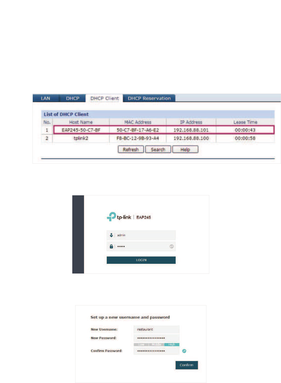
84
6.3 /RJLQWRWKH($3
After building the network topology, follow the steps below to log in to the web page of the
EAP:
̝On the management host, launch the web browser and enter “192.168.88.1” in the
address bar. Then log in to the router and find the IP address of the EAP. As the
following figure shows, the IP address of the EAP is 192.168.88.101.
̝Enter “192.168.88.101” in the address bar to load the login page of the EAP. Type the
default username and password (both admin) in the two fields and click LOGIN.
̝In the pop-up window, specify a new username and a new password for the user
account. Click Confirm.
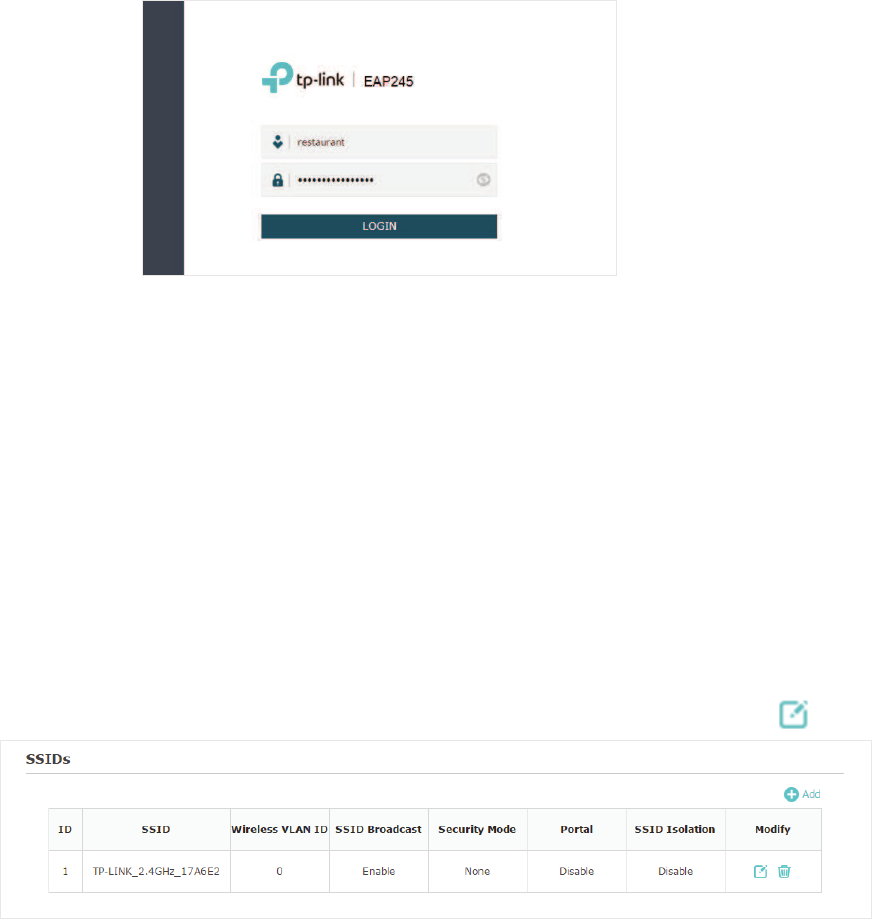
85
̝Enter the new username and new password and click LOGIN. Then we can enter the
web page of the EAP.
6.4 &RQILJXUHWKH($3
To achieve the network requirements in this application example, we need to
Configure
SSIDs
Configure Portal Authentication
and
Configure Scheduler
.
&RQILJXUH66,'V
Follow the steps below to respectively configure SSIDs for the employees and guests on
the 2.4GHz band and 5GHz band:
̝Go to the :LUHOHVV!:LUHOHVV6HWWLQJV page.
̝In the SSIDs section, there is already a default SSID on the 2.4GHz band. Click .
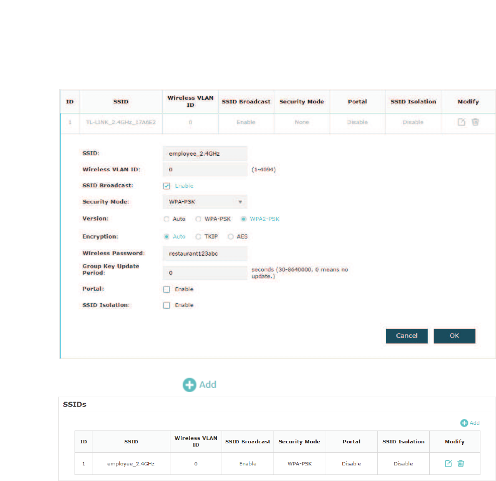
86
̝The following page will appear. Configure this SSID for the employees. Change SSID
to “employee_2.4GHz”, select the 6HFXULW\0RGH as “WPA2-PSK”, and specify the
:LUHOHVV3DVVZRUG as “restaurant123abc“. Click 2..
̝On the same page, click to add a new SSID.
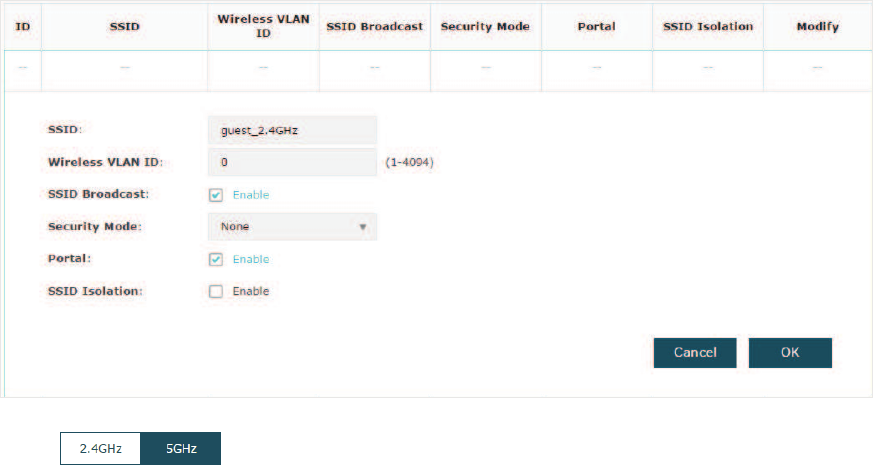
87
̝The following page will appear. Configure this SSID for the guests. Change SSID to
“guest_2.4GHz“, keep the 6HFXULW\0RGH as “None” and check the box to enable the
3RUWDO feature for this SSID. Click 2..
̝Click to enter the configuration page for the 5GHz band. Similarly to
the configurations for the 2.4GHz band, configure two SSIDs for the employees and
guests on the 5GHz band.
&RQILJXUH3RUWDO$XWKHQWLFDWLRQ
Follow the steps below to configure portal authentication:
̝Go to the :LUHOHVV!3RUWDO page.
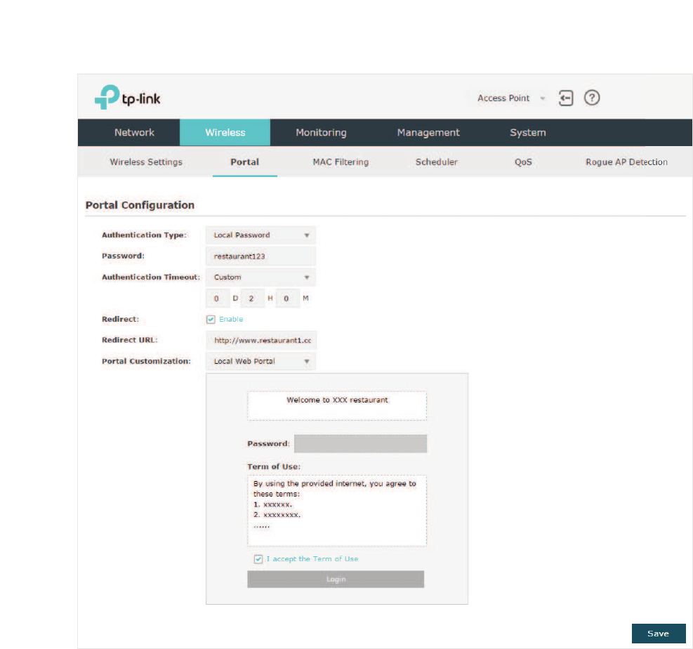
88
̝Configure the portal feature as the following figure shows.
̝Select the $XWKHQWLFDWLRQ7\SH as “Local Password” and specify the3DVVZRUGas
“restaurant123”.
̝Configure $XWKHQWLFDWLRQ7LPHRXW. Here we customize the timeout as 2 hours. It
means that guests will be logged out after they have been authenticated for 2 hours.
To continue to use the internet service, these guests need to enter the password to
pass the portal authentication once again.
̝Check the box to enable5HGLUHFW, and enter the website of the restaurant: KWWS
ZZZUHVWDXUDQWFRP.
̝&RQƮJXUHWKHDXWKHQWLFDWLRQSDJH6SHFLI\WKHWLWOHDQGWKHWHUPRIXVH7RDFFHVV
the internet, guests need to enter the correct password in the 3DVVZRUGfield,
accept the Term of Use, and click the /RJLQbutton.
̝Click 6DYH.
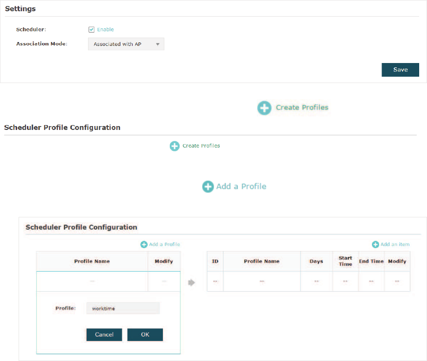
89
&RQILJXUH6FKHGXOHU
Follow the steps below to schedule the radio to operate only during the working time (9:00
am to 22:00 pm).
̝Go to the :LUHOHVV!6FKHGXOHU page.
̝In the 6HWWLQJV section, check the box to enable6FKHGXOHU, and select the $VVRFLDWLRQ
Mode as “Associated with AP“. Click6DYH.
̝In the 6FKHGXOHU3URILOH&RQILJXUDWLRQ section, click .
̝The following page will appear. Click DQGVSHFLI\WKHSURƮOHQDPHDV
“worktime”. Click 2..
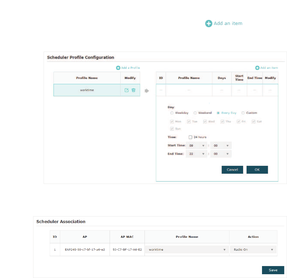
90
̝&KRRVHWKHQHZO\DGGHGSURƮOHpZRUNWLPHqDQGFOLFN . Then the item
configuraiton page will appear. Specify the time range as everyday 9:00 to 22:00.
Click 2..
̝In the6FKHGXOHU$VVRFLDWLRQ section, select “worktime“ in the 3URILOH1DPH column
and select “Radio On” in the $FWLRQcolumn. Click 6DYH.
6.5 7HVWWKH1HWZRUN
To ensure that the employees and guests can surf the internet via the wireless network,
we can use a client device, such as a telephone, to test whether the SSIDs are working
normally.
• To test the SSIDs for the employees, follow the steps below:
̝Enable the Wi-Fi feature of the client device.
̝Choose the SSID “employee_2.4GHz“ or “employee_5GHz“ among the detected
SSIDs.
̝Enter the password “restaurant123abc“ to join the wireless network.
̝Check whether internet websites can be visited successfully.
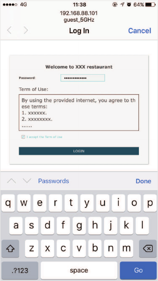
91
• To test the SSIDs for the guests, follow the steps below:
̝Enable the Wi-Fi feature of the client device.
̝Choose the SSID “guest_2.4GHz“ or “guest_5GHz“ among the detected SSIDs.
̝The default web browser on the device will pop up and the authentication page will
appear. Enter the password “restaurant123”, check the box to accept the term of
use, and click the LOGIN button.
Tips:
Generally, the web browser pops up automatically. But if the web browser does not pop up, we
can manually launch the web browser and visit any http website. Then the authentication page will
appear.
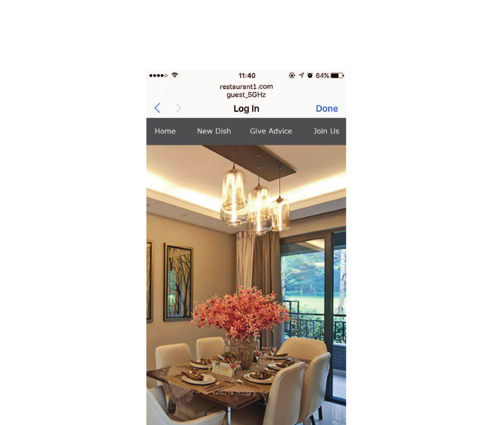
92
̝If the network is working normally, we will be redirected to the website of the
restaurant:KWWSZZZUHVWDXUDQWFRP.
FCC STATEMENT
This equipment has been tested and found to comply with the limits for a Class B digital
device, pursuant to part 15 of the FCC Rules. These limits are designed to provide reasonable
protection against harmful interference in a residential installation. This equipment
generates, uses and can radiate radio frequency energy and, if not installed and used in
accordance with the instructions, may cause harmful interference to radio communications.
However, there is no guarantee that interference will not occur in a particular installation. If
this equipment does cause harmful interference to radio or television reception, which can
be determined by turning the equipment off and on, the user is encouraged to try to correct
the interference by one or more of the following measures:
gReorient or relocate the receiving antenna.
gIncrease the separation between the equipment and receiver.
gConnect the equipment into an outlet on a circuit different from that to which the receiver is
connected.
gConsult the dealer or an experienced radio/ TV technician for help.
This device complies with part 15 of the FCC Rules. Operation is subject to the following two
conditions:
1) his device may not cause harmful interference.
2) This device must accept any interference received, including interference that may cause
undesired operation.
Any changes or modifications not expressly approved by the party responsible for
compliance could void the user’s authority to operate the equipment.
Note: The manufacturer is not responsible for any radio or TV interference caused by
unauthorized modifications to this equipment. Such modifications could void the user’s
authority to operate the equipment.
FCC RF Radiation Exposure Statement:
This equipment complies with FCC RF radiation exposure limits set forth for an uncontrolled
environment. This device and its antenna must not be co-located or operating in conjunction
with any other antenna or transmitter.
“To comply with FCC RF exposure compliance requirements, this grant is applicable to only
Mobile Configurations. The antennas used for this transmitter must be installed to provide
a separation distance of at least 20 cm from all persons and must not be colocated or
operating in conjunction with any other antenna or transmitter.”

&(0DUN:DUQLQJ
This is a class B product. In a domestic environment, this product may cause radio
interference, in which case the user may be required to take adequate measures.
23(5$7,1*)5(48(1&<WKHPD[LPXPWUDQVPLWWHG
SRZHU
2412MHz—2472MHz(20dBm)
5180MHz—5240MHz(23dBm) (EAP225/EAP245/EAP320/EAP330/EAP225-Outdoor)
5725MHz—5825MHz(30dBm) (EAP225-Outdoor)
(8GHFODUDWLRQRIFRQIRUPLW\
TP-Link hereby declares that the device is in compliance with the essential requirements and
other relevant provisions of directives 2014/53/EU, 2009/125/EC and 2011/65/EU.
The original EU declaration of conformity may be found at http://www.tp-link.com/en/ce.
5)([SRVXUH,QIRUPDWLRQ
This device meets the EU requirements (2014/53/EU Article 3.1a) on the limitation of
exposure of the general public to electromagnetic fields by way of health protection.
The device complies with RF specifications when the device used at 20 cm from your body.
1DWLRQDO5HVWULFWLRQV($3($3($3($3
Restricted to indoor use.
&DQDGLDQ&RPSOLDQFH6WDWHPHQW
This device complies with Industry Canada license-exempt RSSs. Operation is subject to the
following two conditions:
1) This device may not cause interference, and

2) This device must accept any interference, including interference that may cause
undesired operation of the device.
Le présent appareil est conforme aux CNR d’Industrie Canada applicables aux appareils
radio exempts de licence. L’exploitation est autorisée aux deux conditions suivantes :
1) l’appareil ne doit pas produire de brouillage;
2) l’utilisateur de l’appareil doit accepter tout brouillage radioélectrique subi, meme si le
brouillage est susceptible d’en compromettre le fonctionnement.
For EAP110-Outdoor:
This radio transmitter (IC: 8853A-EAP110-Outdoor/ Model: EAP110-Outdoor) has been
approved by Industry Canada to operate with the antenna types listed below with the
maximum permissible gain indicated. Antenna types not included in this list below, having
a gain greater than the maximum gain indicated for that type, are strictly prohibited for use
with this device.
Le présent émetteur radio (IC: 8853A-EAP110-Outdoor / Model: EAP110-Outdoor) a été
approuvé par Industrie Canada pour fonctionner avec les types d'antenne énumérés ci-
dessous et ayant un gain admissible maximal. Les types d'antenne non inclus dans cette
liste ci-dessous et dont le gain est supérieur au gain maximal indiqué, sont strictement
interdits pour l'exploitation de l'émetteur.
Antenna Two 2.4GHz 3dBi external omnidirectional antennas
For EAP225-Outdoor:
This radio transmitter (IC: 8853A-EAP225OD / Model: EAP225-Outdoor) has been approved
by Industry Canada to operate with the antenna types listed below with the maximum
permissible gain indicated. Antenna types not included in this list below, having a gain greater
than the maximum gain indicated for that type, are strictly prohibited for use with this device.
Le présent émetteur radio (IC: 8853A-EAP225OD / Model: EAP225-Outdoor) a été approuvé
par Industrie Canada pour fonctionner avec les types d'antenne énumérés ci-dessous
et ayant un gain admissible maximal. Les types d'antenne non inclus dans cette liste ci-
dessous et dont le gain est supérieur au gain maximal indiqué, sont strictement interdits
pour l'exploitation de l'émetteur.
Antenna Two 2.4GHz 3dBi external omnidirectional antennas
Two 5GHz 4dBi external omnidirectional antennas
Caution (EAP320/EAP330/EAP225/EAP245/EAP225-Outdoor)
1) The device for operation in the band 5150–5250 MHz is only for indoor use to reduce the
potential for harmful interference to co-channel mobile satellite systems;
2) For devices with detachable antenna(s), the maximum antenna gain permitted for devices
in the bands 5250-5350 MHz and 5470-5725 MHz shall be such that the equipment still
complies with the e.i.r.p. limit; (For EAP225-Outdoor only)
3) For devices with detachable antenna(s), the maximum antenna gain permitted for devices
in the band 5725-5850 MHz shall be such that the equipment still complies with the e.i.r.p.
limits specified for point-to-point and non-point-to-point operation as appropriate; and
The high-power radars are allocated as primary users (i.e. priority users) of the bands 5250-
5350 MHz and 5650-5850 MHz and that these radars could cause interference and/or
damage to LE-LAN devices.
DFS (Dynamic Frequency Selection) products that operate in the bands 5250- 5350 MHz,
5470-5600MHz, and 5650-5725MHz. (For EAP225-Outdoor only)
Avertissement
1) Le dispositif fonctionnant dans la bande 5150-5250 MHz est réservé uniquement pour une
utilisation à l’intérieur afin de réduire les risques de brouillage préjudiciable aux systèmes de
satellites mobiles utilisant les mêmes canaux;
2) Le gain maximal d'antenne permis pour les dispositifs avec antenne(s) amovible(s) utilisant
les bandes 5250-5350 MHz et 5470-5725 MHz doit se conformer à la limitation P.I.R.E.;
3) Le gain maximal d’antenne permis pour les dispositifs avec antenne(s) amovible(s) utilisant
la bande 5725-5850 MHz doit se conformer à la limitation P.I.R.E spécifiée pour l’exploitation
point à point et non point à point, selon le cas.
En outre, les utilisateurs devraient aussi être avisés que les utilisateurs de radars de haute
puissance sont désignés utilisateurs principaux (c.-à-d., qu’ils ont la priorité) pour les bandes
5250-5350 MHz et 5650-5850 MHz et que ces radars pourraient causer du brouillage et/ou
des dommages aux dispositifs LAN-EL.
Les produits utilisant la technique d'atténuation DFS (sélection dynamique des fréquences)
sur les bandes 5250- 5350 MHz, 5470-5600MHz et 5650-5725MHz.
5DGLDWLRQ([SRVXUH6WDWHPHQW
This equipment complies with ISEDC radiation exposure limits set forth for an uncontrolled
environment. This equipment should be installed and operated with minimum distance (20cm
for EAP110/EAP115/EAP245/EAP115-Wall/EAP110-Outdoor/EAP225-Outdoor, 35cm for
EAP 320, 46cm for EAP330, and 24cm for EAP225) between the radiator & your body.

'ÆFODUDWLRQGoH[SRVLWLRQDX[UDGLDWLRQV
Cet équipement est conforme aux limites ISEDC d’exposition aux rayonnements établies
pour un environnement non contrôlé. Cet équipement doit être installé et utilisé à une
distance minimale (entre la source de rayonnement et votre corps) indiquée ci-après :
Modèle 'LVWDQFH
($3($3($3
($3:DOO($32XWGRRU
($32XWGRRU
FP
($3 FP
($3 FP
($3 FP
,QGXVWU\&DQDGD6WDWHPHQW
CAN ICES-3 (B)/NMB-3(B)
.RUHD:DUQLQJ6WDWHPHQWV
╏䟊Gⶊ㍶㍺゚⓪G㤊㣿㭧G㩚䕢䢒㔶GṖ⓻㎇㧊G㧞㦢GU
цѧѥћѪѡѩѨќѧѩџѫѽѡѥљїѤѥўњѽћѤѥѨѦѧїљџѢїѣџ ѨџѨѩќѣџ ъѡѧшмцчхѤї љѽћѦѥљѽћѤѽѨѩѳ
љџѣѥњїѣѤѥѧѣїѩџљѤџѬћѥѡѪѣќѤѩѽљѩїљџѣѥњїѣѰѥѦќѧќћјїѮќѤѽѮџѤѤџѣџўїѡѥѤѥћїљѮџѣџ
їѡѩїѣџъѡѧїѾѤџ
6DIHW\,QIRUPDWLRQ
When product has power button, the power button is one of the way to shut off the product;
When there is no power button, the only way to completely shut off power is to disconnect
the product or the power adapter from the power source.
gKeep the device away from water, fire, humidity or hot environments.

gDo not attempt to disassemble, repair, or modify the device.
gDo not use damaged charger or USB cable to charge the device.
gDo not use any other chargers than those recommended
gDo not use the device where wireless devices are not allowed.
gAdapter shall be installed near the equipment and shall be easily accessible.
For EAP110/EAP225/EAP245/EAP110-Outdoor/EAP225-Outdoor:
Use only power supplies which are provided by manufacturer and in the original
packing of this product. If you have any questions, please don’t hesitate to contact us.
1&&1RWLFH
⌘ʽ
ᬊվ࣏⦷䴫⌒䕫ሴᙗ䴫㇑⨶䗖⌅
ㅜॱҼọ㏃රᔿ䂽䅹ਸṬѻվ࣏⦷ሴ乫䴫ˈ䶎㏃䁡ਟˈޜਨǃ୶㲏ᡆ֯⭘㘵൷нᗇ㠚䆺
ᴤ乫⦷ǃ࣐བྷ࣏⦷ᡆ䆺ᴤ䁝䀸ѻ⢩ᙗᡆ࣏㜭DŽ
ㅜॱഋọվ࣏⦷ሴ乫䴫ѻ֯⭘нᗇᖡ丯伋㡚ᆹޘ৺ᒢᬮਸ⌅䙊㹼˗㏃Ⲭ⨮ᴹᒢᬮ⨮䊑ᱲˈ
៹・ণڌ⭘ˈі᭩ழ㠣❑ᒢᬮᱲᯩᗇ㒬㒼֯⭘DŽࡽ丵ਸ⌅䙊ؑˈᤷ䴫ؑ㾿ᇊᾝѻ❑㐊䴫ؑDŽ
վ࣏⦷ሴ乫䴫䴰ᗽਇਸ⌅䙊ؑᡆᐕᾝǃ、ᆨԕ৺䟛Ⱳ⭘䴫⌒䕫ሴᙗ䴫䁝ۉѻᒢᬮDŽ
For EAP225-Outdoor.
ᯬ5.25GHz㠣5.35GHz॰ฏޗѻ❑㐊䁝ۉⲴ䆖㚢᰾
ᐕ乫⦷5.250~5.350GHz䂢乫⇥䲀ᯬᇔޗ֯⭘DŽ
%60,1RWLFH
ᆹޘ䄞䂒৺⌘һ丵
g䃻֯⭘㼍䴫Ⓚ៹ಘᡆਚ㜭᤹➗ᵜ⭒૱⌘᰾Ⲵ䴫Ⓚ于ර֯⭘ᵜ⭒૱DŽ
g▄ᵜ⭒૱ѻࡽ䃻ݸᤄᦹ䴫Ⓚ㐊DŽ䃻य֯⭘⏢億ǃತ䵗▄ࣁᡆ★ᐳ䙢㹼▄DŽ
g⌘䱢▞ˈ䃻यሷ≤ᡆަԆ⏢億▁⚁ࡠᵜ⭒૱кDŽ
gᨂ㠷䮻ਓ䙊付֯⭘ˈԕ⻪؍ᵜ⭒૱Ⲵਟ䶐і䱢→䙾⟡ˈ䃻यຎᡆ㾶㫻䮻ਓDŽ
g䃻यሷᵜ⭒૱㖞᭮ᯬ䶐䘁⟡ⓀⲴൠᯩDŽ䲔䶎ᴹ↓ᑨⲴ䙊付ˈࡷнਟ᭮൘ᇶ䮹ս㖞ѝDŽ
g䃻н㾱⿱㠚ᢃ䮻⇬ˈн㾱ే䂖㠚㹼㏝؞ᵜ⭒૱ˈ䃻⭡ᦸ℺ⲴሸᾝӪ༛䙢㹼↔丵ᐕDŽ
䲀⭘⢙䌚ਜ਼ᴹᛵ⋱⁉⽪㚢᰾ᴨ
⭒૱ݳԦち
䲀⭘⢙䌚৺ަॆᆨㅖ㲏
䢋
3E
䧈
&G
⊎
+J
ޝܩ䢫
&U9,
ཊⓤ㚟㤟
3%%
ཊⓤҼ㤟䟊
3%'(
3&% ○ ○ ○ ○ ○ ○
ཆ⇬ ○ ○ ○ ○ ○ ○
䴫Ⓚ䚙䝽ಘ —○ ○ ○ ○ ○
ۉ㘳ƻ㌫ᤷ䂢丵䲀⭘⢙䌚ѻⲮ࠶∄ਜ਼䟿ᵚ䎵ࠪⲮ࠶∄ਜ਼䟿สⓆ٬DŽ
ۉ㘳—㌫ᤷ䂢丵䲀⭘⢙䌚⛪ᧂ䲔丵ⴞDŽ
(EAP320/EAP330/EAP225/EAP245/EAP225-Outdoor)
For EU/EFTA, this product can be used in the following countries:
AT BE BG &+ &< CZ DE '.
EE EL ES ), )5 +5 +8 IE
IS IT LI LT LU /9 MT NL
NO 3/ 37 52 SE SI 6. 8.
([SODQDWLRQRIWKHV\PEROVRQWKHSURGXFWODEHO
Symbol Explanation
DC voltage

RECYCLING
This product bears the selective sorting symbol for Waste electrical
and electronic equipment (WEEE). This means that this product must be
handled pursuant to European directive 2012/19/EU in order to be recycled
or dismantled to minimize its impact on the environment.
User has the choice to give his product to a competent recycling
organization or to the retailer when he buys a new electrical or electronic
equipment.
(EAP110/EAP115/EAP225/EAP245/EAP320/EAP330/EAP115-Wall)
Indoor use only

&23<5,*+775$'(0$5.6
Specifications are subject to change without notice. is a registered trademark
of TP-Link Technologies Co., Ltd. Other brands and product names are trademarks or
registered trademarks of their respective holders.
No part of the specifications may be reproduced in any form or by any means or used to
make any derivative such as translation, transformation, or adaptation without permission
from TP-Link Technologies Co., Ltd. Copyright © 2017 TP-Link Technologies Co., Ltd.. All
rights reserved.