TP Link Technologies EAP220 N600 Wireless Dual Band Gigabit Access Point User Manual EAP220 Uaser Manual Revised0416
TP-Link Technologies Co., Ltd. N600 Wireless Dual Band Gigabit Access Point EAP220 Uaser Manual Revised0416
EAP220_Uaser Manual-Revised0416

Installation Guide
Wireless N Gigabit Access Point
EAP120 / EAP220
CONTENTS
About This Installation Guide
This guide is designed to familiarize you with the general layout of the EAP,
describe how to deploy the device in your network and how to configure the
device. Your EAP has more features and functionalities which can be found in the
User Guide.
Network Topology Requirements —————————————— 01
Overview ————————————————————————— 02
Hardware Installation ——————————————————— 04
1. Installation Requirements ....................................................... 04
2. Mounting Bracket ................................................................... 04
3. Installation ............................................................................ 05
4. Powering Mode ...................................................................... 09
Getting Started with the EAP ———————————————— 11
Q&A ——————————————————————————— 14
Specications ——————————————————————— 15
Technical Support ————————————————————— 16
01
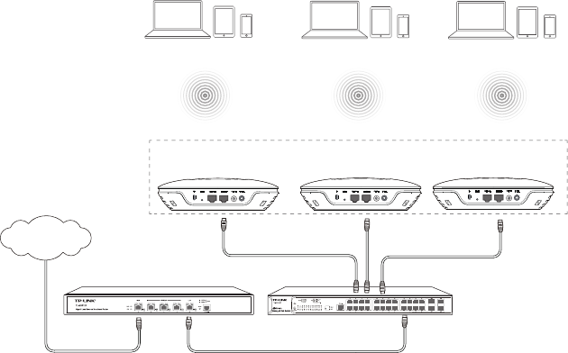
Network Topology Requirements
Typical topology for the EAP is described below.
Router
Internet
Switch
Master EAP Slave EAPSlave EAP
Enwuvgt
Typical Topology
The EAP120 and EAP220 provide two management modes: Cluster and Standalone.
By default,
the management mode is Cluster. In this mode, all the EAPs in the
same LAN will form a Cluster, and a Master EAP will be elected among them to
manage the other EAPs, called Slave EAPs.
A DHCP server is required in the local network to assign IP addresses to the EAPs.
A router usually acts as the DHCP server.
Typically, a PoE switch can be used to provide Power over Ethernet for each EAP.
Or, each EAP must be powered with a power adapter individually.
02
Overview
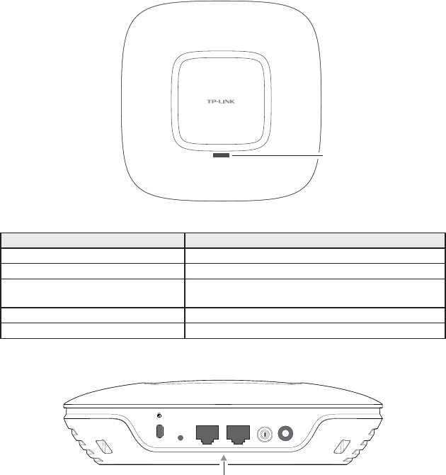
■LED Explanation
System LED
Top View of the EAP
LED Status Indication
Quickly flashing green System initialization is complete.
Solid green The device is working properly.
Slowly flashing red The system is abnormal. RAM, Flash, Ethernet,
WLAN or firmware may be malfunctioning.
Quickly flashing yellow Firmware is being updated.
Alternating red/green/yellow twice The device is being reset.
■Interface Panel
RESET CONSOLE ETHERNET ON/OFF POWER
ARROW 1
Interface Panel of the EAP
The interface panel components of the EAP, from left to right, are described in the
following list:
Kensington Security Slot
Secure the lock into the slot to prevent the device from being stolen.
03
RESET
With the device powered on, press and hold the RESET button for about 8 seconds,
and then release the button. The device will restore to factory default settings.
CONSOLE
This port is used to connect with the serial port of a computer or a terminal to
check and monitor simple system information of the device.
ETHERNET
This port is for connection to a router or switch to transmit and receive data as well
as to a PSE device for power supply. Power sourcing equipment (PSE) is a device
such as a switch that provides power over Ethernet cables to linked devices.
ON/OFF
Press this button to power on/off the device. Please remember to press it to use
the device.
POWER
The power jack is for connection to the power adapter. Please use the power
adapter provided. Refer to Powering Mode to learn how to power the device via
PoE and power adapter.
ARROW 1
To align with ARROW 2 in the mounting bracket before the EAP locks into place.
Please refer to Mounting Bracket to locate ARROW 2.
04
Hardware Installation
The EAP can be wall or ceiling mounted and can be powered via a PSE device
or the provided adapter. Please suitably arrange your wire layout before the
mounting.
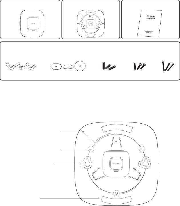
1. Installation Requirements
Check and prepare the following items in the package for installation.
One EAP
One Mounting Bracket
One Installation Guide
Three Nuts/ Washers/ Plastic Extending Tubes/ Self-tapping Screws/ Pan Head Screws
Besides the above installation kits, these tools may be needed for hardware
installation: pencil, ruler, drill, hammer, screwdriver and ladder.
2. Mounting Bracket
The following figure describes the structure of the mounting bracket.
Locking clip
ARROW 2, to align with
ARROW 1 under the
interface panel
Ceiling mounting slot
Wall mounting slot
Mounting Bracket
05
3. Installation
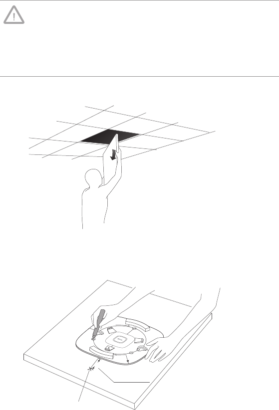
■Ceiling Mounting
Note:
■Make sure the thickness of the ceiling is less than 18mm and
the ceiling can bear at least five kilograms.
■If the ceiling is made of low-strength material like gypsum, it is
not recommended to mount the EAP on the ceiling. If it has to
do, add a layer of strong material under the nut to ensure the
EAP is mounted solidly.
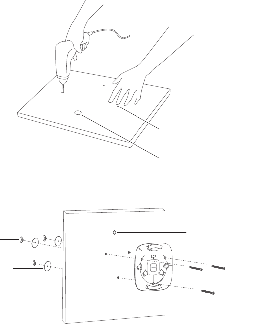
1. Remove the ceiling tile.
Remove the Ceiling Tile
2. Place the mounting bracket at the center of the ceiling tile. Mark the positions
of three mounting slots and the hole for Ethernet cable to feed through.
L≈40mm
L
Mark of the Hole for Ethernet
cable to feed through
Mark the Positions
06
3. Use a drill bit to drill three holes for screws, and drill a 10mm hole for the
Ethernet cable to feed through.
10mm hole for Ethernet cable feed
4mm hole for mounting bracket
Drill the Holes
4. Secure the mounting bracket to the ceiling board with nuts, washers and pan
head screws as shown below.
Hole to feed the Ethernet cable
Hole to feed the screw
Pan head screw
Nut
Washer
Secure the Mounting Bracket
07
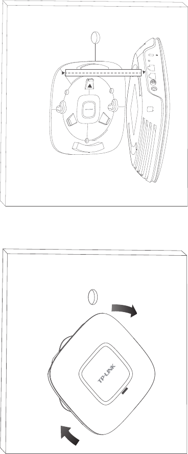
5. Align ARROW 1 with ARROW 2 as shown below, then press the EAP into the
mounting bracket.
RESET CONSOLE ETHERNET ON/OFF POWER
Align Two Arrows
6. Turn the EAP clockwise until it locks into place.
Make the EAP Lock into Place
08
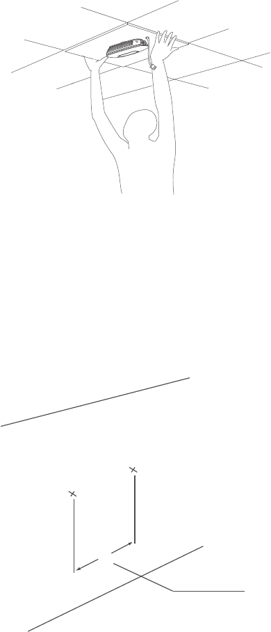
7. Feed the cable through the hole and set the ceiling tile back into place.
Fix the Ceiling Tile
8. Connect the Ethernet cable to the Ethernet port and ceiling mounting is done.
■Wall Mounting
There are two wall-mounting slots at the bottom of the EAP. To mount the EAP on
a wall, please follow the steps below.
1. Make two small pencil marks on the wall. The distance between the two marks
should be 98.6mm.
Wall
L
L=98.6mm
Mark on the Wall
09
2. Use a drill bit to drill two holes through the center of your marks. The diameter
of both holes should be 4mm.
Wall
4mm in diameter
Drill Two Holes
3. Insert the plastic extending tubes into the 4mm holes and drive the screws
into the tubes.
4. As Ceiling Mounting shows, press the EAP into the mounting bracket and
turn it clockwise until it locks into place.
5. Simply hang your EAP and the wall mounting is done.
4. Powering Mode
The EAP can be powered via a PSE device (e.g., a PoE switch) or a power adapter.
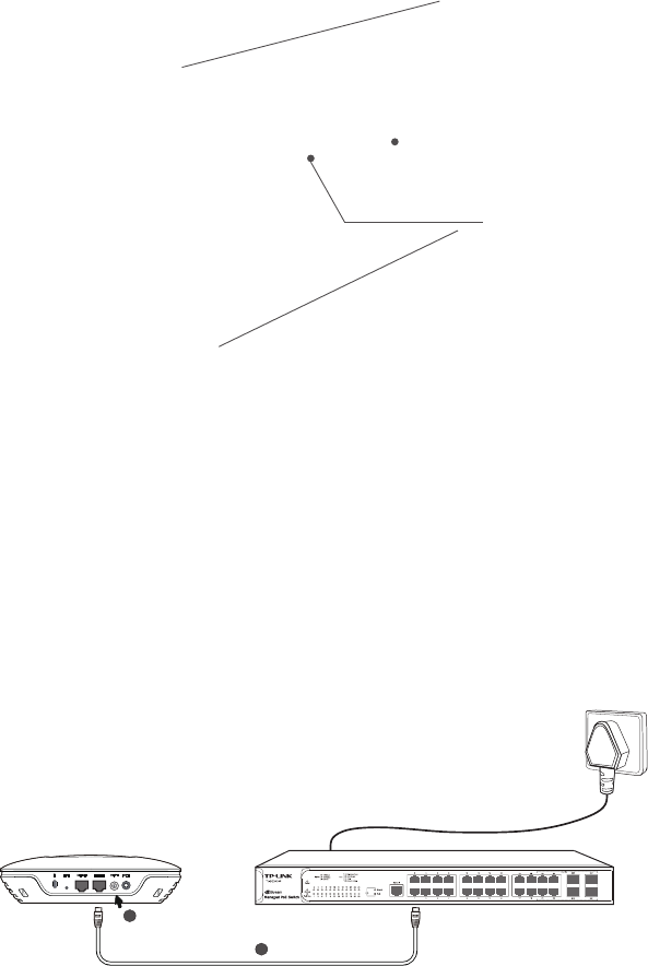
■Via PSE Device
EAP220 TL-SG3424P
2
1
Power the EAP via a PoE
10
1. Connect the EAP to a PSE device through an Ethernet cable.
2. Press the ON/OFF button on the interface panel of the EAP.
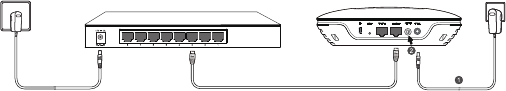
■Via Power Adapter
TL-SG2008
EAP220
Socket Socket
Power the EAP via a Power Adapter
1. Plug one end of the provided power adapter into the power jack of the EAP,
and the other end to a standard electrical wall socket.
2. Press the ON/OFF button on the interface panel of the EAP.
11
Getting Started with the EAP
How do you quickly build a wireless network with several EAPs? The following
content will instruct you on how to do network connection and software
configurations on EAPs. Management host can be connected to the EAPs wirelessly
or with wires. Wireless Login is recommended conveniently.
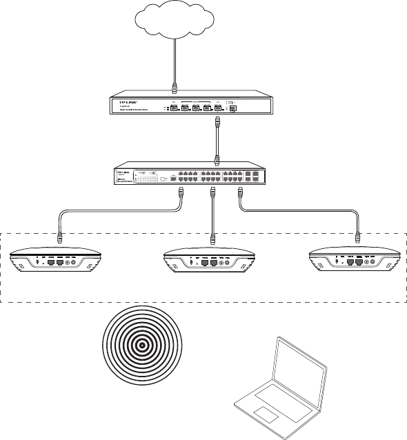
Option 1: Wireless Login
Router
Switch
Master EAP Slave EAP
Cluster
Management Host
Slave EAP
Internet
Sample Network Diagram for Wireless Login
Step 1: Power on
Power on the EAPs. The EAP with system initialization first completed will be
elected as the Master.
12
Step 2: Wireless Access
1. Make sure the management host is set to obtain IP address automatically.
2. Join the wireless network. The default SSID and password are shown below.
SSID: TP-LINK_2.4GHz_XXXXXX or TP-LINK_5GHz_XXXXXX for EAP220; TP-
LINK_2.4GHz_XXXXXX for EAP120. XXXXXX is the last 6 characters of EAP's
MAC address.
Password: Password is empty.
Step 3: Quick Setup
1. Open a web browser and type in http://tplinkeap.net to log in to the EAP.
The default user name and password are admin. In the Cluster mode, the
login will be directed to the Master EAP.
2. Create a new user name and password.
3. Follow instructions step by step to complete Quick Setup.
Congratulations! The above configurations on the Master EAP will be synchronized
to all the other EAPs automatically. Now you can enjoy the wireless network.
If you want to perform more configurations, please connect to the new SSID.
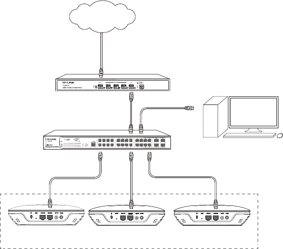
Option 2: Wired Login
Router
Switch
Master EAP Slave EAPSlave EAP
Cluster
Management Host
Internet
Sample Network Diagram for Wired Login
13
Step 1: Power on
Power on the EAPs. The EAP with system initialization first completed will be
elected as the Master.
Step 2: Wired Access
1. Make sure the management host is set to obtain IP address automatically.
2. Access your DHCP server and locate the IP address of the EAPs.
Step 3: Quick Setup
1. Open a web browser, in the address field type in any IP address of the EAPs
to log in the web server. The default user name and password are admin. In
the Cluster mode, the login will be directed to the Master EAP.
2. Create a new user name and password.
3. Follow instructions step by step to complete Quick Setup.
Congratulations! The above configurations on the Master EAP will be synchronized
to all the other EAPs automatically. Now you can enjoy the wireless network.
14
Q&A
Q1. Can Master EAP work as an access point?
Yes. In additon to managing and monitoring Slave EAPs, the Master EAP is
equipped with the features and functions of an AP, providing wireless access
to clients.
Q2. What is the maximum number of EAPs in a Cluster?
The maximum number of EAPs in a cluster is 24.
Q3. Can EAP120 be in the same Cluster with EAP220?
No, EAP120 and EAP220 cannot be in the same cluster. Only the EAPs of the
same model can be clustered together.
15
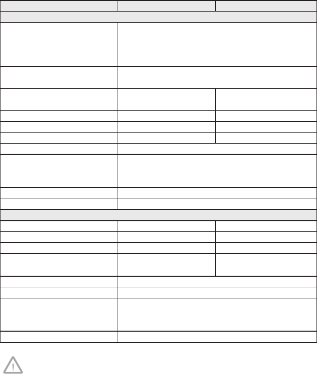
Specifications
Models EAP120 EAP220
HARDWARE FEATURES
Interface 10/100/1000Mbps Ethernet port (RJ-45)
Console port (RJ-45)
Power connector (DC-2)
Kensington lock slot
Buttons RESET
ON/OFF (for power supply)
Power Supply PoE or External 12VDC /
1A Power Supply
PoE or External 12VDC /
1.5A Power Supply
PoE Compatible 802.3af 802.3af
Maximum Power Consumption 4.4W 9.6W
Antenna 2*4dBi Embedded 4*4dBi Embedded
Mounting Ceiling/Wall mounting (Kits included)
Certication CE
FCC
RoHS
Operating Temperature 0℃~40℃ (32℉~104℉)
Operating Humidity 10%~90% non-condensing
WIRELESS FEATURES
Wireless Frequency 2.4GHz 2.4GHz & 5GHz
Wi-Fi Standard IEEE 802.11b/g/n IEEE 802.11a/b/g/n
Maximum Data Rate Up to 300Mbps Up to 600Mbps
Max RF Transmission Power(1) 23dBm 2.4GHz:23dBm
5GHz:20dBm
Multiple SSIDs Up to eight per radio
Captive Portal Authentication Support
Wireless Security WEP
WPA/WPA2-personal
WPA/WPA2-enterprise
Cluster Support, up to 24 APs in a cluster
Maximum transmission power may vary in different countries or regions.

16
Technical Support
■For more help, please go to: http://www.tp-link.com/en/support/faq
■To download the latest firmware, driver, utility and user guide, please go to:
http://www.tp-link.com/en/support/download
■For all other technical support, please contact us by using the following details:
Global Tel: +86 755 2650 4400
Fee: Depending on rate of different carriers, IDD.
E-mail: support@tp-link.com
Service time: 24hrs, 7 days a week
Australia/New Zealand Tel: AU 1300 87 5465 (Depending on 1300 policy.)
NZ 0800 87 5465 (Toll Free)
E-mail: support.au@tp-link.com (Australia)
support.nz@tp-link.com (New Zealand)
Service time: 24hrs, 7 days a week
Brazil Toll Free: 0800 608 9799 (Portuguese Service)
E-mail: suporte.br@tp-link.com
Service time: Monday to Saturday, 09:00 to 20:00; Saturday, 09:00 to 15:00
France Tel: 0820 800 860 (French service)
Fee: 0.118 EUR/min from France
Email: support.fr@tp-link.com
Service time: Monday to Friday 9:00 to 18:00 *Except French Bank holidays
Germany/Austria Tel: +49 1805 875 465 (German Service)
+49 1805 TPLINK
+49 820 820 360
Fee: Landline from Germany: 0.14EUR/min.
Landline from Austria: 0.20EUR/min.
E-mail: support.de@tp-link.com
Service time: Monday to Friday, 9:00 to 12:30 and 13:30 to 17:30. GMT+ 1
or GMT+ 2 (DST in Germany) *Except bank holidays in Hesse
Indonesia Tel: (+62) 021 6386 1936
Fee: Depending on rate of different carriers.
E-mail: support.id@tp-link.com
Service time: Monday to Friday 9:00 to 18:00 *Except public holidays
Italy Tel: +39 023 051 9020
Fee: Depending on rate of different carriers.
E-mail: support.it@tp-link.com
Service time: Monday to Friday, 9:00 to13:00 and 14:00 to 18:00
Malaysia Toll Free: 1300 88 875 465
Email: support.my@tp-link.com
Service time: 24hrs, 7 days a week
Poland Tel: +48 (0) 801 080 618
+48 223 606 363 (if calls from mobile phone)
Fee: Depending on rate of different carriers.
E-mail: support.pl@tp-link.com
Service time: Monday to Friday 9:00 to 17:00. GMT+1 or GMT+2 (DST)

17
Russian Federation Tel: 8 (499) 754 5560 (Moscow NO.)
8 (800) 250 5560 (Toll-free within RF)
E-mail: support.ru@tp-link.com
Service time: From 09:00 to 21:00 (Moscow time)
*Except weekends and holidays in RF
Singapore Tel: +65 6284 0493
Fee: Depending on rate of different carriers.
E-mail: support.sg@tp-link.com
Service time: 24hrs, 7 days a week
Switzerland Tel: +41 (0) 848 800 998 (German Service)
Fee: 4-8 Rp/min, depending on rate of different time.
E-mail: support.ch@tp-link.com
Service time: Monday to Friday, 9:00 to 12:30 and 13:30 to 17:30. GMT+ 1
or GMT+ 2 (DST)
Turkey Tel: 0850 7244 488 (Turkish Service)
Fee: Depending on rate of different carriers.
E-mail: support.tr@tp-link.com
Service time: 9:00 to 21:00, 7 days a week
UK Tel: +44 (0) 845 147 0017
Fee: Landline: 1p-10.5p/min, depending on the time of day.
Mobile: 15p-40p/min, depending on your mobile network.
E-mail: support.uk@tp-link.com
Service time: 24hrs, 7 days a week
Ukraine Tel: 0800 505 508
Fee: Free for Landline; Mobile: Depending on rate of different carriers.
E-mail: support.ua@tp-link.com
Service time: Monday to Friday 10:00 to 22:00
USA/Canada Toll Free: +1 866 225 8139
E-mail: support.usa@tp-link.com
Service time: 24hrs, 7 days a week

18
FCC STATEMENT
This equipment has been tested and found to comply with the limits for a Class A
digital device, pursuant to part 15 of the FCC Rules. These limits are designed to
provide reasonable protection against harmful interference when the equipment is
operated in a commercial environment. This equipment generates, uses, and can
radiate radio frequency energy and, if not installed and used in accordance with
the instruction manual, may cause harmful interference to radio communications.
Operation of this equipment in a residential area is likely to cause harmful
interference in which case the user will be required to correct the interference at
his own expense.
This device complies with part 15 of the FCC Rules. Operation is subject to the
following two conditions:
1) This device may not cause harmful interference.
2) This device must accept any interference received, including interference that
may cause undesired operation.
Any changes or modifications not expressly approved by the party responsible for
compliance could void the user’s authority to operate the equipment.
CE Mark Warning
or
This is a class A product. In a domestic environment, this product may cause radio
interference, in which case the user may be required to take adequate measures.
IC Statement
This Class A digital apparatus complies with Canadian ICES-003.
Cet appareil numérique de la classe A est conforme à la norme NMB-003 du
Canada.
Пр о дук т сертифікован о згідн о с прав и лами с ис т ем и Ук р С ЕПР О на
відповідність вимогам нормативних документів та вимогам, що передбачені
чинними законодавчими актами України.
FCC RF Radiation Exposure Statement:
This equipment complies with FCC RF radiation exposure limits set forth for an uncontrolled
environment. This device and its antenna must not be co-located or operating in conjunction
with any other antenna or transmitter.
“To comply with FCC RF exposure compliance requirements, this grant is applicable to only
Mobile Configurations. The antennas used for this transmitter must be installed to provide a
separation distance of at least 20 cm from all persons and must not be co-located or
operating in conjunction with any other antenna or transmitter.”

19
Safety Information
1) When product has power button, the power button is one of the way to shut
off the product; When there is no power button, the only way to completely
shut off power is to disconnect the product or the power adapter from the
power source.
2) Don’t disassemble the product, or make repairs yourself. You run the risk of
electric shock and voiding the limited warranty. If you need service, please
contact us.
3) Avoid water and wet locations.
NCC Notice & BSMI Notice
注意!
依據 低功率電波輻射性電機管理辦法
第十二條 經型式認證合格之低功率射頻電機,非經許可,公司、商號或使用者均不得擅自
變更頻率、加大功率或變更原設計之特性或功能。
第十四條 低功率射頻電機之使用不得影響飛航安全及干擾合法通行;經發現有干擾現象
時,應立即停用,並改善至無干擾時方得繼續使用。前項合法通信,指依電信規定作業之
無線電信。低功率射頻電機需忍受合法通信或工業、科學以及醫療用電波輻射性電機設
備之干 擾。
減 少 電 磁 波 影 響 ,請 妥 適 使 用 。
安全諮詢及注意事項
●請使用原裝電源供應器或只能按照本產品注明的電源類型使用本產品。
●清潔本產品之前請先拔掉電源線。請勿使用液體、噴霧清潔劑或濕布進行清潔。
●注意防潮,請勿將水或其他液體潑灑到本產品上。
●插槽與開口供通風使用,以確保本產品的操作可靠並防止過熱,請勿堵塞或覆蓋開口。
●請勿將本產品置放於靠近熱源的地方。除非有正常的通風,否則不可放在密閉位置中。
●請不要私自打開機殼,不要嘗試自行維修本產品,請由授權的專業人士進行此項工作。
此為甲類資訊技術設備,于居住環境中使用時,可能會造成射頻擾動,在此種情況下,使
用者會被要求採取某些適當的對策。
This product can be used in the following countries:
AT / BG / BY / CA / CZ / DE / DK / EE / ES / FI / FR / GB / GR / HU / IE / IT
LT / LV / MT / NL / NO / PL / PT / RO / RU / SE / SK / TR / UA / US

COPYRIGHT & TRADEMARKS
Specifications are subject to change without notice. is a registered
trademark of TP-LINK TECHNOLOGIES CO., LTD. Other brands and product names
are trademarks of their respective holders. No part of the specifications may be
reproduced in any form or by any means or used to make any derivative such
as translation, transformation, or adaptation without permission from TP-LINK
TECHNOLOGIES CO., LTD. Copyright © 2014 TP-LINK TECHNOLOGIES CO., LTD.
All rights reserved.
Website: http://www.tp-link.com
Tel: +86 755 26504400
E-mail: support@tp-link.com
7106505003 REV1.0.1