TP Link Technologies SC4171G Wireless Pan/Tilt Surveillance Camera User Manual TL SC4171 2
TP-Link Technologies Co., Ltd. Wireless Pan/Tilt Surveillance Camera TL SC4171 2
Contents
- 1. TL-SC4171_User Manual1
- 2. TL-SC4171_User Manual2
TL-SC4171_User Manual2
36
20.
r “frames per second”.
Quality: You can select the value of quality among Medium, Standard, Good, Detailed
able image quality for Fixed Quality or Fixed Bitrate, please refer to the
A. Frame-rate and Bitrate Table
¾ Image Size: Specify the image size when the network camera transmits. You can choose among
640 x 480, 320 x 240, and 160 x 1
¾ Frame Rate: Set the frame rate of the MJPEG image. You can choose values from 1, 2, 3, 4, 5, 7,
10, and 15 fps. The unit “fps” stands fo
¾ Quality:
z Auto: The quality will be automatically decided.
z Fixed
and Excellent.
)
Note:
Concerning how to select the suit
APPENDIX .
etwork to display the sub folders including Information, PPPoE, DDNS, UPnP,
tion, Wireless (for wireless models) and Messenger.
7.3 Network
Click the folder of N
Bonjour, IP Notifica
37
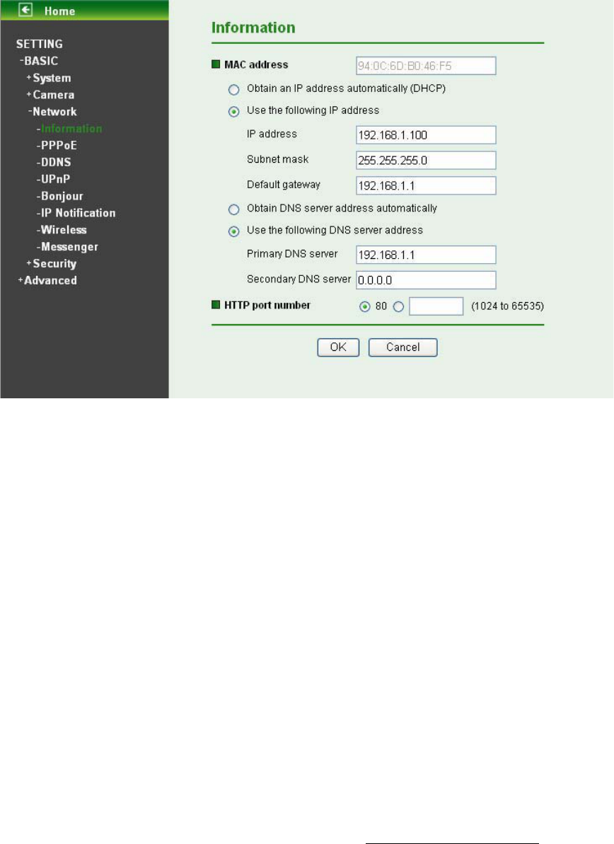
7.3.1 Information
The page of Information displays the MAC address of the device.
¾ Obtain an IP address automatically (DHCP): If a DHCP server is installed on the network, to
select this while the IP address is assigned by the DHCP server.
¾ Obtain DNS server address automatically: Select this to obtain the address of DNS server
automatically.
¾ Use the following IP address: Select this when the fixed IP address is set.
z IP address: Enter the IP address of the device.
z Subnet mask: Enter the subnet mask.
z Default gateway: Enter the default gateway.
¾ Use the following DNS server address: Select this when you set the fixed address as the IP
address of DNS server.
z Primary DNS server: Enter the IP address of the primary DNS server.
z Secondary DNS server: Enter the IP address of the secondary DNS server, if necessary.
¾ HTTP port number: Select 80 in general situations. If you want to use a port number other than 80,
select the text box and enter a port number between 1024 and 65535.
When you have set the HTTP port number to a number other than 80 on the Network setting page
or in the Setup Program, access the device by typing the IP address of the device on the web
browser as follows: for example, when HTTP port number is set to 2000 and the IP address of your
camera is set to 192.168.1.100, you should type in http://192.168.1.100:2000/ to access the device.
)
Note:
1. The IP Camera needs to be rebooted after it finishes changing the network setting completely.
Please go to “Setting
ė
Basic
ė
System
ė
Initialize” page and click the Reboot button after
you make some changes.
38
2. If you connect the IP Camera with your computer directly, the default network domain of camera is
192.168.1.xx.
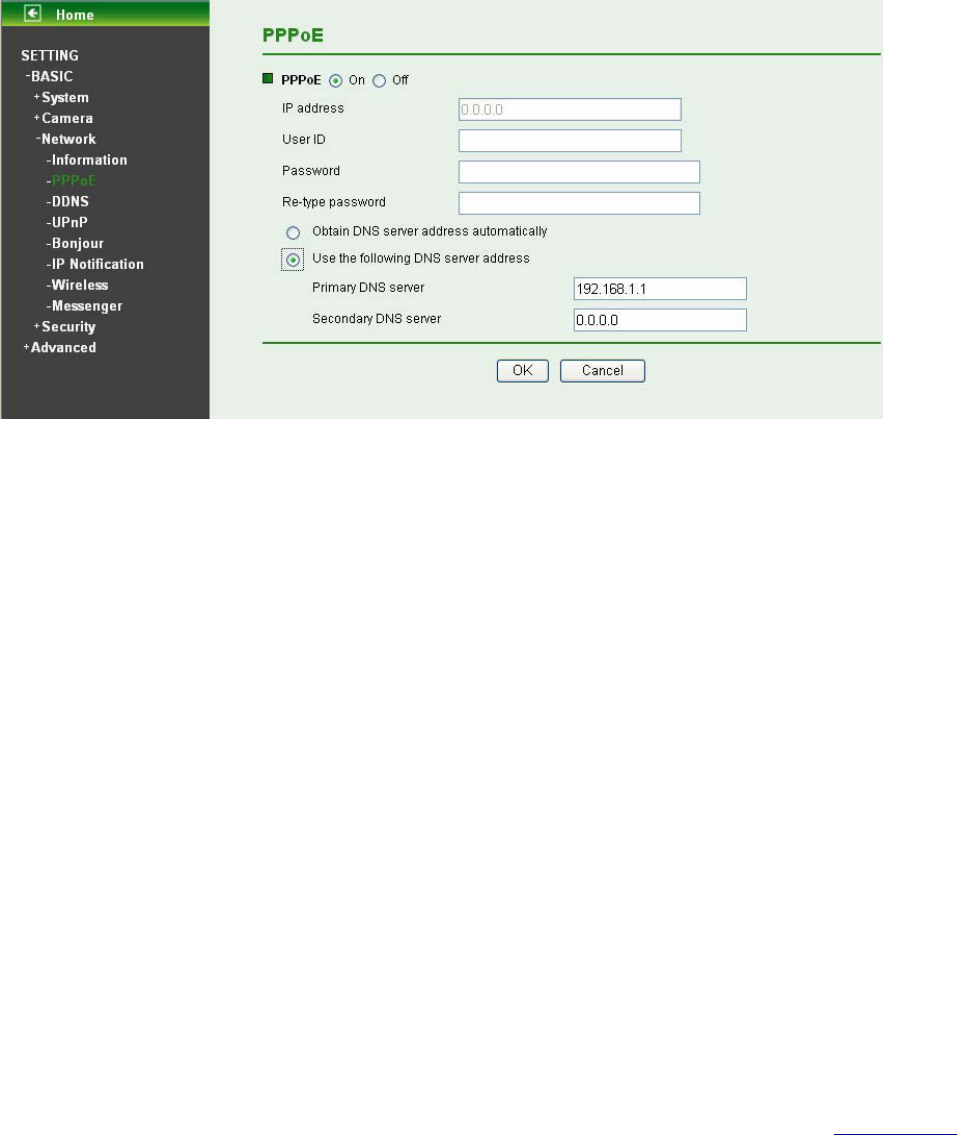
7.3.2 PPPoE (Point-to-Point Protocol over Ethernet)
If your ISP provides Dynamic IP with authentication by username and password, type all PPPoE
information in this part. When you use the PPPoE function, you need to turn on the DDNS or IP
Notification function at same time.
¾ IP Address: The IP address obtained at the PPPoE connecting with network.
¾ User ID: Enter the user ID for authentication necessary for PPPoE connections. Type it up to 64
characters.
¾ Password: Enter the password for authentication necessary for PPPoE connections. Type it up to
32 characters.
¾ Re-type Password: Re-type the password to confirm.
¾ Obtain DNS server address automatically: Select this to obtain the address of DNS server
automatically.
¾ Use the following DNS server address: Select this when you set the fixed address as the IP
address of DNS server.
z Primary DNS server: Enter the IP address of the primary DNS server.
z Secondary DNS server: Enter the IP address of the secondary DNS server.
)
Note:
1. PPPoE (Point-to-Point Protocol over Ethernet): PPPoE is a network protocol for encapsulating
Point-to-Point Protocol frames insider Ethernet frames. PPPoE connection is used mainly with
ADSL service where individual users connect to the ADSL transceiver (modem) over Ethernet work.
It also widely used in XDSL. (digital affiliate line such as ADSL, VDSL or SDSL)
2. The IP Camera needs to be rebooted after it finishes changing the network completely.
3. The IP Camera with Intelligent IP Installer can’t be found after PPPoE is active, but you can get the
IP address of the camera by IP Notification function. For more details, please refer to Section 7.3.6.
4. If the IP Notification function is not configured to report the IP address of the camera, you can reset
the camera to its factory default settings by pressing the Reset button. Then the camera can be
found by Intelligent IP Installer.
39
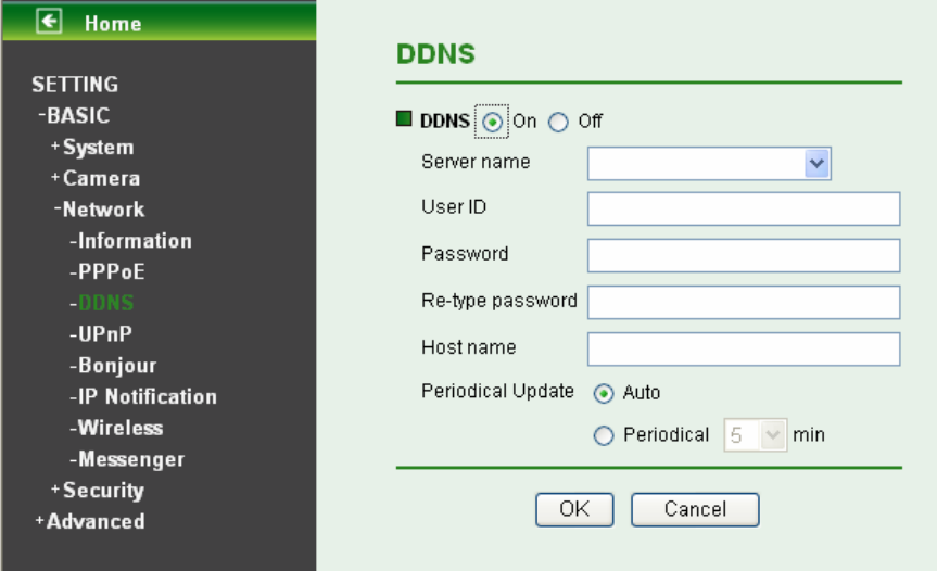
7.3.3 DDNS (Dynamic DNS)
DDNS is a system which allows the domain name data held in a name server to be updated in real time.
The most common use for DDNS is allowing an internet domain name to be assigned to a computer with
a varying/dynamic IP Address. This makes it possible for other sites on the internet to establish
connection to the machine without needing to track the IP Address themselves.
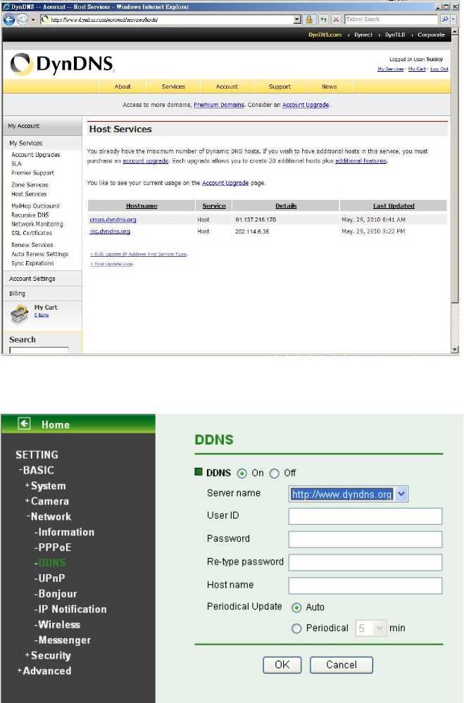
¾ Server name: Choose the DDNS Server from the list.
¾ User ID: Enter the user ID for authentication necessary for DDNS connections. Type it up to 64
characters.
¾ Password: Enter the password for authentication necessary for DDNS connections. Type it up to 32
characters.
¾ Re- type password: Re-type the password to confirm.
¾ Host name: Enter the host name that is registered to the DDNS server.
¾ Periodical Update:
z Auto: The domain name data will be updated automatically.
z Periodical: The domain name data will be updated once in a period. The period can be chosen
among 5, 10, 15, 30 and 60 minutes.
)
Note:
How to apply DDNS username and Host name? You can apply DDNS username and Host name by
the following steps:
40
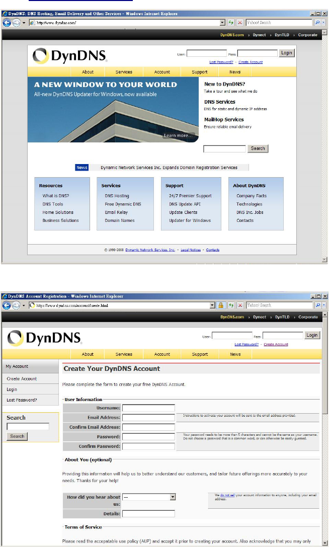
1. Login http://www.dyndns.org, click the Create Account.
2. Input all information and follow step by step with DynDNS.
41
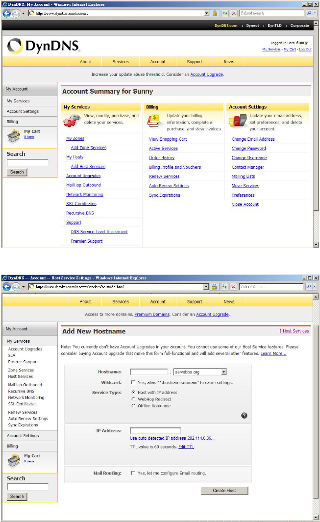
3. Login with new account and click Account ĺ My Hosts ĺ Add Host Services.
4. Type domain in the Hostname field and select sub-domain.
42
5. After type information, check your DDNS service.
6. Type your DDNS User ID, Password and Host name in Setting ĺ Network ĺ DDNS. After
completing setting, reboot IP Camera.
43
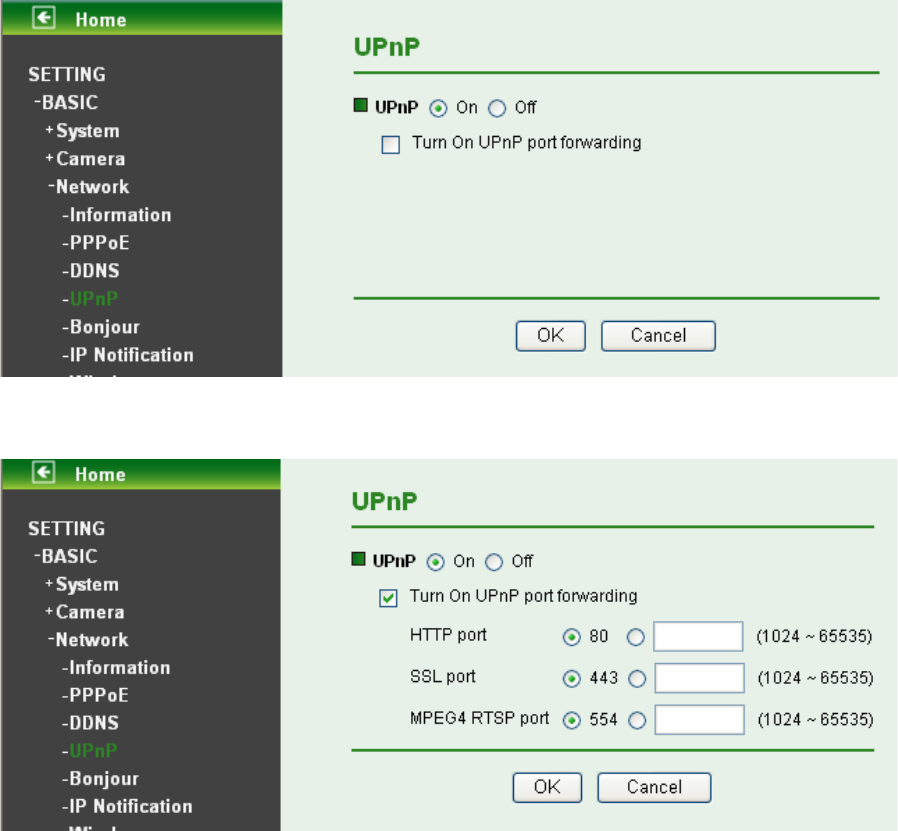
7.3.4 UPnP (Universal Plug and Play)
You can select UPnP function “On” or “Off”.
If a router is used to access to internet and it supports UPnP IGD function, please tick Turn On UPnP
port forwarding.
¾ HTTP port: The default HTTP port is 80. Or the port number can be entered, ranged from 1024 to
65535.
¾ SSL port: The default SSL port is 443. Or the port number can be entered, ranged from 1024 to
65535.
¾ MPEG4 RTSP port: The default MPEG-4 RTSP Port is 554. Or the port number can be entered,
ranged from 1024 to 65535.
)
Note:
UPnP (Universal Plug and Play): UPnP is a set of computer network protocol. It allows devices to
connect seamlessly and simplify the implementation of networks in the home and corporate
environments. The device supports UPnP which is enabled by default. The device will be automatically
detected and a new icon will be added to “My Network Place” if it also enables on your computer. It
provides Port Forwarding for opening a port in a router or firewall in a private network in order to let a
party from the outside world contact a inside user.
44
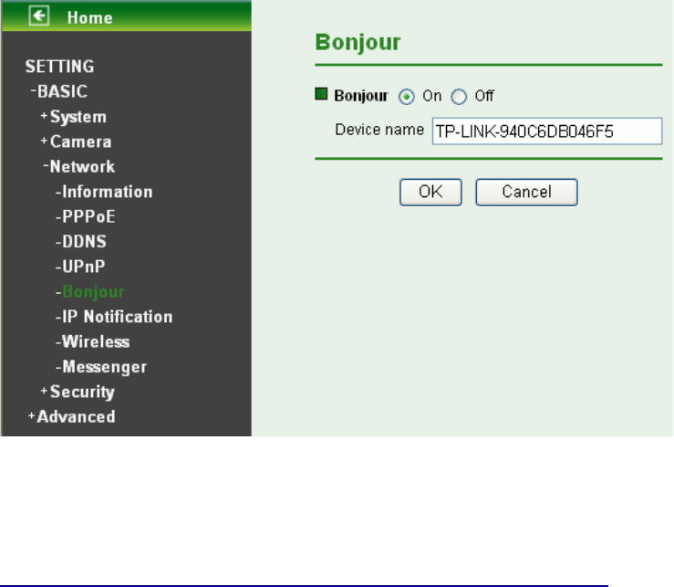
7.3.5 Bonjour
Bonjour, also known as zero-configuration networking, enables automatic discovery of computers,
devices, and services on IP networks. Bonjour uses industry standard IP protocols to allow devices to
automatically discover each other without the need to enter IP addresses or configure DNS servers.
¾ Device Name: Enter Device Name as you wish.
)
Note:
How to use Bonjour in your Windows Browser UI? Please check the link below:
http://www.apple.com/support/downloads/bonjourforwindows.html.
45
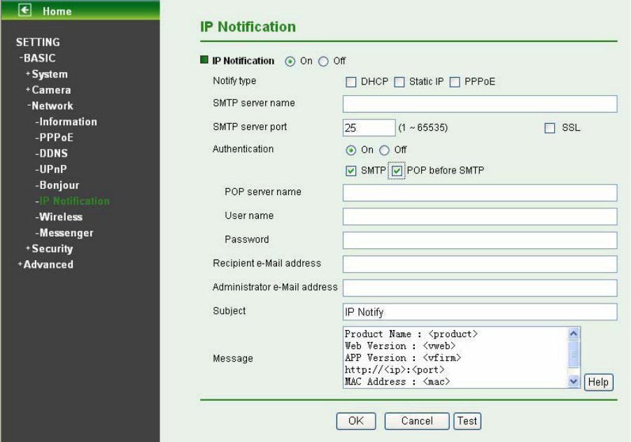
7.3.6 IP Notification
Once IP Notification is set to "On", the camera will automatically send an e-mail notification to tell users
its updated network parameters if the network settings about IP address, network connection type, HTTP
port or wireless connection is changed or completed. (Some settings will take effect after rebooting.)
¾ Notify Type: You can select the notify type among DHCP, Static IP, and PPPoE. When the network
settings related to the chosen notify type are changed, an e-mail notification will be sent to inform
you of the updated network information of the camera.
¾ SMTP Server Name: Type the SMTP server name up to 64 characters, or the IP address of the
SMTP server.
¾ SMTP Server Port: You can set port number from 1~65535 according to your mail server. The
default value is 25.
z SSL: Tick SSL box if the mail server you use has security restriction.
)
Note:
If you use g-mail as your mail server, you should set 587 as your port number and tick SSL box.
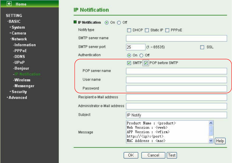
¾ Authentication: Select the authentication required when you send an email.
z Off: Select if no authentication is necessary when an email is sent.
z On: When authentication is necessary for sending an e-mail, there are three options SMPT,
POP before SMPT or both.
46
¾ SMTP: Select if SMTP authentication is necessary when an e-mail is sent.
¾ POP before SMTP: Select if POP before SMTP authentication is necessary when an e-mail is sent.
z POP server name: It is necessary when the POP before SMTP is selected in Authentication.
Type the POP (receiving mail) server name up to 64 characters, or type the IP address of the
POP server. This setting is necessary when the SMTP server which sends e-mails performs
authentication using the POP user account.
z User name, Password: Type the user name and Password of the user who has the mail
account. This setting is necessary when the SMTP server which sends e-mails performs
authentication.
¾ Recipient e-mail address: Type the recipient e-Mail address up to 64 characters. You can specify
up to three recipient E-mail addresses.
¾ Administrator e-mail address: Type the Administrator e-Mail address up to 64 characters. This
address is used for reply mail and sending system messages from the SMTP server.
¾ Subject: Type the subject/title of the e-Mail up to 64 characters. With respect to mail which is sent
according to the IP notification.
¾ Message: Type the text of the E-mail up to 384 characters. Default value provides network
information including IP, Port, MAC, Model, Firmware Version and Web Version.
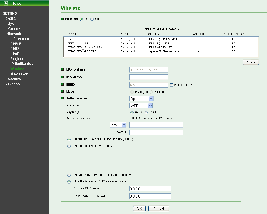
7.3.7 Wireless
The wireless network has to be set up by using cable network connection. After setting the camera
correctly, the wireless function can work with cable network connection. Wireless settings must be the
same as the access point or ad-hoc device. When changing the settings they should always be made
first in the camera and then in the wireless access point. This ensures that the camera is always
accessible when making changes.
47
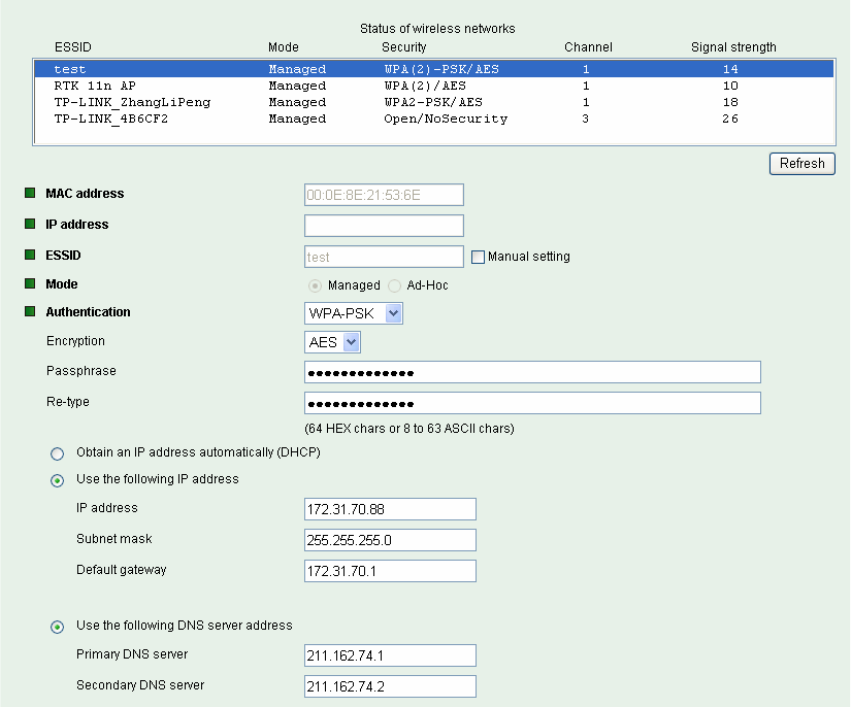
¾ Status of Wireless Networks
The list above is the result of network scan. The network currently linked to will be shown in blue. The
following information is provided.
z ESSID - The name of a wireless network (or ad-hoc device). If the same name occurs several
times this means that several access points for that network were found. The camera cannot be
configured to only associate with one particular access point.
z Mode - Shows if the network type is Managed (access point or router) or Ad-Hoc (another
client).
z Security - Shows which type of security the network uses. See below for the security types
supported by the camera.
z Channel - Shows the wireless channel currently in use.
z Signal strength - Shows the signal strength.
z Refresh: Click the Refresh button to rescan the existing wireless networks in the local area.
¾ Wireless Setting
These settings control how the camera is connected to the wireless network.
z MAC address – This displays the MAC address of the IP camera.
z IP address – The IP address field is not for entering, but for displaying. It displays blank,
0.0.0.0 or an IP Address. When it is blank, the camera doesn’t establish physical link with
access point. The 0.0.0.0 means that physical link is established, and that IP camera is trying to
get the IP address. When it displays an IP address, users can use wireless network.
48
z ESSID (ESSID is sometimes written as SSID) - This is the name of the wireless network to
which the camera is ready to connect. The field accepts up to 32 alphanumeric characters. The
name must be exactly the same as that used in the wireless access point; otherwise, the
connection will not be established.
Leaving this field blank means the camera will attempt to access the nearest unsecured
network. There are two methods to enter the ESSID field.
9 Method 1: Click the desired wireless network in the network list above, then the field will
display the ESSID of that network.
9 Method 2: Tick the box “Manual Setting” behind the field, then ESSID can be entered.
z Mode – The Managed option means the camera will attempt to connect to an access point. The
Ad-hoc option allows the camera to connect to other wireless device clients.
z Authentication – The authentication of the wireless network. All the parameters for
authentication must be the same as that of the desired AP or Router. 64/128-bit WEP,
WPA-PSK and WPA2-PSK encryption security are supported by the camera. Click the desired
wireless network in the network list above, the corresponding option will be selected as same
as that of the desired AP or Router automatically. Here we select the first item in the network list
above for example to introduce how to join in a wireless network.
Select the first item, the figure will display as shown below:
9 Encryption – Keep this option the same with that of network test.
9 Passphrase - Enter the desired AP/ Router’s password here.
9 Re-type – Enter the password above again to affirm it.
49
9 Obtain an IP address automatically (DHCP) – If a DHCP server is installed on the
network, to select this while the IP address is assigned by the DHCP server.
9 Use the following IP address - Select this when the fixed IP address is set.
IP address: Enter the IP address of the camera, which must be in the same subnet
with that of the desired AP/ Router.
Subnet mask: Enter the subnet mask.
Default gateway: Enter the default gateway.
9 Obtain DNS server address automatically - If you select Obtain an IP address
automatically (DHCP) above, this entry will display in the figure. Select this to obtain the
address of DNS server automatically.
9 Use the following DNS server address - Select this when you set the fixed address as
the IP address of DNS server.
Primary DNS server: Enter the IP address of the primary DNS server.
Secondary DNS server: Enter the IP address of the secondary DNS server, if
necessary.
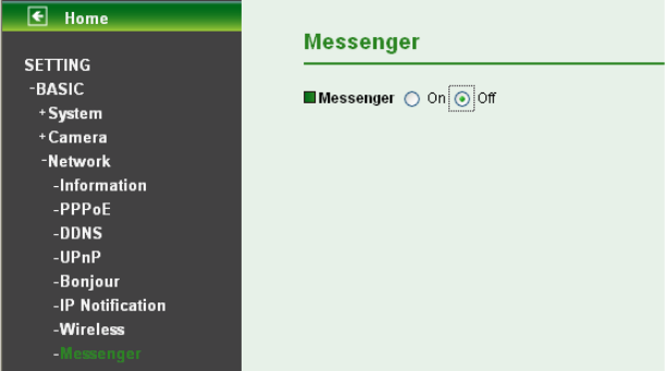
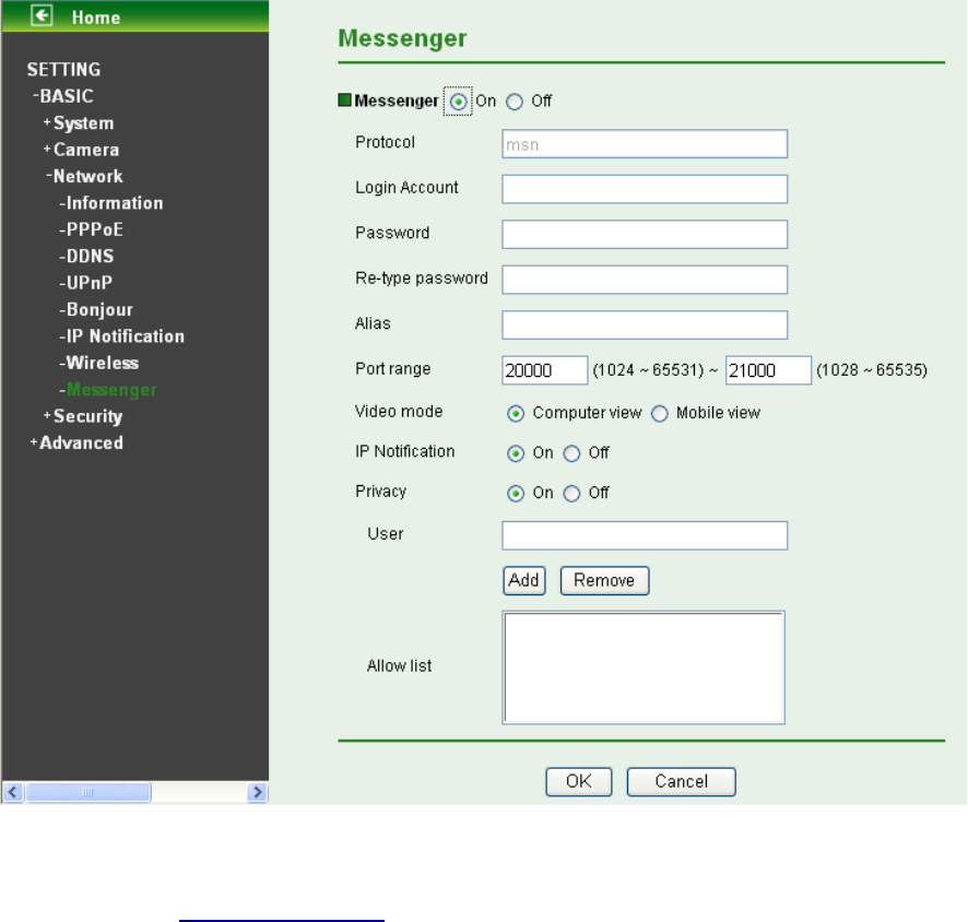
7.3.8 Messenger
If Messenger option is selected On, you can set out the setting of MSN account.
Messenger function provides an easy-connect feature. User can easily know what the camera’s private
and public IP addresses are.
50
¾ Protocol: support MSN only.
¾ Login Account: Camera will use this account to login MSN server. This MSN account should be
applied form http://www.msn.com.
¾ Password: password for this msn account.
¾ Re-type password: re-type password to double confirm.
¾ Alias: This alias will display on MSN like the following which display in red frame.
¾ Port range: Camera will select one port from this port range for video transmission.
¾ Video Mode: You can select Computer View or Mobile View.
z Computer View: This mode is the default value.
z Mobile View: If Messenger function doesn’t work due to the firewall or the function limit of
router, please choose Mobile View.
¾ IP Notification: Switch the IP notification On/Off. If this feature switches On, camera will send IP
notification to the users who are allowed.
¾ Privacy: Switch privacy On/Off. When privacy turns on, only those users in allow list can access the
camera.
¾ User: Input to this blank to edit allow list.
¾ Allow list: When privacy turns on, only those users in allow list can access the camera.
51
7.4 Security
Click the folder of Security to display the sub folders including Account and HTTPS.
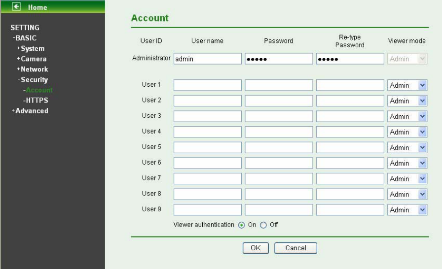
7.4.1 Account
The device fault account and password setting is “admin / admin”. That means everyone who knows IP
address can access the device including all configuration. It is necessary to assign a password if the
device is intended to be accessed by others.
¾ User name: Set a user name between 4-16 characters.
¾ Password: Set a password between 4-16 characters.
¾ Re-type Password: Re-type the password to confirm.
¾ Viewer Mode: Set the user mode among Admin, Operator, and Viewer. Different viewer mode has
different limits of authority.
z The Admin mode has all authority of configuration.
z The Operator mode can not only view the Live View but also control the PTZ (apply in speed
dome).
z The Viewer mode only can view the Live View.
¾ Viewer Authentication: Select whether the authentication is needed when users access to live
view.
z On: Authentication is required to let different users have different levels of permission to access
the camera view.
z Off: Authentication is not required to access the camera. Click Off and select one (among
Admin, Operator and Viewer) from the pull list as default, then all users can view directly the
video with the default permission without entering username and password.
*If you want to have a higher authority than default, you can key in appropriate username and
password in the diag box that pop up when performing advanced operations that are only allowed
by the higher authority.
52
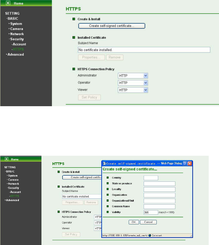
7.4.2 HTTPS
HTTPS is a URI scheme used to indicate a secure HTTP connection. It is syntactically identical to the
http:// scheme normally used for accessing resources using HTTP. Use an https: //URL/ with a different
default TCP port (443) and an additional encryption / authentication layer between the HTTP and TCP,
you can use the IP camera through HTTPS easily by using https:// instead of http://.
¾ Create & Install: Create a self-signed certificate for HTTPS to recognize.
¾ Installed Certificate: Display or remove the properties of the installed certificate.
¾ HTTPS Connection Policy: Set HTTPS connection policy for different level of users.
To use the HTTPS encryption, please set up “Create self-signed certificate” for the first time you
use the HTTPS function, and then set up the connection policy for different users.
)
Note:
When enable HTTPS with RTSP on mode, the IP Camera only protect the setting such as username and
password and do not protect video and audio. When enable HTTPS with RTSP off mode, the IP Camera
will protect all setting including video and audio.
53
Chapter 8 Setting-Advanced
Click the folder of Advanced to display the sub folders including PT Control, Present Position, Patrol,
FTP client, SMTP, HTTP Event, Alarm Output, Schedule, Alarm Input, Alarm Buffer, Motion
detection and System Log.
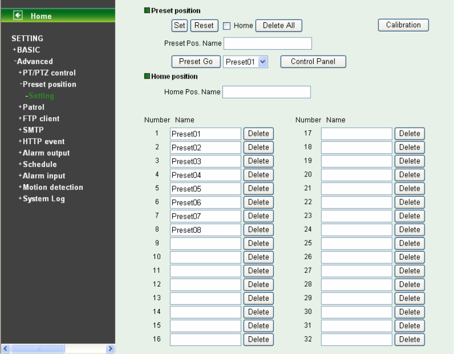
8.1 PT/PTZ Control
In this section, it provides Pan, Tilt, Auto Pan speed control setting.
¾ Pan speed: Specify the moving speed of the left and right commands. Available options are from 0
(slowest) to 100 (fastest). The larger the value, the faster the speed.
¾ Tilt speed: Specify the moving speed of the up and down commands. Available options are from 0
(slowest) to 100 (fastest). The larger the value, the faster the speed.
¾ Auto Pan speed: Specify the moving speed of the patrol tour. Available options are from 0 (slowest)
to 100 (fastest). The larger the value, the faster the speed.
54
8.2 Preset Position
¾ Set: Use it to save the camera position to a preset number. Carry out the following steps.
z Move the camera to the position to be saved while you are checking the image with the main
console.
z Write the preset position name in “Preset Pos. Name text” box.
z Click the Set. The camera position is saved.
z If want to set this position as home position, click Home option on. Click the Set. The camera
position is saved as home position.
)
Note:
Setting the new Home position will replace previous Home position.
¾ Reset: When writing the preset position name in Preset Pos. Name text box, press Reset to clean
filed words.
¾ Delete All: Be careful! When pressing Delete All, all Preset Position information will be deleted.
¾ Calibration: Click it and the camera will move to the straight ahead position.
¾ Preset Go: Choose one preset position, click the button, and then the camera will be set to the
selected preset position. This button allows users to adjust the camera position more conveniently
and efficiently.
¾ Control panel: Click Control panel button and the control panel will appear. The camera position
can be adjusted by clicking the direction buttons.
55
¾ Delete: Select a preset number from 1 to 32 in the list box. Use it to delete a specific preset position
setting.
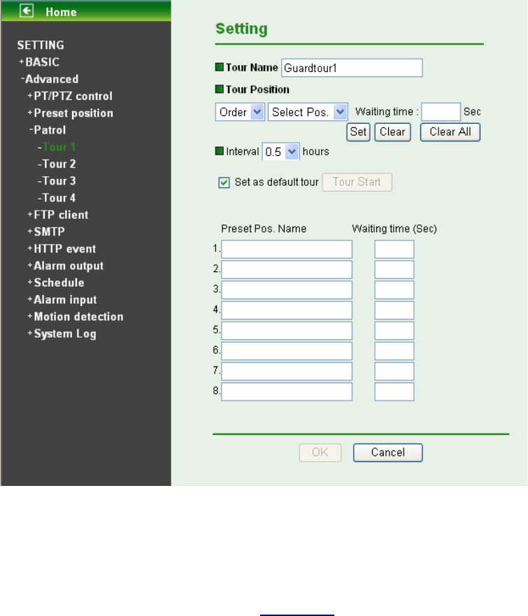
8.3 Patrol
There are four patrol tours to set for composing different preset positions. Each one lists up to 8 positions
which can be programmed, and the camera moves to the programmed positions sequentially. The
camera stops when it moves to the last preset position.
¾ Tour name: Rename the tour name.
¾ Tour position
z Order: There are 8 orders to select for camera directions.
z Select Pos.: There are preset positions to choose for each order. (For more information about
preset position, please refer to Section 8.2.)
z Waiting time: Define how long the camera is needed to stop at this position. The range is 1~99
seconds.
z Set: Click it to save the camera position to a preset number.
z Clear: If a preset position is not needed, select the tour order and click Clear to delete this
position information.
z Clear All: Be careful! When you click Clear All, it will clear out all information of this tour.
¾ Interval: Define the cycle interval between two patrol tours. The interval value is among 0.5, 1, 2, 4,
8, 12 and 24 hours.
¾ Set as default tour: Tick it to set this tour as default.
56
z Tour Start: To click Tour Start, and then the camera will start the preset patrol tour.
z Tour Stop: While the camera moves on patrol tour, click Tour Stop to stop the patrol tour.
¾ Carry out the following steps:
1. Click Order and choose one of eight orders.
2. Click Select Pos. and choose one of the preset positions.
3. Fill in the Waiting time.
4. Click Set, and then the tour position is saved.
5. Follow the steps to set the other orders.
6. Click the OK to save the tour.
8.4 FTP Client
This menu is used for capturing and sending images to an FTP server. By using FTP client function, you
can send to FTP server the image file which has been shot and recorded linked with the built-in motion
detection function. Click the folder of FTP client to display the sub folders including General, Alarm
sending and Periodical sending.
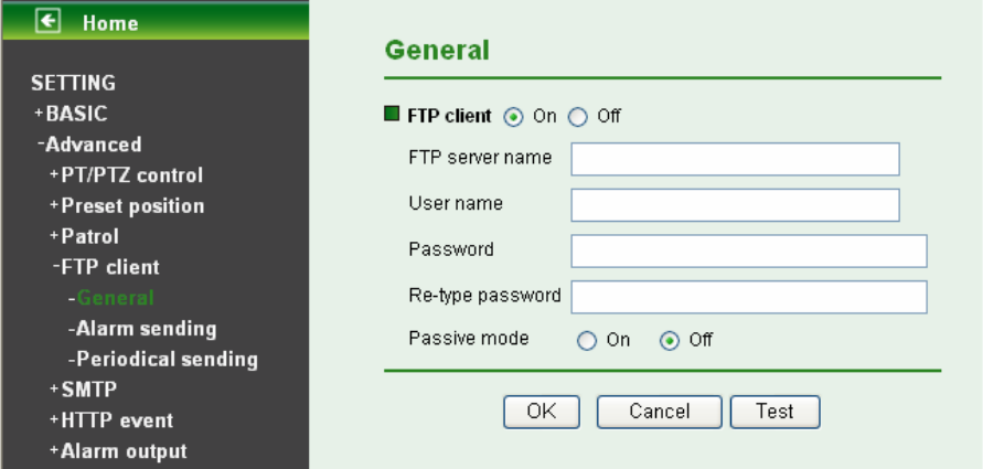
8.4.1 General
Select “On” when you use FTP function. The FTP client setting page appears.
Select “Off”, when you do not use the FTP client function.
)
Note:
The frame rate and operability on the main viewer may decrease while a file is being transmitted by the
FTP client function.
¾ FTP server name: Type the FTP server name to upload still images up to 64 characters, or the IP
address of the FTP server.
¾ User name: Type the user name for the FTP server.
¾ Password: Type the password for the FTP server.
¾ Re-type password: To confirm the password, type the same characters as you typed in the
Password box.
57
¾ Passive mode: Set whether you use the passive mode of FTP server or not when connecting to
FTP server. Select On to connect to FTP server using the passive mode.
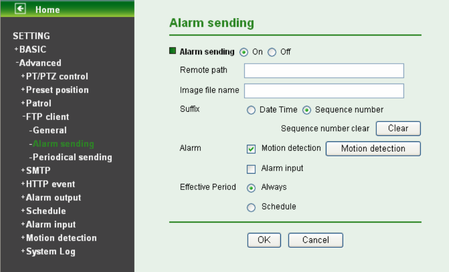
8.4.2 Alarm Sending
Set to forward the image file to the specified FTP server linked with the alarm detection by the built-in
motion detection function. Select On to send the image file to FTP server linked with the alarm detection.
¾ Remote Path: Type the path to the destination in FTP server up to 64 characters.
¾ Image File Name: Type the file name you want to assign to the images when sending to the FTP
server. You can use up to 10 alphanumeric characters, - (hyphen) and _ (underscore) for naming.
¾ Suffix: Select a suffix to add to the file name
z Date & time: The date & time suffix is added to the Image file name. The date/time suffix
consists of lower two-digits of year (2 digits), month (2 digits), date (2 digits), hour (2 digits),
minute (2 digits), second (2 digits), and consecutive number (2 digits), thus 14-digit number is
added to the file name.
z Sequence number: A consecutive number of 10 digits between 0000000001 and 4294967295
and two fixed digits 00 are added to the Image file name.
z Sequence number clear: Click Clear and the suffix of the sequence number returns to 1.
¾ Alarm
z Motion Detection: Click it on for using Motion Detection function as a sensor. You can set
motion detection function at the motion detection function page.
58
)
Note:
You can set motion detection at motion detection page. (Please go to “Setting ĺ Advanced
ĺMotion Detection ĺ Setting”. For more details, please refer to Section 8.10.)
z Alarm Input: Select the connected alarm.
9 Alarm input1: The external sensor which is connected to Alarm input1 of the alarm input.
59
)
Note:
You can set the alarm input function at Alarm Input page. (Please go to “Setting ĺ Advanced ĺ
Alarm Input ĺ Setting”. For more details, please refer to Section 8.9.)
¾ Effective period: Set the period when the periodical sending is effective.
z Always: The periodical sending is always effective.
z Schedule: You can specify the period when the periodical sending is effective in the Schedule
setting in the other section.
)
Note:
You can set schedule function at Schedule page. (Please go to “Setting ĺ Advanced ĺ
Schedule ĺ Setting”. For more details, please refer to Section 8.8.)
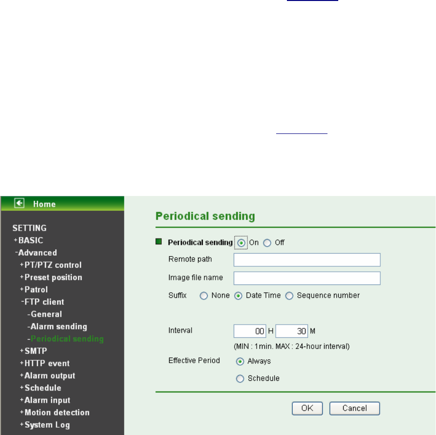
8.4.3 Periodical Sending
You can set to send an image file to FTP server periodically by selecting On to send the image file to
FTP server linked with setting period.
¾ Remote path: Type the path to the destination in FTP server up to 64 characters.
¾ Image file name: Type the file name of the image sent by SMTP up to 10 alphanumeric characters,
- (hyphen) and _ (under score).
¾ Suffix: Select a suffix to be added to the file name sent by SMTP.
z None: The name of the sent file will be the Image file name.
z Date & time: The date & time suffix is added to the Image file name. The date & time suffix
consists of lower two-digits of year (2 digits), month (2 digits), date (2 digits), hour (2 digits),
minute (2 digits) and second (2 digits), and consecutive number (2 digits), thus 14-digit number
is added to the file name.
z Sequence number: A consecutive number is added to the Image file name.
z Sequence number clear: Click Clear and the suffix of the sequence number returns to 1.
¾ Interval: Set the time interval of the periodical sending. Min value is 1 min and Max value is 24 hour.
60
¾ Effective period: Set the period when the periodical sending is effective.
z Always: The periodical sending is always effective.
z Schedule: You can specify the period when the periodical sending is effective in the Schedule
setting in the other section.
)
Note:
You can set schedule function at schedule page. (Please go to “Setting ĺ Advanced ĺ Schedule
ĺ Setting”. For more details, please refer to Section 8.8.)
8.5 SMTP
SMTP is used for sending an image via e-mail. By using Mail (SMTP) function, you can send a mail with
attached image file which has been shot linked with the external sensor input or with the built-in motion
detection function. The image file can also be sent periodically. Click the folder of SMTP to display the
sub folders including General, Alarm sending and Periodical sending.
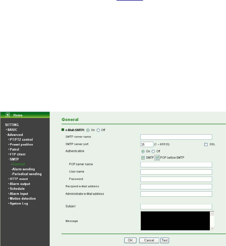
8.5.1 General
Select On when you use the SMTP function. The common setting options are displayed below. Select
Off, if you do not wish to use the e-Mail (SMTP) function.
)
Note:
The setting of General will be the same as the setting of IP Notification. (Please check “Setting ĺ
Basic ĺ Network ĺ IP Notification”.)
¾ SMTP server name: Type the SMTP server name up to 64 characters, or the IP address of the
SMTP server.
¾ SMTP Server Port: You can set port number from 1~65535 according to your mail server. The
default value is 25.
z SSL: Tick SSL box if the mail server you use has security restriction.
61
)
Note:
If you use g-mail as your mail server, you should set 587 as your port number and tick SSL box.
¾ Authentication:
z Off: No authentication is necessary when an email is sent.
z On: Authentication is necessary when an e-mail is sent. To set the authentication, please select
one from SMTP and POP before SMTP.
¾ SMTP: Select it if SMTP authentication is necessary when an e-mail is sent.
¾ POP before SMTP: Select it if POP before SMTP authentication is necessary when an e-mail is
sent.
)
Note:
When authentication is set to On, be sure to select either SMTP or POP before SMTP, or both of
them.
z POP server name: It is necessary when the POP before SMTP is selected in Authentication.
Type the POP (receiving mail) server name up to 64 characters, or type the IP address of the
POP server. This setting is necessary when the SMTP server which sends e-mails performs
authentication using the POP user account.
z User name, Password: Type the User name and Password of the user’s mail account. This
setting is necessary when the SMTP server which sends e-mails performs authentication.
¾ Recipient e-mail address: Type the recipient e-Mail address up to 64 characters. You can specify
up to three recipient E-mail addresses.
¾ Administrator e-mail address: Type the Administrator e-Mail address up to 64 characters. This
address is used for reply mail and sending system messages from the SMTP server.
¾ Subject: Type the subject/title of the e-Mail up to 64 characters. With respect to mail which is sent
according to the alarm detection when Alarm sending of the alarm tab is set to On, the characters
standing for the sensor type added to the subject.
¾ Message: Type the text of the E-mail up to 384 characters. (A line break is equivalent to 2
characters.)
62
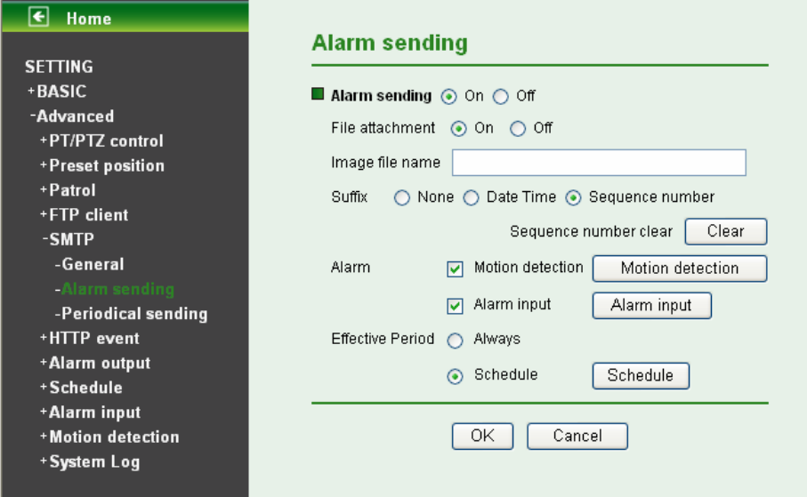
8.5.2 Alarm Sending
Set to send the mail with connection to the alarm detection by the built-in motion detection function.
Select On to send the image file to SMTP server linked with the alarm detection.
¾ Alarm sending: Select On to set to send mail with connection to the alarm detection.
¾ File attachment: Set whether an image file is attached to the mail sent or not. When On is selected,
the image file made by the settings below is attached. When Off is selected, only the message is
sent.
¾ Image file name: Type the file name you want to assign to the image to attach a mail. You can use
up to 10 alphanumeric, - (hyphen) and _ (underscore) for naming.
¾ Suffix: Select a suffix to add to the file name.
z Date & time: The date & time suffix is added to the Image file name. The date/time suffix
consists of lower two-digits of year (2 digits), month (2 digits), date (2 digits), hour (2 digits),
minute (2 digits), second (2 digits), and consecutive number (2 digits), thus 14-digit number is
added to the file name.
z Sequence number: A consecutive number of 10 digits between 0000000001 and 4294967295
and two fixed digits 00 are added to the Image file name.
z Sequence number clear: Click Clear and the suffix of the sequence number returns to 1.
¾ Alarm
z Motion Detection: Click it on for using Motion Detection function as a sensor. You can set
motion detection function at the motion detection function page.
63
)
Note:
You can set motion detection at motion detection page. (Please go to “Setting ĺ Advanced
ĺMotion Detection ĺ Setting”. For more details, please refer to Section 8.10.)
z Alarm Input: Select the connected alarm.
9 Alarm input1: The external sensor which is connected to Alarm input1 of the alarm input.
64
)
Note:
You can set the alarm input function at Alarm Input page. (Please go to “Setting ĺ Advanced ĺ
Alarm Input ĺ Setting”. For more details, please refer to Section 8.9.)
¾ Effective period: Set the period when the periodical sending is effective.
z Always: The periodical sending is always effective.
z Schedule: You can specify the period when the periodical sending is effective in the Schedule
setting in the other section.
)
Note:
You can set schedule function at Schedule page. (Please go to “Setting ĺ Advanced ĺ
Schedule ĺ Setting”. For more details, please refer to Section 8.8.)
8.5.3 Periodical Sending
You can set to send an image file by SMTP server periodically by selecting On to send the image file by
SMTP server linked with setting period.
¾ Image file name: Type the file name of the image sent by SMTP up to 10 alphanumeric characters,
- (hyphen) and _ (under score).
¾ Suffix: Select a suffix to be added to the file name sent by SMTP.
z None: The name of the sent file will be the Image file name.
z Date & time: The date & time suffix is added to the Image file name. The date & time suffix
consists of lower two-digits of year (2 digits), month (2 digits), date (2 digits), hour (2 digits),
minute (2 digits) and second (2 digits), and consecutive number (2 digits), thus 14-digit number
is added to the file name.
z Sequence number: A consecutive number is added to the Image file name.
z Sequence number clear: Click Clear and the suffix of the sequence number returns to 1.
65
¾ Interval: Set the time interval of the periodical sending. Min value is 30 min and Max value is 24
hour.
¾ Effective period: Set the period when the periodical sending is effective.
z Always: The periodical sending is always effective.
z Schedule: You can specify the period when the periodical sending is effective in the schedule
setting in the other section. Please check “Setting ĺ Basic ĺ Advance ĺ Schedule ĺ
Setting.”
)
Note:
You can set schedule function at schedule page. (Please go to “Setting ĺ Advanced ĺ Schedule
ĺ Setting”. For more details, please refer to Section 8.8.)
8.6 HTTP Event
HTTP Event is used for sending commands to an HTTP server. By using HTTP client function, you can
send the command defined by yourself, linked with the external sensor input or with the built-in motion
detection function to HTTP server. HTTP Event setting menu is composed of two tabs, General and
Alarm sending. Click the folder of HTTP Event to display the sub folders including General and Alarm
sending.
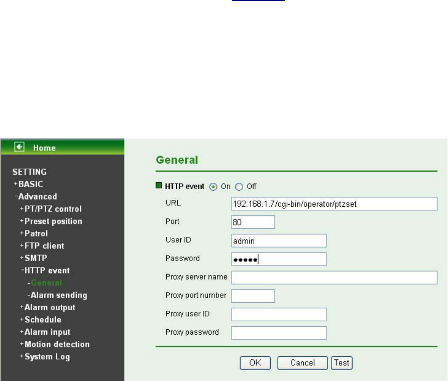
8.6.1 General
Select On, and you can start setting up the function.
HTTP Event: Set up the HTTP server URL, port, User ID, Password, and Proxy server settings.
For example:
URL: 192.168.1.7/cgi-bin/operator/ptzset
)
Note:
The setting of URL should be the same as CGI.
66
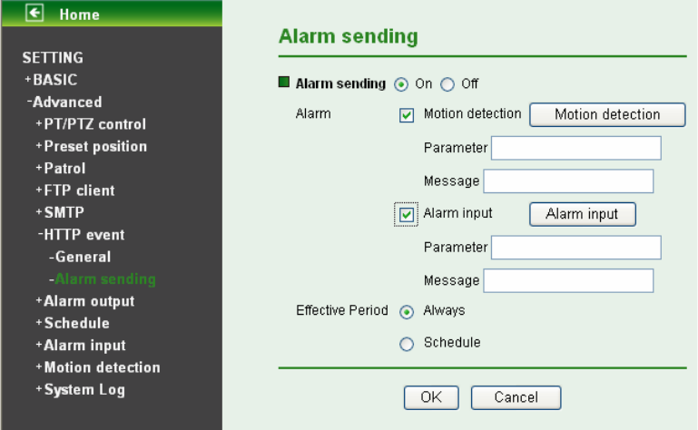
8.6.2 Alarm Sending
Set to send the commands via the alarm detection, external sensor input or built-in motion detection
function. Select On to send the commands to HTTP server linked with the alarm detection.
¾ Alarm sending: Select On to set to send command with connection to the alarm detection.
¾ Alarm
z Motion Detection: Click it on for using Motion Detection function as a sensor. You can set
motion detection function at the motion detection function page.
67
)
Note:
1. You can set motion detection at motion detection page. (Please go to “Setting ĺ Advanced
ĺMotion Detection ĺ Setting”. For more details, please refer to Section 8.10.)
2. Motion Detection works only when the MPEG4 function is On.
9 Parameter: the parameter of CGI (defined in URL of HTTP ĺ General) is from your target
device. For example, move=down.
68
9 Message: message will show up in the form of Message = PTZ down. If your target device
didn’t support the parameter of message, you can’t see the message. So you can just take
the message as a note. For example: PTZ down.
z Alarm Input: Select the connected alarm.
9 Alarm input1: The external sensor which is connected to sensor input1 of the alarm input.
)
Note:
You can set the alarm input function at Alarm Input page. (Please go to “Setting ĺ Advanced ĺ
Alarm Input ĺ Setting”. For more details, please refer to Section 8.9.)
9 Parameter: the parameter of CGI (defined in URL of HTTPĺGeneral) is from your target
device. For example, move=down.
9 Message: message will show up in the form of Message = PTZ down. If your target device
didn’t support the parameter of message, you can’t see the message. So you can just take
the message as a note. For example: PTZ down.
¾ Effective period: Set the period when the periodical sending is effective.
z Always: The periodical sending is always effective.
z Schedule: You can specify the period when the periodical sending is effective in the Schedule
setting in the other section.
69
)
Note:
You can set schedule function at Schedule page. (Please go to “Setting ĺ Advanced ĺ
Schedule ĺ Setting”. For more details, please refer to Section 8.8.)
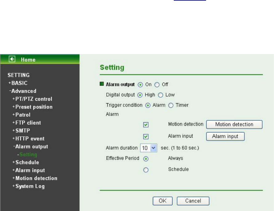
8.7 Alarm Output
When you click Alarm output on the setting-advanced menu, the Setting menu appears. You can set in
this menu to control the alarm out of I/O port on the rear of the device linked to the alarm detection and
the timer.
Alarm output: To activate the Alarm output function, select On. When you do not use the Alarm output
function, select Off.
¾ Digital output: Select High signal output and Low signal output as your alarm.
¾ Trigger condition: Select the mode of the Alarm output function. You can choose “Alarm” or
“Timer”.
¾ Alarm: Controls alarm output by synchronizing with an external sensor input or the built-in activity
detection function.
z Motion Detection: Click it on for using Motion Detection function as a sensor. You can set
motion detection function at the motion detection function page.
)
Note:
You can set motion detection at motion detection page. (Please go “Setting ĺ Advanced ĺ
Motion detection ĺ Setting”)
)
Note:
Motion Detection works only when the Video mode is set to MPEG4 and the Cropping is set to Off.
z Alarm Input: Select the connected alarm.
9 Alarm input1: The external sensor which is connected to Alarm input1 of the alarm input.
70
)
Note:
You can set the alarm input function at alarm input page. (Please go “Setting ĺAdvanced ĺAlarm
input ĺ Setting”)
¾ Alarm Duration: There are up to 60 second options to choose for alarm duration interval.
¾ Effective period: Set the period when the periodical sending is effective.
z Always: The periodical sending is always effective.
z Schedule: You can specify the period when the periodical sending is effective in the Schedule
setting in the other section.
)
Note:
You can set schedule function at schedule page. (Please go “Setting ĺ Advanced ĺ Schedule ĺ
Setting”)
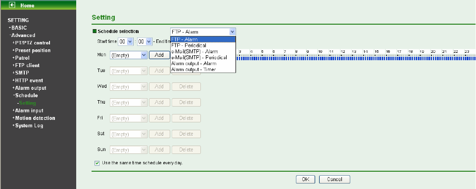
8.8 Schedule
When you click Schedule on the setting-advanced menu, the Setting menu appears. This is the same
menu as the setting menu which is displayed when you click Schedule to set Effective period and
Schedule in FTP client setting menu, and E-Mail (SMTP) setting menu.
Example: When setting e-Mail (SMTP) (the alarm sending) in the Schedule setting menu.
¾ Schedule Selection: Select the list box to specify the schedule you want to set.
z FTP - Alarm
z FTP - Periodical
z e-Mail (SMTP) - Alarm
z e-Mail (SMTP) - Periodical
z Alarm output - Alarm
z Alarm output - Timer
¾ Mon (Monday) to Sun (Sunday): The time period on the right of the checked day is the effective
period of the schedule.
¾ Start time, End time: Specify the Start time and the End time.
71
¾ Use the same time schedule every day: When this is checked, the Start time and End time set to
Mon (Monday) are applied to all days. In this case, the Start time and End time of the other days
than Mon (Monday) cannot be input.
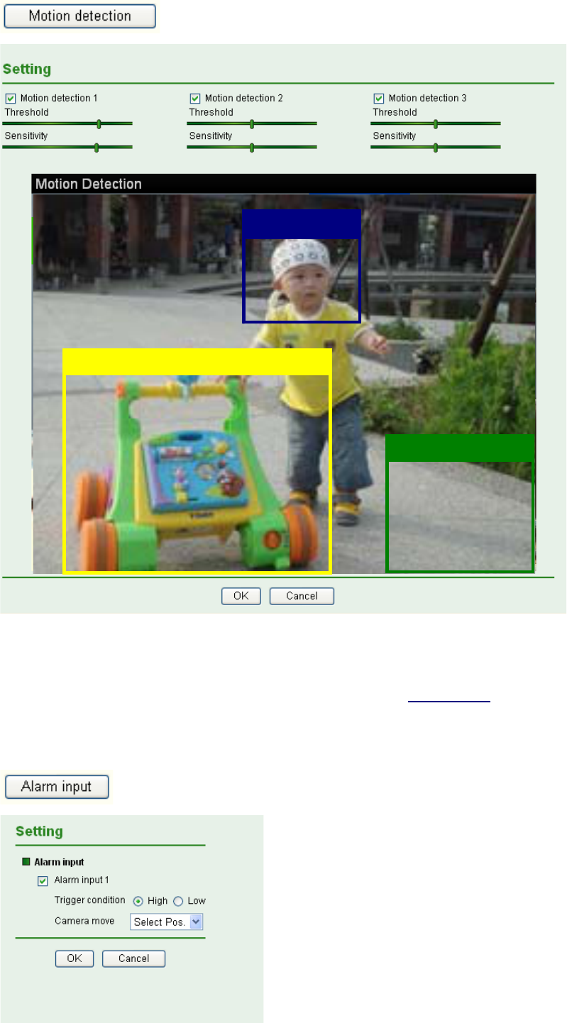
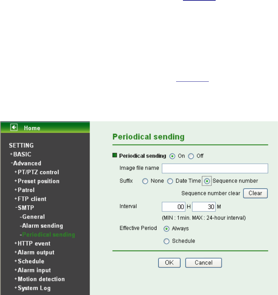
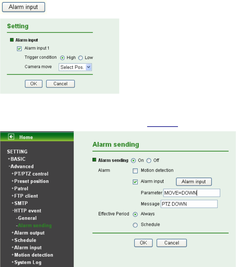
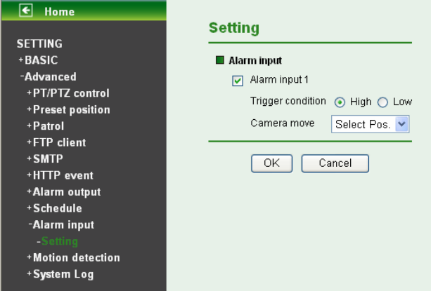
8.9 Alarm Input
When you click Alarm Input on the setting-advanced menu, the Setting menu appears. You can set in
this menu to control the external alarm input of I / O port on the rear of the device linked to FTP, SMTP,
and HTTP sending function.
¾ Alarm input 1: Click it on for using external sensor which is connected to Alarm input1 of the
camera I/O port.
z Trigger condition: Select High signal output and Low signal output as your alarm.
z Camera move: Pull down the window to select the camera preset position. When external
alarm input happens, the camera will automatically move to that position.
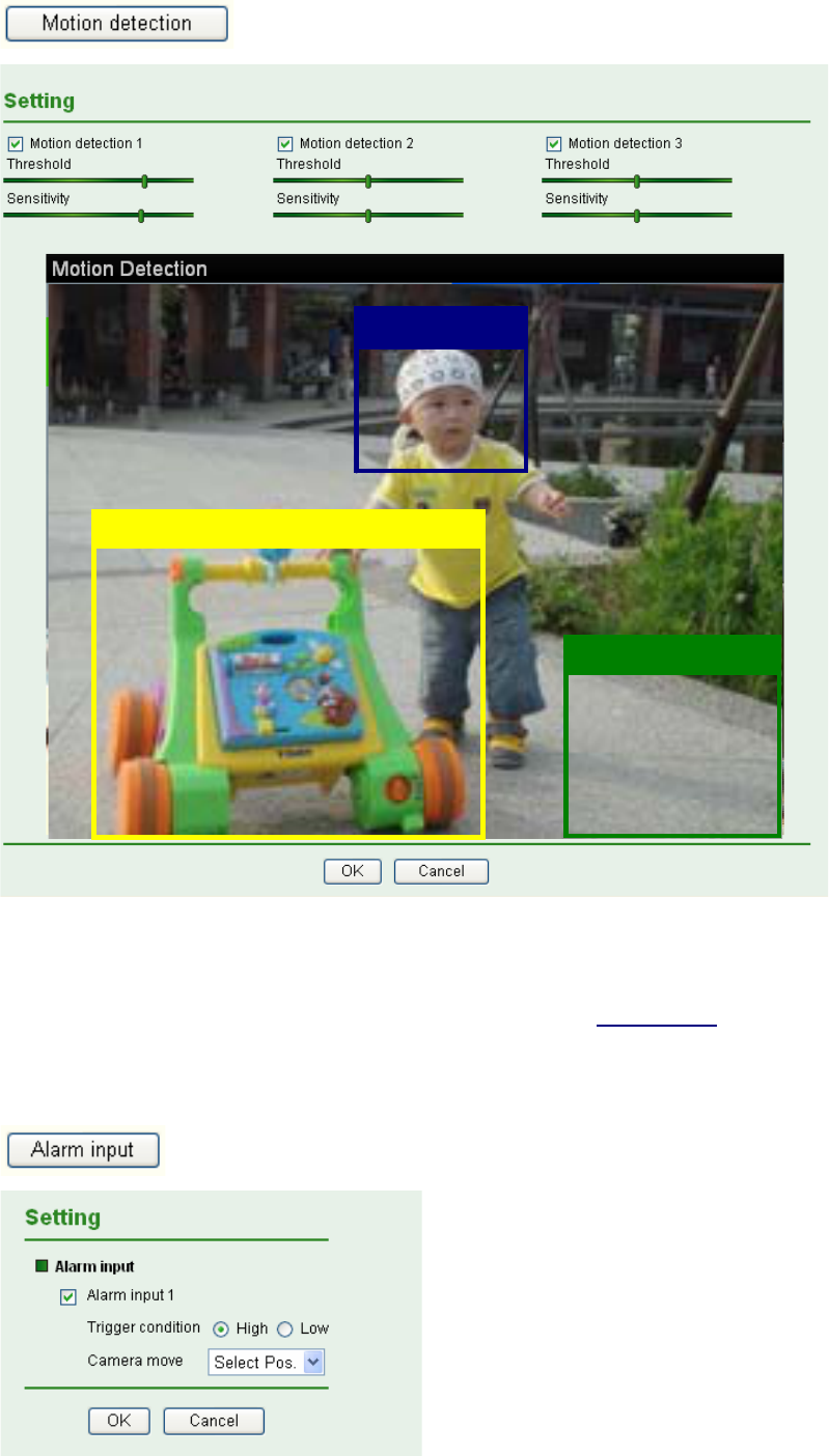
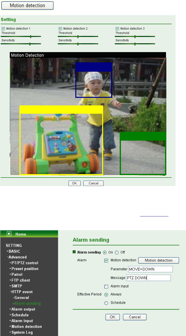
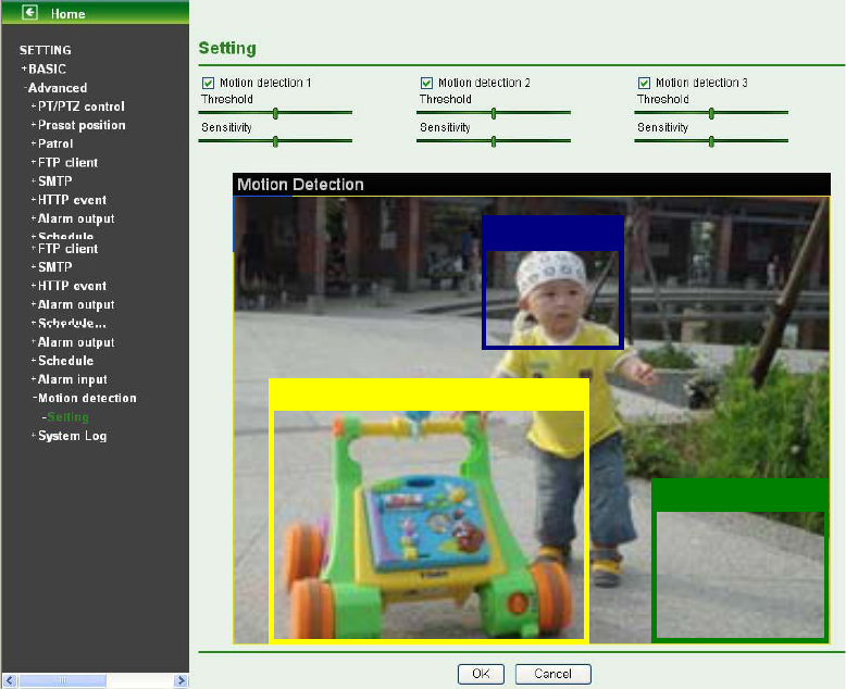
8.10 Motion Detection
There are three Motion Detection functions as sensors to set for different detecting zones. Each one has
Threshold and Sensitivity inputs which you can adjust to specific zone sequentially. Motion Detection
function can support to FTP, SMTP and Alarm output for capturing and sending images or starting alarm
output.
72
¾ Motion Detection 1: Click it on for using Motion Detection 1 function as a sensor. You can adjust
and move the detecting zone by using mouse.
¾ Motion Detection 2: Click it on for using Motion Detection 2 function as a sensor. You can adjust
and move the detecting zone by using mouse.
¾ Motion Detection 3: Click it on for using Motion Detection 3 function as a sensor. You can adjust
and move the detecting zone by using mouse.
z Threshold: It means the extent which the alarm will be triggered. If the tool bar is closer to the
left hand, the threshold is lower; vice versa.
z Sensitivity: It means that how often the sensor will scan the image different. If the tool bar is
closer to the left hand, the sensitivity is lower; vice versa. The higher sensitivity it is and the
more frequently it scans.
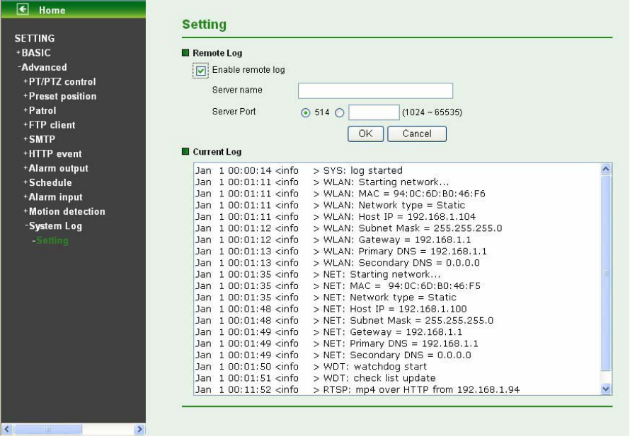
8.11 System Log
The System Log function allows users to review any changes and events happened. The system starts
logging automatically after started.
73
¾ Enable remote log: Enables user to send the log data to a specified log server.

74
Appendix
A. FRAME-RATE AND BITRATE TABLE
Help to set IP Camera with your network environment to access Internet.
Base on your network UPLOAD environment to choose the suitable Image-Quality setting. For example,
if the network environment is ADSL 256Kb/s (upload)/2Mb/s (download), the most fluent Image-Quality
needs to set up under 256 Kb situation.
A.1. MPEG4 @ 30fps / Kbps
Quality 640*480 320*240 160*120
Excellent 1000 300 90
Detailed 400 150 50
Good 300 100 30
Standard 250 70 25
Medium 250 55 20
A.2. MPEG4 / Kbps, fps
Image-Size Bitrate Setting
Frame-Rate
Setting Current Bitrate Current
Frame-Rate
640*480 2048 30 1800 26
640*480 2048 15 2200 16
640*480 1536 30 1500 30
640*480 1536 15 1700 16
640*480 1024 30 1000 30
640*480 1024 15 1000 16
640*480 512 30 500 30
640*480 512 15 600 16
320*240 1536 30 1500 30
320*240 1536 15 1600 16
320*240 1024 30 1000 30
320*240 1024 15 1000 16
320*240 512 30 550 30

75
320*240 512 15 600 16
160*120 1024 30 950 30
160*120 1024 15 750 16
160*120 512 30 500 30
160*120 512 15 50 16
160*120 128 30 130 30
160*120 128 15 140 16
A.3. MJPEG @ 15fps / Kbps
Quality 640*480 320*240 160*120
Excellent 4000 1500 600
Detailed 2400 900 400
Good 1600 650 300
Standard 1300 500 240
Medium 900 350 170
A.4. MJPEG / Kbps, fps
Image-Size Quality Setting
Frame-Rate
Setting Current Bitrate Current
Frame-Rate
640*480 Excellent 15 4000 13
640*480 Excellent 5 1600 5
640*480 Good 15 1600 13
640*480 Good 5 650 5
640*480 Medium 15 900 14
640*480 Medium 5 360 5
320*240 Excellent 15 1500 13
320*240 Excellent 5 550 5
320*240 Good 15 650 13
320*240 Good 5 260 5

76
320*240 Medium 15 350 13
160*120 Medium 5 130 5
160*120 Excellent 15 600 13
160*120 Excellent 5 230 5
160*120 Good 15 300 13
160*120 Good 5 115 5
160*120 Medium 15 170 13
160*120 Medium 5 65 5
B. STORAGE REQUIREMENT TABLE
Help to set Recording Storage System. Please refer to the following table to find out the capability for
recording into your hard disk.
B.1. MPEG4 Storage Requirement GB / channel / day @ 30fps
Quality 640*480 320*240 160*120
Excellent 10.5 3.2 0.9
Detailed 4.2 1.6 0.5
Good 3.2 1.1 0.3
Standard 2.6 0.7 0.3
Medium 2.6 0.6 0.2
B.2. MPEG4 Storage Requirement GB / channel / day @ 15fps
Quality 640*480 320*240 160*120
Excellent 5.3 1.6 0.4
Detailed 2.1 0.8 0.3
Good 1.6 0.6 0.2
Standard 1.3 0.4 0.1
Medium 1.3 0.3 0.1
B.3. MPEG4 Storage Requirement GB / channel / day
Image-Size Bitrate Setting Frame-Rate Setting Current Bitrate

77
640*480 2048 30 23.0
640*480 2048 15 22.2
640*480 1536 30 18.5
640*480 1536 15 17.9
640*480 1024 30 10.5
640*480 1024 15 10.5
640*480 512 30 5.3
640*480 512 15 6.3
320*240 1536 30 15.8
320*240 1536 15 16.9
320*240 1024 30 10.5
320*240 1024 15 10.5
320*240 512 30 5.8
320*240 512 15 6.3
160*120 1024 30 10.0
160*120 1024 15 7.9
160*120 512 30 5.3
160*120 512 15 0.5
160*120 128 30 1.4
160*120 128 15 1.5
B.4. MJPEG Storage Requirement GB / channel / day @ 15fps
Quality 640*480 320*240 160*120
Excellent 42.2 15.8 6.3
Detailed 25.3 9.5 4.2
Good 16.9 6.9 3.2
Standard 13.7 5.3 2.5
Medium 9.5 3.7 1.8

78
B.5. MJPEG Storage Requirement GB / channel / day
Image-Size Quality Setting Frame-Rate Setting Current Bitrate
640*480 Excellent 15 42.2
640*480 Excellent 5 16.9
640*480 Good 15 16.9
640*480 Good 5 6.9
640*480 Medium 15 9.5
640*480 Medium 5 3.8
320*240 Excellent 15 15.8
320*240 Excellent 5 5.8
320*240 Good 15 6.9
320*240 Good 5 2.7
320*240 Medium 15 3.7
160*120 Medium 5 1.4
160*120 Excellent 15 6.3
160*120 Excellent 5 2.4
160*120 Good 15 3.2
160*120 Good 5 1.2
160*120 Medium 15 1.8
160*120 Medium 5 0.7

79
C. TESTING SYSTEM SPECIFICATION
Software: MainConsole Version 2.6.4 Professional
CPU: AMD Athlon 64*2 @3600+MHz
Memory: 2048 MB (2 x 1024 DDR2-SDRAM )
Ethernet: VIA Rhine II Fast Ethernet Adapter
Hard Disk: ST3250620A (250 GB)
Graphic card: ATI Technologies Inc EAX1600 Series
Operating System: Windows XP Professional SP2 x64
D. PERFORMANCE OF 16 CHANNEL IP CAMERA
Results from Test with a Resolution of 704×480 CCD IPCamera
704x480 Quality Frame Rate CPU Load Bandwidth
16 IP camera Excellent 30 95% 15~20 Mbps
Results from Test with a Resolution of 640×480 CMOS IPCamera
640x480 Quality Frame Rate CPU Load Bandwidth
16 IP camera Excellent 30 95% 10~15 Mbps

80
Europe – EU Declaration of Conformity
This device complies with the essential requirements of the R&TTE Directive 1999/5/EC. The following
test methods have been applied in order to prove presumption of conformity with the essential
requirements of the R&TTE Directive 1999/5/EC:
Clause Description
EN 60950-1: 2001 Safety of Information Technology Equipment
EN 50392: 2004 Generic standard to demonstrate the compliance of electronic and
electrical apparatus with the basic restrictions related to human
exposure to electromagnetic fields (0 Hz - 300 GHz)
EN 300 328 V1.6.1
(2004-11)
Electromagnetic compatibility and Radio spectrum Matters (ERM);
Wideband transmission systems; Data transmission equipment
operating in the 2,4 GHz ISM band and using wide band modulation
techniques; Harmonized EN covering essential requirements under
article 3.2 of the R&TTE Directive
EN 301 489-17 V1.2.1
(2002-08) and EN 301
489-1 V1.5.1 (2004-11)
Electromagnetic compatibility and Radio spectrum Matters (ERM);
ElectroMagnetic Compatibility (EMC) standard for radio equipment
and services; Part 17: Specific conditions for 2,4 GHz wideband
transmission systems and 5 GHz high performance RLAN
equipment
This device is a 2.4 GHz wideband transmission system (transceiver), intended for use in all EU member
states and EFTA countries, except in France and Italy where restrictive use applies.
In Italy the end-user should apply for a license at the national spectrum authorities in order to obtain
authorization to use the device for setting up outdoor radio links and/or for supplying public access to
telecommunications and/or network services.
This device may not be used for setting up outdoor radio links in France and in some areas the RF
output power may be limited to 10 mW EIRP in the frequency range of 2454 – 2483.5 MHz. For detailed
information the end-user should contact the national spectrum authority in France.

81
Federal Communication Commission Interference Statement
This equipment has been tested and found to comply with the limits for a Class B digital device, pursuant
to Part 15 of the FCC Rules. These limits are designed to provide reasonable protection against
harmful interference in a residential installation. This equipment generates, uses and can radiate radio
frequency energy and, if not installed and used in accordance with the instructions, may cause harmful
interference to radio communications. However, there is no guarantee that interference will not occur in
a particular installation. If this equipment does cause harmful interference to radio or television
reception, which can be determined by turning the equipment off and on, the user is encouraged to try to
correct the interference by one of the following measures:
x Reorient or relocate the receiving antenna.
x Increase the separation between the equipment and receiver.
x Connect the equipment into an outlet on a circuit different from that to which the receiver is
connected.
x Consult the dealer or an experienced radio/TV technician for help.
This device complies with Part 15 of the FCC Rules. Operation is subject to the following two conditions:
(1) This device may not cause harmful interference, and
(2) this device must accept any interference received, including interference that may cause
undesired operation.
FCC Caution:
Any changes or modifications not expressly approved by the party responsible for compliance could void
the user's authority to operate this equipment.
IEEE 802.11b or 802.11g operation of this product in the U.S.A. is firmware-limited to channels 1 through
11.
IMPORTANT NOTE:
FCC Radiation Exposure Statement:
This equipment complies with FCC radiation exposure limits set forth for an uncontrolled environment.
This equipment should be installed and operated with minimum distance 20cm between the radiator &
your body.
This transmitter must not be co-located or operating in conjunction with any other antenna or transmitter.