TP Link Technologies WA7110ND 2.4GHz 150Mbps High Power Wireless Access Point User Manual TL WA7110ND Part2
TP-Link Technologies Co., Ltd. 2.4GHz 150Mbps High Power Wireless Access Point TL WA7110ND Part2
Contents
- 1. TL-WA7110ND_User Manual-Part1
- 2. TL-WA7110ND_User Manual-Part2
- 3. TL-WA7110ND_User Manual-Part3
TL-WA7110ND_User Manual-Part2
TL-WA7110ND 150Mbps High Power Wireless Access Point User Guide
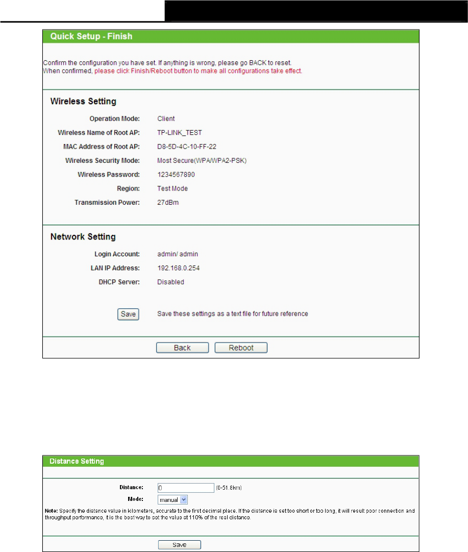
Note:
Figure 3-40 Finish page
If the wireless connection is poor after basic configuration of operation mode,
please select Wireless >Distance Setting, and set the outdoor distance value at 110% of the
real distance as shown in Figure 3-41. It will help you stabilize outdoor links.
Figure 3-41 Distance Setting
38
TL-WA7110ND 150Mbps High Power Wireless Access Point User Guide
Chapter 4. AP & Multi-SSID & Repeater (Range Extender)
& Bridge with AP & Client Operation Mode
This Chapter describes how to configure some advanced settings for your Access Point through
the web-based management page in standard AP operation mode including AP,
Multi-SSID, Repeater (Range Extender), Bridge with AP and Client mode. In the following
explanations, we will take the device in Access Point operation mode for example.
4.1 Login
After your successful login, you can configure and manage the Access Point. There
are eight main menus on the left of the Web-based management page. Submenus will be
available after you click one of the main menus. The eight main menus are: Status,Quick
Setup,Operation Mode,WPS,Network,Wireless,DHCP and System Tools. On
the right of the Web-based management page, there are the detailed explanations
and instructions for the corresponding page. To apply any settings you have altered on the
page, please click Save.
The detailed explanations for each Web page key’s function are listed below.
4.2 Status
Selecting Status will enable you to view the AP’s current status and configuration, all of which is
read-only.
Figure 4-1 Status
39
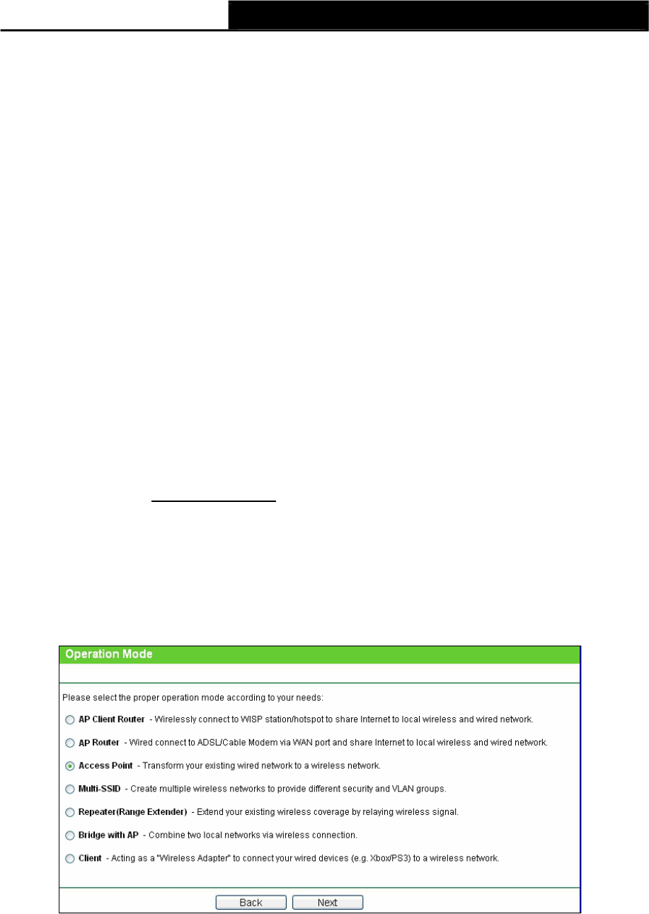
1. Wired
TL-WA7110ND 150Mbps High Power Wireless Access Point User Guide
This field displays the current settings or information for the LAN, including the MAC address,IP
address and Subnet Mask.
2. Wireless
This field displays basic information or status for wireless function, including Operation Mode,
Name (SSID),Channel,Mode,Channel Width and MAC address.
3. WAN
These parameters apply to the WAN port of the router, including MAC address,IP
address,Subnet Mask,Default Gateway and DNS server. If PPPoE is chosen as the WAN
connection type, the Disconnect button will be shown here while you are accessing the
Internet. You can also cut the connection by clicking the button. If you have not connected to the
Internet, just click Connect to establish the connection.
4. Traffic Statistics
This field displays the router's traffic statistics.
5. System Up Time
The total up time of the router since it was powered on or reset.
4.3 Quick Setup
Please refer to Section 3.2: "Quick Setup".
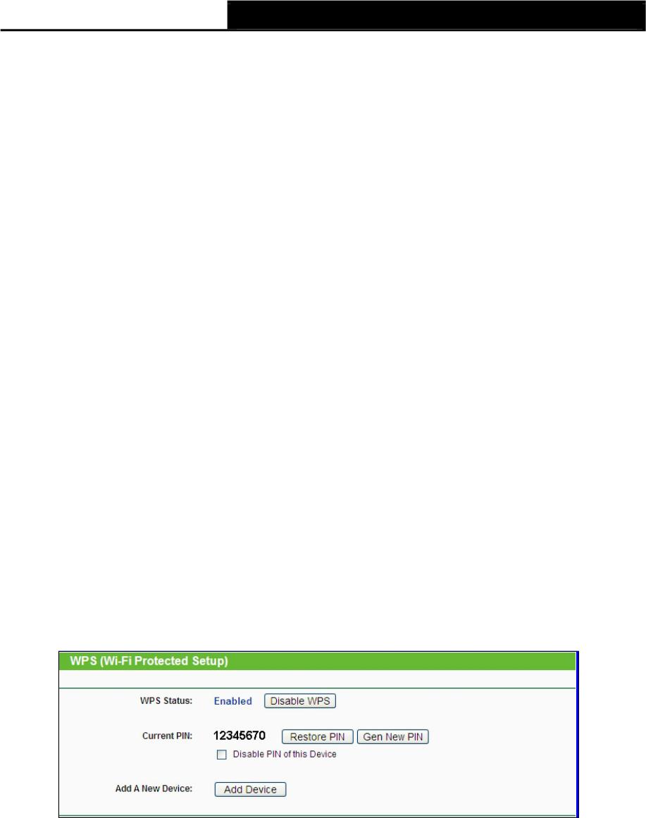
4.4 Operation Mode
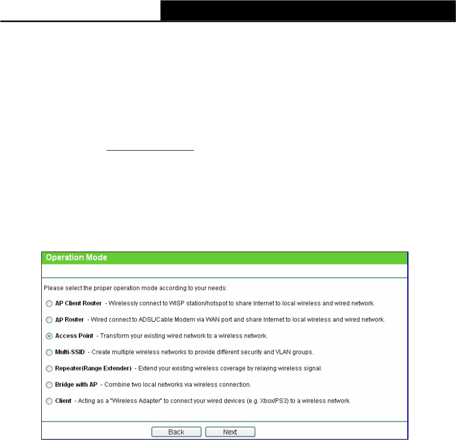
Selecting Operation Mode will allow you to choose the operation mode for the
AP. The AP supports seven operation mode types, AP Client Router,AP Router,Access
Point,Multi-SSID,Repeater (Range Extender),Bridge with AP and Client. Please select
the one your want as shown in Figure 4-2. Click Save to save your choice.
Figure 4-2 Operation Mode
AP Client Router - In this mode, the device enables multi-users to share Internet from WISP.
The LAN port devices share the same IP from WISP through Wireless port. While connecting
to WISP, the Wireless port works as a WAN port at AP Client Router mode. The Ethernet
port acts as a LAN port.
40
TL-WA7110ND 150Mbps High Power Wireless Access Point User Guide
AP Router - In this mode, the device enables multi-users to share Internet via ADSL/Cable
Modem. The wireless port share the same IP to ISP through Ethernet
WAN port. The Wireless port acts the same as a LAN port while at AP Router mode.
Access Point - In this mode, the device can be connected to a wired network and transform
the wired access into wireless that multiple devices can share together,
especially for a home, office or hotel where only wired network is available.
Multi-SSID - In this mode, the device can create up to 4 wireless networks
labeled with different SSIDs and assign each SSID with different security or
VLAN, especially for the situation when the various access policies and functions are
required.
Repeater(Range Extender) - In this mode, the device can copy and reinforce the existing
wireless signal to extend the coverage of the signal, especially for a large space to eliminate
signal-blind corners.
Bridge with AP - In this mode, the device can be used to combine multiple local networks
together to the same one via wireless connections, especially for a home or office where
separated networks can't be connected easily together with a cable.
Client - In this mode, the device can be connected to another device via Ethernet port and
act as an adaptor to grant your wired devices access to a wireless network, especially for a
Smart TV, Media Player, or game console only with an Ethernet port.
Note:
When you change the operation mode to Client/Repeater, WPS function will stay disabled. Please
manually enable this function if needed when you switch back to Access Point/Multi-SSID/Bridge
mode.
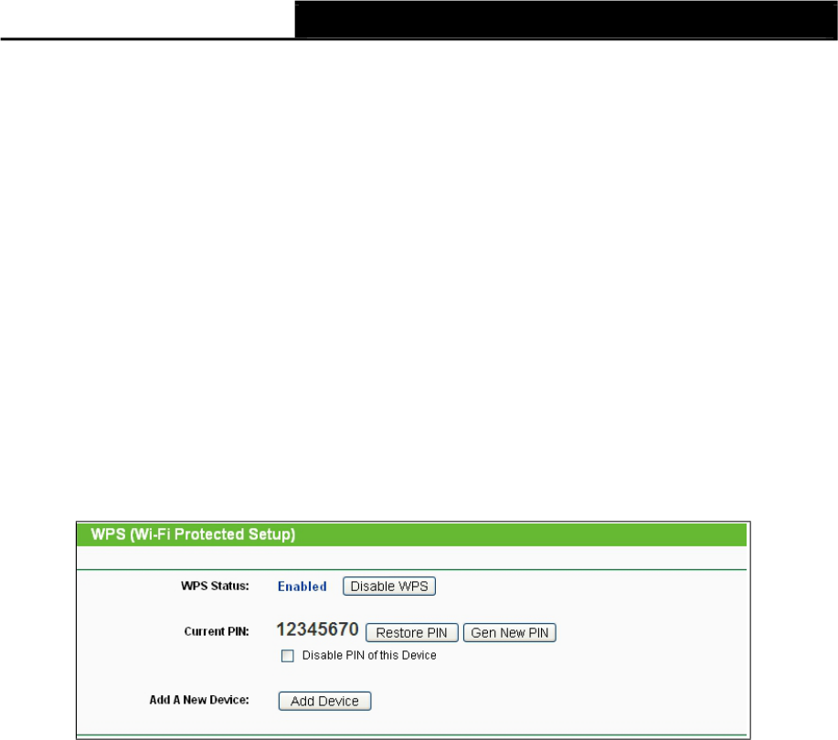
4.5 WPS
Choose WPS in the main menu, you will see the page as shown in Figure 4-3. The WPS function
is disabled and cannot be configured in the standard AP mode.
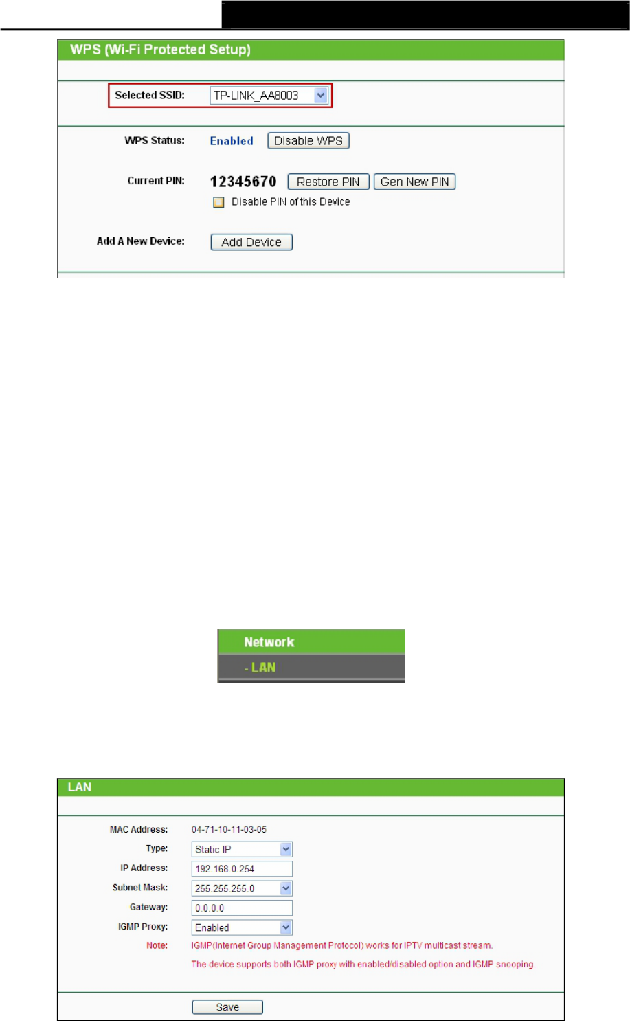
Figure 4-3 WPS
Selected SSID - If Multi-SSID is enabled, you can choose one of the SSIDs
from the pull-down list.
41
TL-WA7110ND 150Mbps High Power Wireless Access Point User Guide
WPS Status - Enable or disable the WPS function here.
Current PIN - The current value of the device's PIN displayed here. The default PIN of the
device can be found in the label or User Guide.
Restore PIN - Restore the PIN of the device to its default.
Gen New PIN - Click this button, and then you can get a new random value for the device's
PIN. You can ensure the network security by generating a new PIN.
Disable PIN of this Device - WPS external registrar of entering the device's PIN can be
disabled or enabled manually. If the device receives multiple failed attempts to authenticate
an external Registrar, this function will be disabled automatically.
Add Device - You can add the new device to the existing network manually by clicking this
button.
4.6 Network
The Network option allows you to customize your local network manually by changing the default
settings of the AP.
4.6.1
LAN
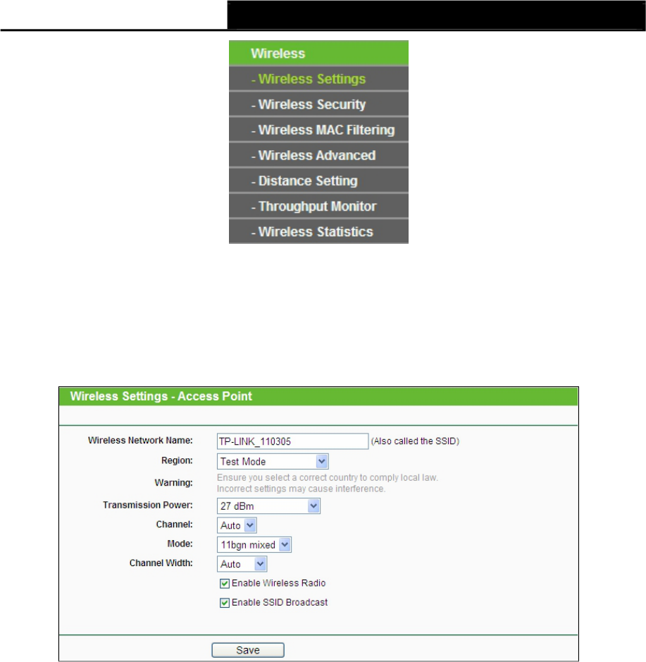
Figure 4-4 the Network menu
Selecting Network > LAN will enable you to configure the IP parameters of LAN port on this page.
Figure 4-5 LAN
42

TL-WA7110ND 150Mbps High Power Wireless Access Point User Guide
MAC Address - The physical address of the router, as seen from the LAN. The value can't
be changed.
Type - Choosing dynamic IP to get IP address from DHCP server, or choosing static IP to
configure IP address manually.
IP Address - Enter the IP address of your router in dotted-decimal notation (factory default:
192.168.0.254).
Subnet Mask - An address code that determines the size of the network.
Normally use
255.255.255.0 as the subnet mask.
Gateway - The gateway should be in the same subnet as your IP address.
IGMP Proxy – IGMP (Internet Group Management Protocol) works for IPTV multicast stream.
The device supports both IGMP proxy with enabled/disabled option and IGMP snooping.
Note:
1) If you change the IP Address of LAN, you must use the new IP Address to login the Router.
2) If the new LAN IP Address you set is not in the same subnet, the IP Address pool of the DHCP
server will not take effect until they are re-configured.
3) If the new LAN IP Address you set is not in the same subnet, the Virtual Server and DMZ Host
will change accordingly at the same time.
4) The device will reboot automatically after you click the Save button.
4.7 Wireless
The Wireless option, improving functionality and performance for wireless network, can help you
to make the AP an ideal solution for your wireless network.
Here you can create a wireless local area network just through a few settings. Basic Settings is
used for the configuration of some basic parameters of the AP. Wireless Mode
allows you to select the mode that AP works on. Security Settings provides three
different security types to secure your data and thus provide greater security for your wireless
network. MAC filtering allows you to control the access of wireless stations to the
AP. Wireless Statistics shows you the statistics of current connected Wireless stations.
Distance Setting is used to adjust the wireless range in outdoor conditions. Throughput Monitor
helps to watch wireless throughput information Wireless statistics enables you to get detailed
information about the current connected wireless stations.
There are eight submenus under the Wireless menu (shown in Figure 4-6): Wireless Settings,
Wireless Security,Wireless MAC Filtering,Wireless Advanced,
Distance Setting,Throughput Monitor and Wireless Statistics. Click any of
them, and you will be able to configure the corresponding function. The detailed
explanations for each submenu are provided below.
43
TL-WA7110ND 150Mbps High Power Wireless Access Point User Guide
4.7.1 Wireless
Settings
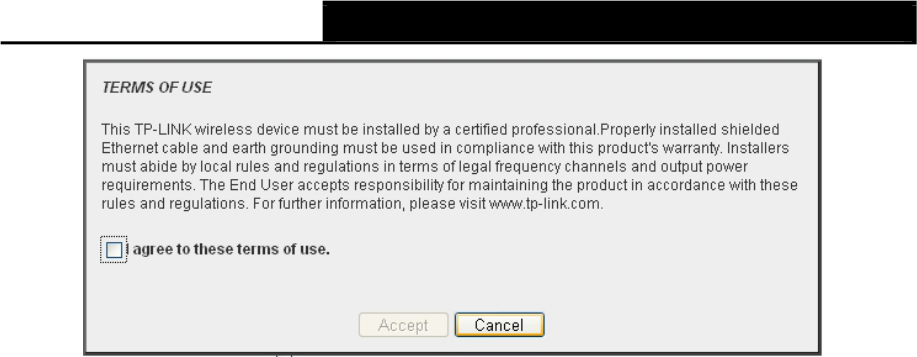
Figure 4-6 Wireless menu
Selecting Wireless >Wireless Settings will enable you to configure the basic settings for your
wireless network on the screen below (Figure 4-7).
Figure 4-7 Wireless Settings in AP Client Router mode
Wireless Network Name - Enter a string of up to 32 characters. The same Name (SSID)
must be assigned to all wireless devices in your network. The default SSID is
set to be
(XXXXXX indicates the last unique six characters of each device's MAC address), which can
ensure your wireless network security. But it is strongly recommended that you change your
networks name (SSID) to a different value. This value is case-sensitive. For example, TEST
is NOT the same as test.
Region - Select your region from the pull-down list. This field specifies the region where the
wireless function of the device can be used. It may be illegal to use the wireless function of
the device in a region other than one of those specified in this field. If your country or region is
not listed, please contact your local government agency for assistance.
When you select your local region from the pull-down list, the Note Dialog of TERMS OF USE
will pop up. Select I agree to these terms of use, and click Accept to continue.
44
TL-WA7110ND 150Mbps High Power Wireless Access Point User Guide
Note:
Note Dialog
Ensure you select a correct country to comply with local laws. Incorrect settings may cause
interference. Limited to local law of the United States, selecting country code and channel
function was disabled.
Transmission Power - The available options of transmission power are determined by the
region selected.
Channel - This field determines which operating frequency will be used. It is not necessary to
change the wireless channel unless you notice interference problems with another nearby
access point.
Mode - This field determines the wireless mode which the AP works on. The options includes:
11b only, 11g only, 11n only, 11bg mixed, 11bgn mixed.
Channel Width - The bandwidth of the wireless channel.
Enable Wireless Radio - The wireless radio of the AP can be enabled or disabled to allow or
deny wireless stations to access. If enabled, the wireless stations will be able to access the
AP, otherwise, wireless stations will not be able to access the AP.
Enable SSID Broadcast - If you select the Enable SSID Broadcast checkbox, the AP will
broadcast its name (SSID) on the air.
Be sure to click the Save button to save your settings on this page.
Note:
The device will reboot automatically after you click the Save button.
4.7.2 Wireless Security
Selecting Wireless >Wireless Security will enable you to configure the security of the wireless
network for your device on the page as shown in Figure 4-8.
45
TL-WA7110ND 150Mbps High Power Wireless Access Point User Guide
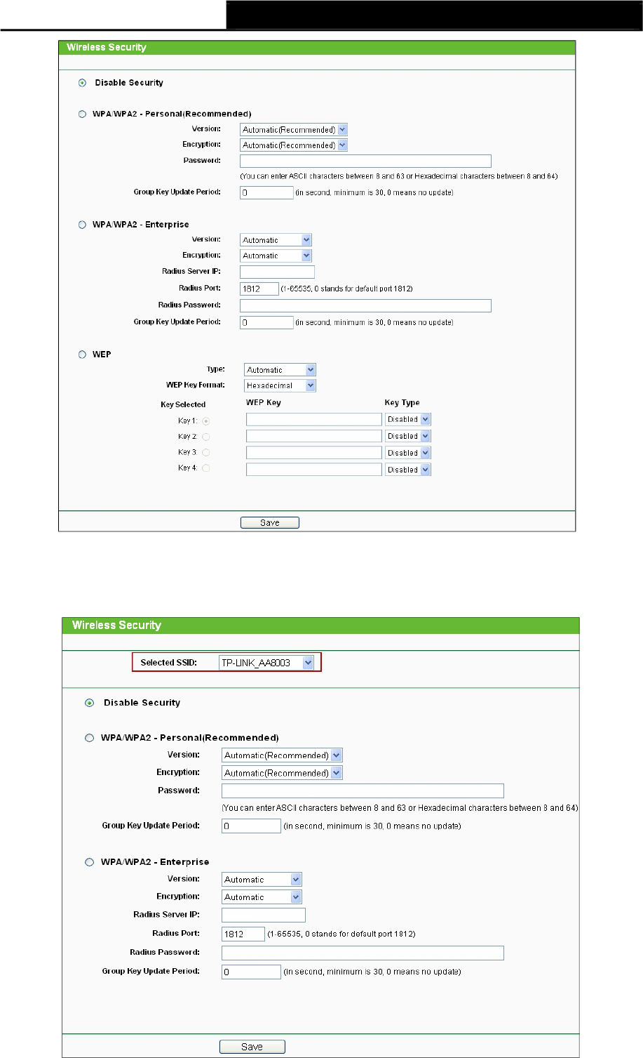
Figure 4-8 Wireless Security
Selected SSID: If Multi-SSID is enabled, you can choose one of the SSIDs
from the pull-down list.
46

TL-WA7110ND 150Mbps High Power Wireless Access Point User Guide
Disable Security - The wireless security function can be enabled or disabled. If disabled, the
wireless stations will be able to connect the device without encryption. It is recommended
strongly that you choose one of following options to enable security.
WPA/WPA2-Personal - Select WPA based on Radius Server.
WPA/WPA2-Enterprise - Select WPA based on pre-shared passphrase.
WEP - Select 802.11 WEP security.
Each security option has its own settings as described below:
WPA/WPA2 – Personal (Recommended)
WEP - Select 802.11 WEP security.
Version - You can select one of following versions:
Automatic - Select WPA-Personal or WPA2-Personal automatically based
on the wireless station's capability and request.
WPA-Personal - Pre-shared key of WPA.
WPA2-Personal - Pre-shared key of WPA2.
Encryption - You can select either Automatic, or TKIP or AES.
Password - You can enter ASCII or Hexadecimal characters. For Hexadecimal, the length
should be between 8 and 64 characters; for ASCII, the length should be between 8 and 63
characters.
Group Key Update Period - Specify the group key update interval in seconds. The value
can be either 0 or at least 30. Enter 0 to disable the update.
WPA/WPA2 - Enterprise
WEP - Select 802.11 WEP security.
Version - You can select one of following versions:
Automatic - Select WPA or WPA2 automatically based on the wireless
station's capability and request.
WPA - Wi-Fi Protected Access.
WPA2 - WPA version 2.
Encryption - You can select either Automatic, or TKIP or AES.
Radius Server IP - Enter the IP address of the Radius Server.
Radius Port - Enter the port that radius service uses.
Radius Password - Enter the password for the Radius Server.
Group Key Update Period - Specify the group key update interval in seconds. The value
can be either 0 or at least 30. Enter 0 to disable the update.
WEP
Type - You can select one of following types:
Automatic - Select Shared Key or Open System authentication type
automatically based on the wireless station's capability and request.
Open System - Select 802.11 Open System authentication.
Shared Key - Select 802.11 Shared Key authentication.
WEP Key Format - You can select ASCII or Hexadecimal format. ASCII Format stands for
any combination of keyboard characters in the specified length. Hexadecimal format stands
for any combination of hexadecimal digits (0-9, a-f, A-F) in the specified length.
47
TL-WA7110ND 150Mbps High Power Wireless Access Point User Guide
WEP Key settings - Select which of the four keys will be used and enter the matching WEP
key information for your network in the selected key radio button. These values
must be identical on all wireless stations in your network.
Key Type - You can select the WEP key length (64-bit, or 128-bit, or 152-bit.) for encryption.
"Disabled" means this WEP key entry is invalid.
For 64-bit encryption - You can enter 10 hexadecimal digits (any combination of 0-9, a-f,
A-F, and null key is not permitted) or 5 ASCII characters.
For 128-bit encryption - You can enter 26 hexadecimal digits (any combination of 0-9, a-f,
A-F, and null key is not permitted) or 13 ASCII characters.
For 152-bit encryption - You can enter 32 hexadecimal digits (any combination of 0-9, a-f,
A-F, and null key is not permitted) or 16 ASCII characters.
Note:
If you do not set the key, the wireless security function is still disabled even if you have selected
Shared Key as Authentication Type.
Be sure to click the Save button to save your settings on this page.
4.7.3 Wireless MAC Filtering
Selecting Wireless >Wireless MAC Filtering will allow you to set up some
filtering rules to control wireless stations accessing the device, which depend on the station’s
MAC address on the following screen as shown Figure 4-9.
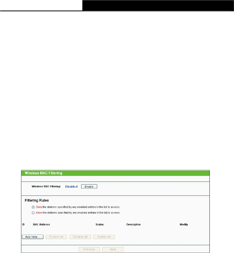
Figure 4-9 Wireless MAC address Filtering
The Wireless MAC Address Filtering feature allows you to control wireless stations accessing the
AP, which depend on the station's MAC addresses.
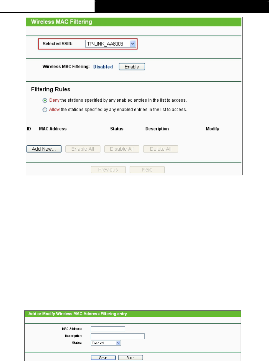
Selected SSID - If Multi-SSID is enabled, you can choose one of the SSIDs
from the pull-down list.
48
TL-WA7110ND 150Mbps High Power Wireless Access Point User Guide
MAC Address - The wireless station's MAC address that you want to access.
Status - The status of this entry either Enabled or Disabled.
Description - A simple description of the wireless station.
Modify - Here you can modify or delete an existing rule.
To disable the Wireless MAC Address Filters feature, keep the default setting, Disable.
To set up an entry, click Enable, and follow these instructions:
First, you must decide whether the specified wireless stations can or cannot access the AP. If you
desire that the specified wireless stations can access the AP, please select the radio button Allow
the stations specified by any enabled entries in the list to access, otherwise, select the radio
button Deny the stations specified by any enabled entries in the list to access.
To Add a Wireless MAC Address filtering entry, clicking the Add New... button, and following
these instructions: The “Add or Modify Wireless MAC Address Filtering entry"
page will appear, shown in Figure 4-10.
Figure 4-10 Add or Modify Wireless MAC Address Filtering entry
1. Enter the appropriate MAC Address into the MAC Address field. The format of the MAC
Address is XX-XX-XX-XX-XX-XX (X is any hexadecimal digit).
For example,
00-0A-EB-B0-00-0B.
2. Enter a simple description of the wireless station in the Description field. For example,
Wireless station A.
3. Status - Select Enabled or Disabled for this entry on the Status pull-down list.
4. Click the Save button to save this entry.
To add another entries, repeat steps 1~4.
49

TL-WA7110ND 150Mbps High Power Wireless Access Point User Guide
To modify or delete an existing entry:
1. Click the Modify or Delete button in the modify column in the MAC Address
Filtering
Table.
2. Enter the value as desired in the Add or Modify Wireless MAC Address Filtering entry
page, and click the Save button.
You can click the Enable All button to make all the Entries enabled, click the Disable All button to
make all the Entries disabled, click the Delete All button to delete all the entries.
Click the Next button to go to the next page and click the Previous button to
return to the previous page.
Note: If you enable the function and select the Allow the stations specified by any enabled
entries in the list to access for Filtering Rules, and there are not any enable entries in the list,
thus, no wireless stations can access the AP.
For example: If you desire that the wireless station A with MAC address 00-0A-EB-00- 07-BE be
able to access the router. The wireless station B with MAC address 00-0A-EB- 00-07-5F not be able
to access the router, while all other wireless stations cannot access the router, you should configure
the Wireless MAC Address Filtering list by following these steps:
1. Click the Enable button to enable this function.
2. Select the radio button: Allow the stations specified by any enabled entries in the list to
access for Filtering Rules.
3. Delete all or disable all entries if there are any entries already.
4. Click the Add New... button and enter the MAC address 00-0A-EB-00-07-BE in
the MAC Address field, enter wireless station A in the Description field and
select Enabled in the Status pull-down list. Click the Save button.
5. Click the Add New... button and enter the MAC address 00-0A-EB-00-07-5F in
the MAC Address field, enter wireless station B in the Description field and select
Disabled in the Status pull-down list. Click the Save button.
The filtering rules that configured should be similar to the following list:
Note:
1) If you select the radio button Deny the stations specified by any enabled entries in the list
to access for Filtering Rules, the wireless station B will still not be able to access the router,
however, other wireless stations that are not in the list will be able to access the router.
2) If you enable the function and select the Allow the stations specified by
any enabled entries in the list to access for Filtering Rules, and there are not any
enable entries in the list, thus, no wireless stations can access the router.
4.7.4 Wireless Advanced
Selecting Wireless > Wireless Advanced will allow you to do some advanced settings for the
device in the following screen as shown in Figure 4-11. As the configuration for each operation
mode is almost the same, we take Access Point mode for example here.
50
TL-WA7110ND 150Mbps High Power Wireless Access Point User Guide
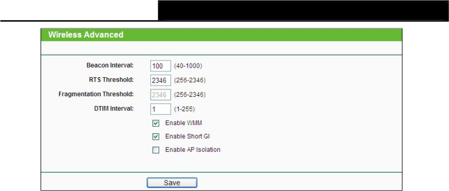
Figure 4-11 Wireless Advanced
Beacon Interval - The beacons are the packets sent by the Device to synchronize a wireless
network. Beacon Interval value determines the time interval of the beacons. You can specify
a value between 40-1000 milliseconds. The default value is 100.
RTS Threshold - Here you can specify the RTS (Request to Send) Threshold. If the packet
is larger than the specified RTS Threshold size, the Device will send RTS
frames to a particular receiving station and negotiate the sending of a data frame. The
default value is
2346.
Fragmentation Threshold - This value is the maximum size determining whether packets
will be fragmented. Setting the Fragmentation Threshold too low may result in poor network
performance since excessive packets. 2346 is the default setting and is recommended.
DTIM Interval - This value determines the interval of the Delivery Traffic Indication Message
(DTIM). You can specify the value between 1-255 Beacon Intervals. The default value is 1,
which indicates the DTIM Interval is the same as Beacon Interval.
Enable WMM - WMM function can guarantee the packets with high-priority messages being
transmitted preferentially. It is strongly recommended enabled.
Enable Short GI - This function is recommended, for it will increase the data capacity by
reducing the guard interval time.
Enable AP Isolation - Isolate all connected wireless stations so that wireless stations cannot
access each other through WLAN. This function will be disabled if WDS/Bridge is enabled.
Note:
If you are not familiar with the setting items in this page, it's strongly recommended to keep the
provided default values; otherwise it may result in lower wireless network performance.
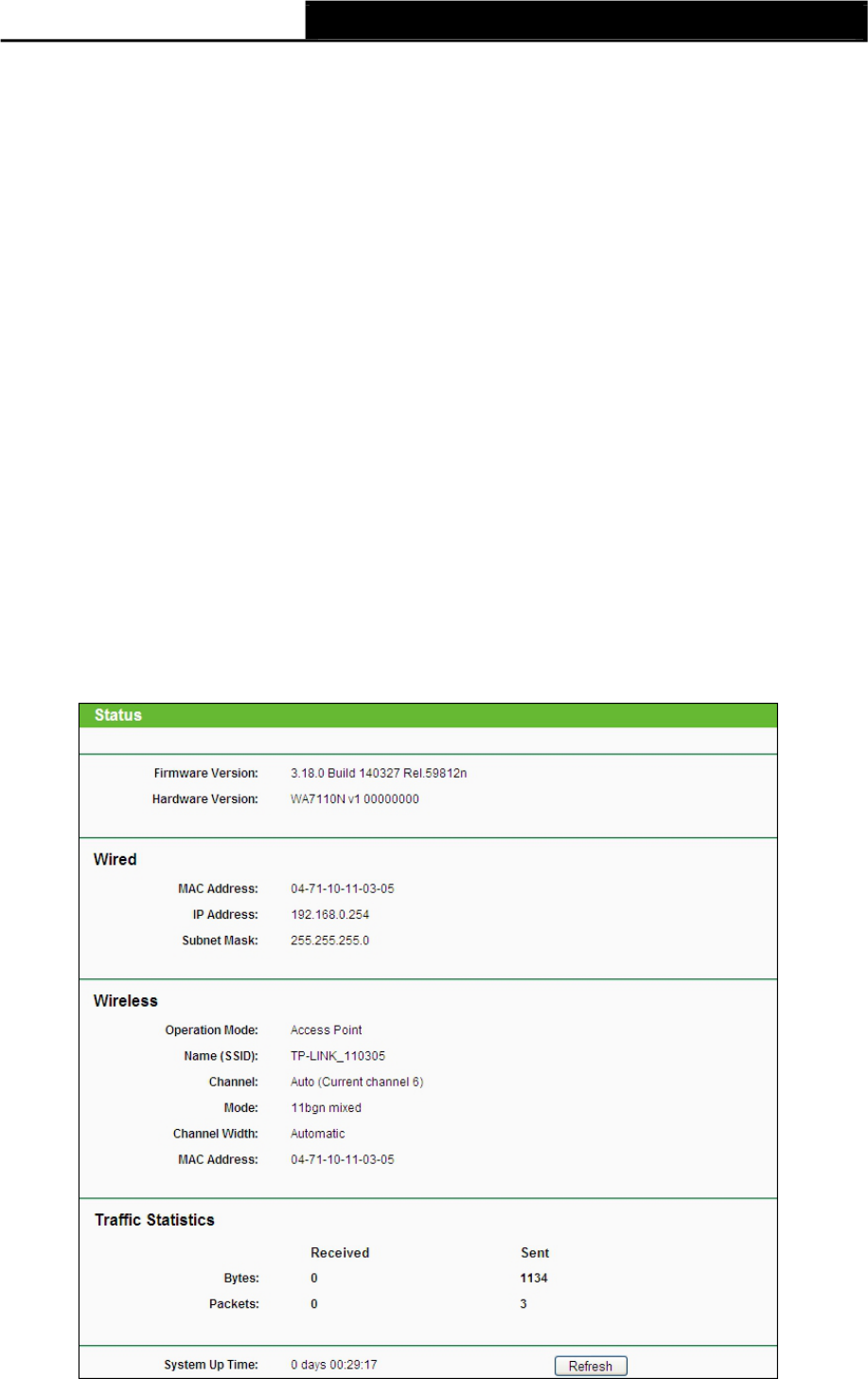
4.7.5 Distance Setting
Selecting Wireless >Distance Setting will allow you to adjust the wireless range
in outdoor conditions as shown in Figure 4-12. This is a critical feature required for stabilizing
outdoor links. Enter the distance of your wireless link and the software will optimize
the frame ACK timeout value automatically.
51
TL-WA7110ND 150Mbps High Power Wireless Access Point User Guide
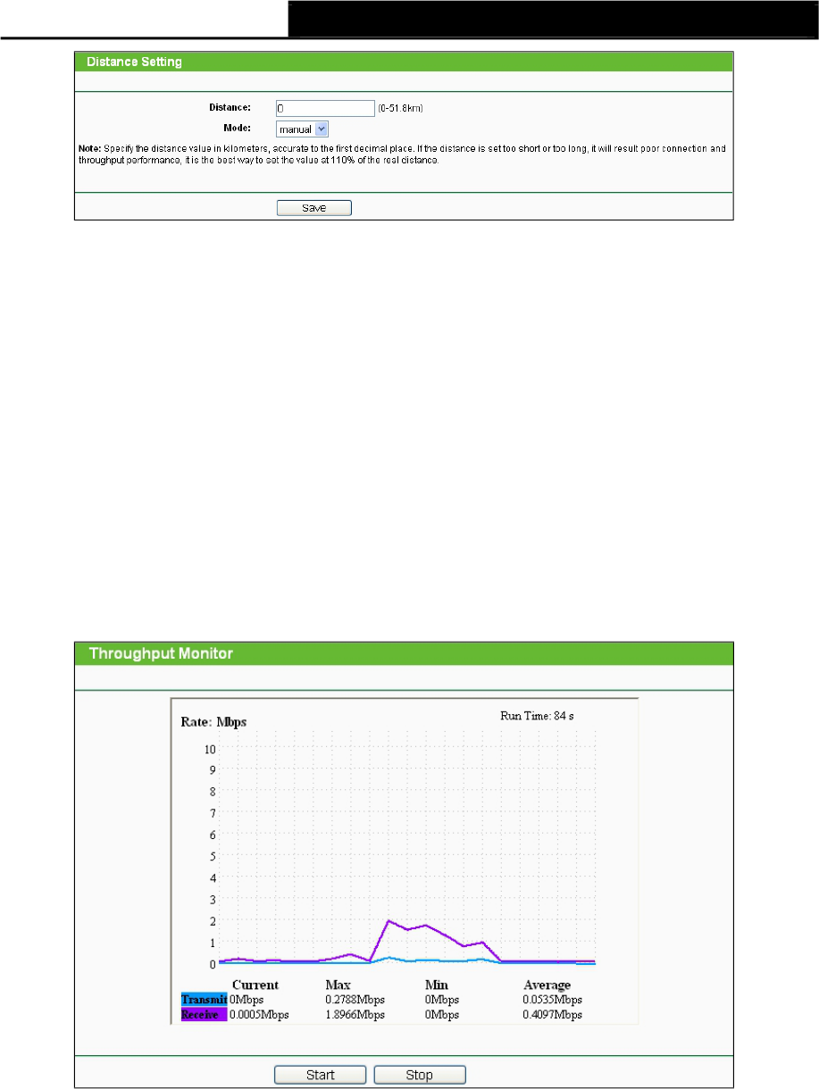
Figure 4-12 Distance Setting
Distance - Specify the distance value in kilometers, accurate to the first decimal place. If the
distance is set too short or too long, it will result poor connection and throughput performance,
it is best to set the value at 110% of the real distance. If the AP is being used in an indoor
setting, please use the indoor option.
Note:
It only works after you have established connection to remote AP under client mode.
Mode - You can select manual or indoor for the mode.
Click Save to keep your settings.
4.7.6 Throughput Monitor
Selecting Wireless >Throughput Monitor will helps to watch wireless throughput information in
the following screen shown in Figure 4-13.
Figure 4-13 Wireless Throughput
Rate - The Throughput unit.
Run Time - How long this function is running.
Transmit- Wireless transmit rate information.
Receive- Wireless receive rate information.
Click the Start button to start wireless throughput monitor.
Click the Stop button to stop wireless throughput monitor.
52
TL-WA7110ND 150Mbps High Power Wireless Access Point User Guide
4.7.7 Wireless Statistics
Selecting Wireless >Wireless Statistics will allow you to see the wireless
transmission information in the following screen shown in Figure 4-14.
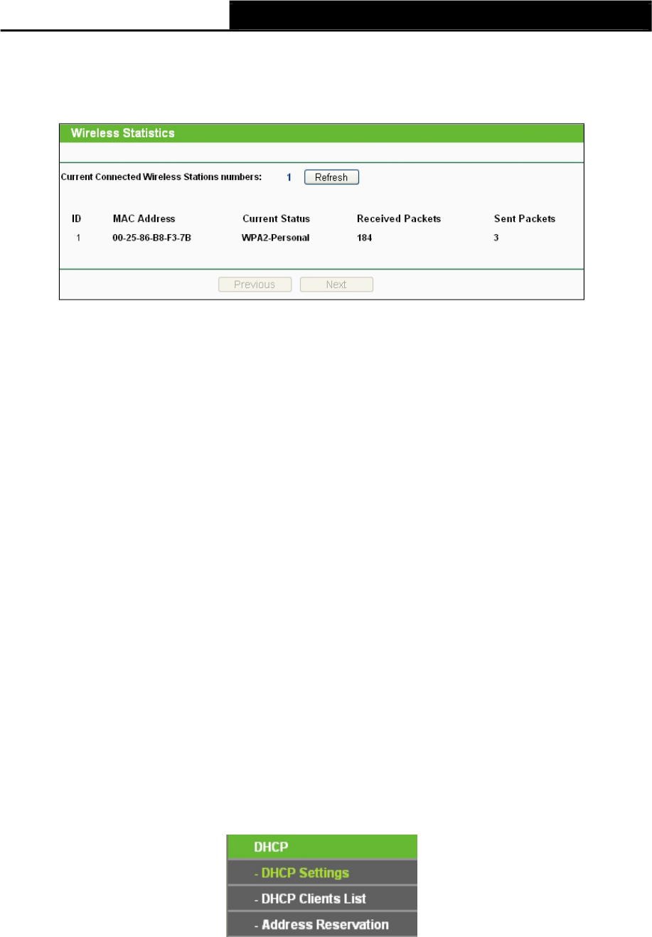
Figure 4-14 The router attached wireless stations
MAC Address - The connected wireless station's MAC address
Current Status - The connected wireless station's running status, one of STA-
AUTH / STA-ASSOC / AP-UP / WPA / WPA-PSK /WPA2/WPA2-PSK
Received Packets - Packets received by the station
Sent Packets - Packets sent by the station
You cannot change any of the values on this page. To update this page and to show the current
connected wireless stations, click on the Refresh button.
If the numbers of connected wireless stations go beyond one page, click the Next button to go to
the next page and click the Previous button to return the previous page.
Note:
This page will be refreshed automatically every 5 seconds.
4.8 DHCP
DHCP stands for Dynamic Host Configuration Protocol. The DHCP Server will
automatically assign dynamic IP addresses to the computers on the network. This protocol
simplifies network management and allows new wireless devices to receive IP addresses
automatically without the need to manually assign new IP addresses.
There are three submenus under the DHCP menu (shown as Figure 4-15): DHCP
Settings,DHCP Clients List and Address Reservation. Clicking any of them will enable you to
configure the corresponding function. The detailed explanations for each submenu are provided
below.
Figure 4-15 The DHCP menu
4.8.1 DHCP Settings
Selecting DHCP >DHCP Settings will enable you to set up the AP as a DHCP (Dynamic Host
Configuration Protocol) server, which provides the TCP/IP configuration for all the PCs that are
connected to the system on the LAN. The DHCP Server can be configured on the page (shown as
Figure 4-16).
53
TL-WA7110ND 150Mbps High Power Wireless Access Point User Guide
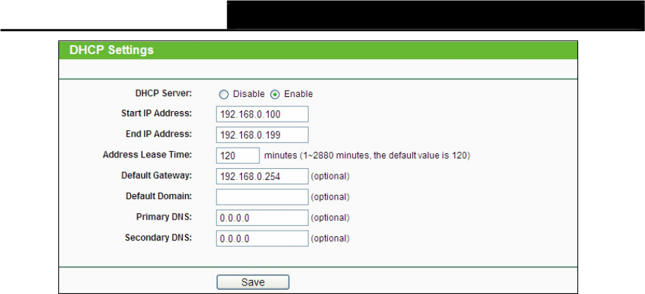
Figure 4-16 DHCP Settings
DHCP Server - Selecting the radio button before Disable/Enable will
disable/enable the DHCP server on your AP. The default setting is Disable. If you disable
the Server, you must have another DHCP server within your network or else you
must manually configure the computer.
Start IP Address - This field specifies the first address in the IP Address pool. 192.168.0.100
is the default start IP address.
End IP Address - This field specifies the last address in the IP Address pool. 192.168.0.199
is the default end IP address.
Address Lease Time - Enter the amount of time for the PC to connect to the AP with its
current assigned dynamic IP address. The time is measured in minutes. After the time is up,
the PC will be automatically assigned a new dynamic IP address. The range of the time is 1 ~
2880 minutes. The default value is 120 minutes.
Default Gateway (optional) - Enter the IP address of the gateway for your LAN. The factory
default setting is 0.0.0.0.
Default Domain (optional) - Enter the domain name of the your DHCP server.
You can leave the field blank.
Primary DNS (optional) - Enter the DNS IP address provided by your ISP. Consult your ISP
if you don’t know the DNS value. The factory default setting is 0.0.0.0.
Secondary DNS (optional) - Enter the IP address of another DNS server if
your ISP
provides two DNS servers. The factory default setting is 0.0.0.0.
Click Save to save the changes.
Note:
To use the DHCP server function of the device, you should configure all computers in the LAN as
"Obtain an IP Address automatically" mode. This function will not take effect until
the device reboots.
4.8.2 DHCP Clients List
Selecting DHCP >DHCP Clients List will enable you to view the Client Name,MAC Address,
Assigned IP and Lease Time for each DHCP Client attached to the device (Figure 4-17).
54
TL-WA7110ND 150Mbps High Power Wireless Access Point User Guide
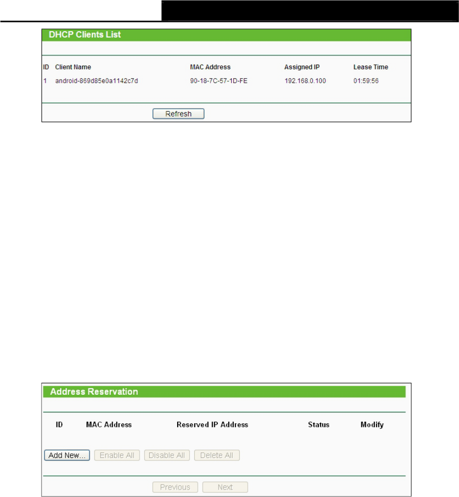
Figure 4-17 DHCP Clients List
ID - Here displays the index of the DHCP client.
Client Name - Here displays the name of the DHCP client.
MAC Address - Here displays the MAC address of the DHCP client.
Assigned IP - Here displays the IP address that the AP has allocated to the DHCP client.
Lease Time - Here displays the time of the DHCP client leased. Before the time is up, DHCP
client will request to renew the lease automatically.
You cannot change any of the values on this page. To update this page and to show the current
attached devices, click on the Refresh button.
4.8.3 Address Reservation
Selecting DHCP >Address Reservation will enable you to specify a reserved IP address for a
PC on the LAN, so the PC will always obtain the same IP address each time when it accesses the
AP. Reserved IP addresses should be assigned to servers that require permanent IP settings.
The screen below is used for address reservation (shown in Figure 4-18).
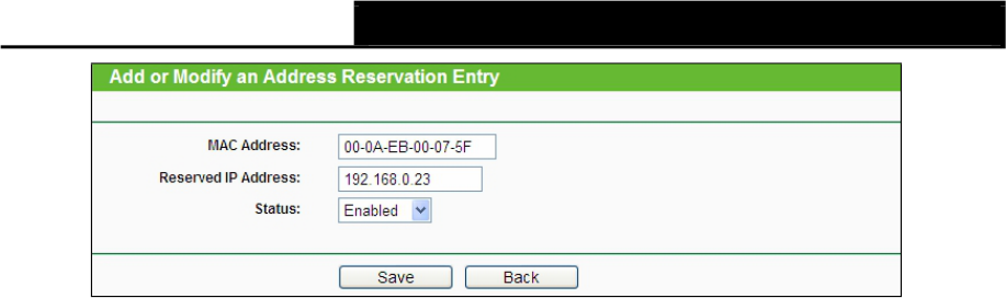
Figure 4-18 Address Reservation
MAC Address - Here displays the MAC address of the PC for which you want to reserve an
IP address.
Reserved IP Address - Here displays the IP address that the AP is reserved.
Status - Here shows whether the entry is enabled or not
Modify - To modify or delete an existing entry.
To Reserve IP addresses:
1. Click the Add New button in the page of Address Reservation, the following
page (Figure 4-19) will display.
2. Enter the MAC address (the format for the MAC Address is
XX-XX-XX-XX-XX-XX) and IP address in dotted-decimal notation
of the computer you want to add.
3. Click the Save button after finish configuring.
55
TL-WA7110ND 150Mbps High Power Wireless Access Point User Guide
Figure 4-19 Add or Modify an Address Reservation Entry
To modify A Reserved IP address:
1. Select the reserved address entry to your needs and click Modify. If you wish to delete the
entry, click Delete.
2. Click Save to keep your changes.
To delete all Reserved IP addresses:
Click Clear All.
Click Next to go to the next page and Click Previous to return the previous page.
Note:
The changes won't take effect until the device reboots.
4.9 System Tools
System Tools option helps you to optimize the configuration of your device. You can upgrade the
AP to the latest version of firmware as well as backup or restore the AP’s configuration files. Ping
Watch Dog can help to continuously monitor a particular connection to a remote host. Speed Test
helps to test the connection speed to and from any reachable IP address on current
network, especially when we are building wireless network between devices which are far away
from each other. It’s suggested that you change the default password to a more
secure one because it controls access to the device’s web-based management page.
Besides, you can find out what happened to the system in System Log.
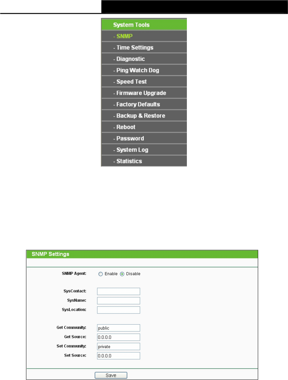
There are twelve submenus under the System Tools menu (shown as Figure 4-20): SNMP,Time
Settings,Diagnostic,Ping Watch Dog,Speed Test,Firmware Upgrade,Factory Defaults,
Backup & Restore,Reboot,Password,System log and Statistics. Clicking any of them will
enable you to configure the corresponding function. The detailed explanations for each submenu
are provided below.
56
TL-WA7110ND 150Mbps High Power Wireless Access Point User Guide
4.9.1
SNMP
Figure 4-20 The System Tools menu
Simple Network Management Protocol (SNMP) is a popular network monitoring and management
protocol.
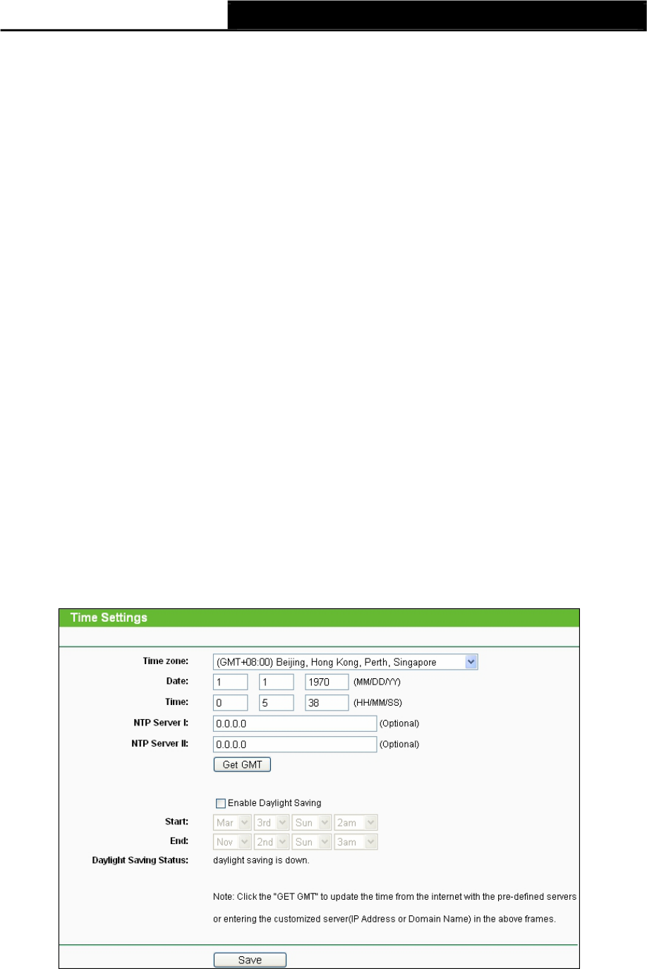
Choose menu “System Tools > SNMP”, and then you can configure the SNMP on the following
screen.
Figure 4-21
SNMP Agent - Choose Enable to open this function if you want to have remote control through
SNMPv1/v2 agent with MIB-II. Choose Disable to close this function.
SysContact - The textual identification of the contact person for this managed node.
SysName - An administratively-assigned name for this managed node.
SysLocation - The physical location of this node.
57
Note:
TL-WA7110ND 150Mbps High Power Wireless Access Point User Guide
Specifying one of these values via the Device's Web-Based Utility makes the
corresponding object read-only. If there isn't such a config setting, then the write request will
succeed (assuming suitable access control settings), but the new value would be forgotten the
next time the agent was restarted.
Get Community - Enter the community name that allows Read-Only access to the
Device's SNMP information. The community name can be considered a group
password. The default setting is public.
Get Source - Get source defines the IP address or subnet for management systems that can read
information from this 'get' community device.
Set Community - Enter the community name that allows Read/Write access to the
Device's SNMP information. The community name can be considered a group
password. The default setting is private.
Set Source - Set source defines the IP address or subnet for management systems
that can control this 'set' community device.
Note:
A restricted source can be a specific IP address (e.g. 10.10.10.1), or a subnet - represented as
IP/BITS (e.g. 10.10.10.0/24). If an IP Address of 0.0.0.0 is specified, the agent will
accept all requests under the corresponding community name.
Click the Save button to save your settings.
4.9.2 Time Settings
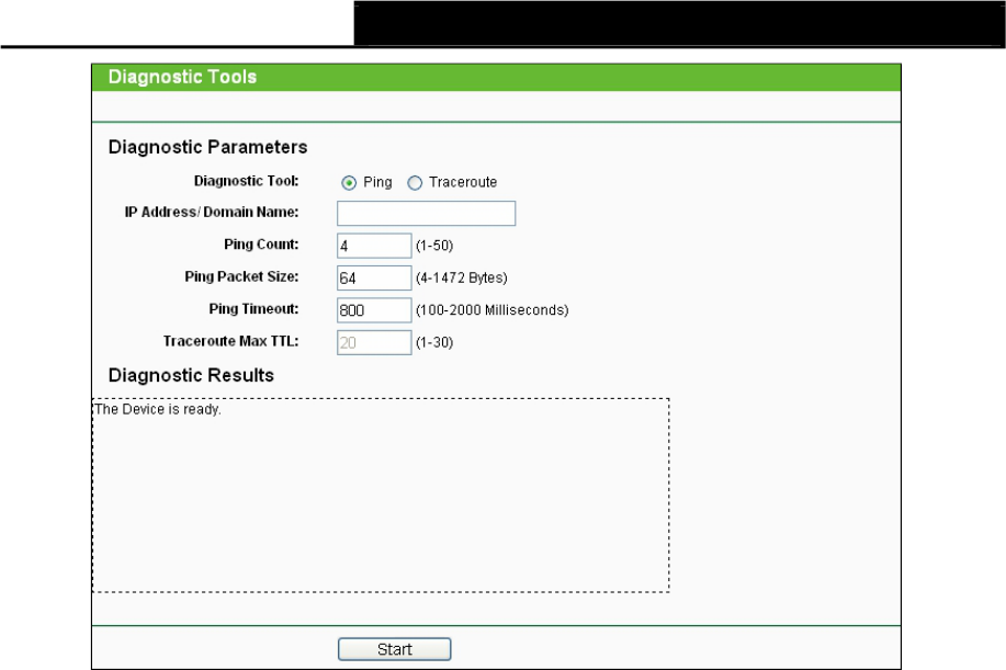
Choose menu “System Tools > Time Settings”, and then you can configure the time
on the following screen.
Figure 4-22 Time settings
Time Zone - Select your local time zone from this pull-down list.
To set time manually:
58

TL-WA7110ND 150Mbps High Power Wireless Access Point User Guide
1. Select your local time zone.
2. Enter the Date in Month/Day/Year format.
3. Enter the Time in Hour/Minute/Second format.
4. Click Save.
For automatic time synchronization:
1. Enter the address or domain of the NTP Server I or NTP Server II.
2. Click the Get GMT button to get GMT from the Internet.
To enable Daylight Saving:
1. Select the Enable Daylight Saving checkbox to enable daylight saving function.
2. Schedule the span of time which this function will effect. For example, if you want
this function work at 0 o'clock(am) on the 1st Sunday of April and last until at 6 o'clok(pm)
on the 2nd Saturday of September, you need choose "Apr", "1st", "Sun", "0am" at Start
part and choose "Sep", "2nd", "Sat", "6pm" at the End part.
3. Click the Save button to effect this function.
Note:
1) This setting will be used for some time-based functions such as firewall functions. These
time dependant functions will not work if time is not set. So, it is important to specify time
settings as soon as you successfully login to the Device.
2) The time will be lost if the Device is turned off.
3) The Device will automatically obtain GMT from the Internet if it is configured accordingly.
4) In daylight saving configuration, start time and end time shall be within one year and start
time shall be earlier than end time.
5) After you enable daylight saving function, it will take action in one minute.
4.9.3 Diagnostic
Choose menu “System Tools > Diagnostic”, and then you can transact Ping or
Traceroute function to check connectivity of your network in the following screen.
59
TL-WA7110ND 150Mbps High Power Wireless Access Point User Guide
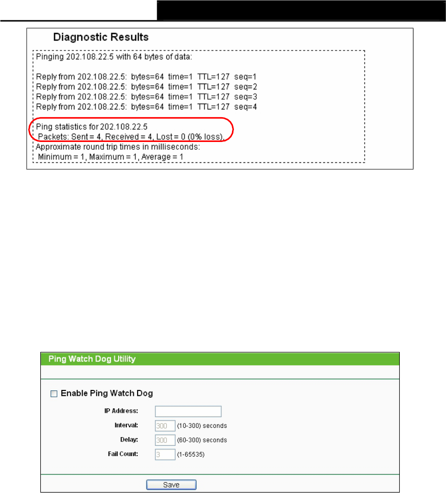
Figure 4-23 Diagnostic Tools
Diagnostic Tool - Click the radio button to select one diagnostic tool:
Ping - This diagnostic tool troubleshoots connectivity, reachability, and name resolution
to a given host or gateway.
Traceroute - This diagnostic tool tests the performance of a connection.
Note:
You can use ping/traceroute to test both numeric IP address or
domain name. If pinging/tracerouting the IP address is successful, but
pinging/tracerouting the domain name is not, you might have a name resolution problem. In
this case, ensure that the domain name you are specifying can be resolved by using Domain
Name System (DNS) queries.
IP Address/ Domain Name - Enter the IP Address or Domain Name of the
PC whose connection you wish to diagnose.
Ping Count - Specifies the number of Echo Request messages sent. The default is 4.
Ping Packet Size - Specifies the number of data bytes to be sent. The default is 64.
Ping Timeout - Time to wait for a response, in milliseconds. The default is 800.
Traceroute Max TTL - Set the maximum number of hops (max TTL to be reached) in the
path to search for the target (destination). The default is 20.
Click the Start button to start the diagnostic procedure.
The Diagnostic Results page (as shown in Figure 4-24) displays the result of diagnosis.
If the result is similar to the following screen, the connectivity of the Internet is fine.
60
TL-WA7110ND 150Mbps High Power Wireless Access Point User Guide
Note:
Figure 4-24 Diagnostic Results
1) Only one user can use the diagnostic tools at one time.
2) "Ping Count", "Ping Packet Size" and "Ping Timeout" are Ping Parameters, and "Traceroute
Max TTL" is Traceroute Parameter.
4.9.4 Ping Watch Dog
Selecting System Tools >Ping Watch Dog allows you to continuously monitor the
particular connection between the device to a remote host. It makes this device continuously
ping a user defined IP address (it can be the internet gateway for example). If it is unable to
ping under the user defined constraints, this device will automatically reboot.
Figure 4-25 Ping Watch Dog Utility
Enable Ping Watch Dog - Turn on/off Ping Watch Dog.
IP Address - The IP address of the target host where the Ping Watch Dog Utility is sending
ping packets.
Interval - Time internal between two ping packets which are sent out continuously.
Delay - Time delay before first ping packet is sent out when the device is restarted.
Fail Count - Upper limit of the ping packet the device can drop continuously. If this value is
overrun, the device will restart automatically.
Be sure to click the Submit button to make your settings in operation.
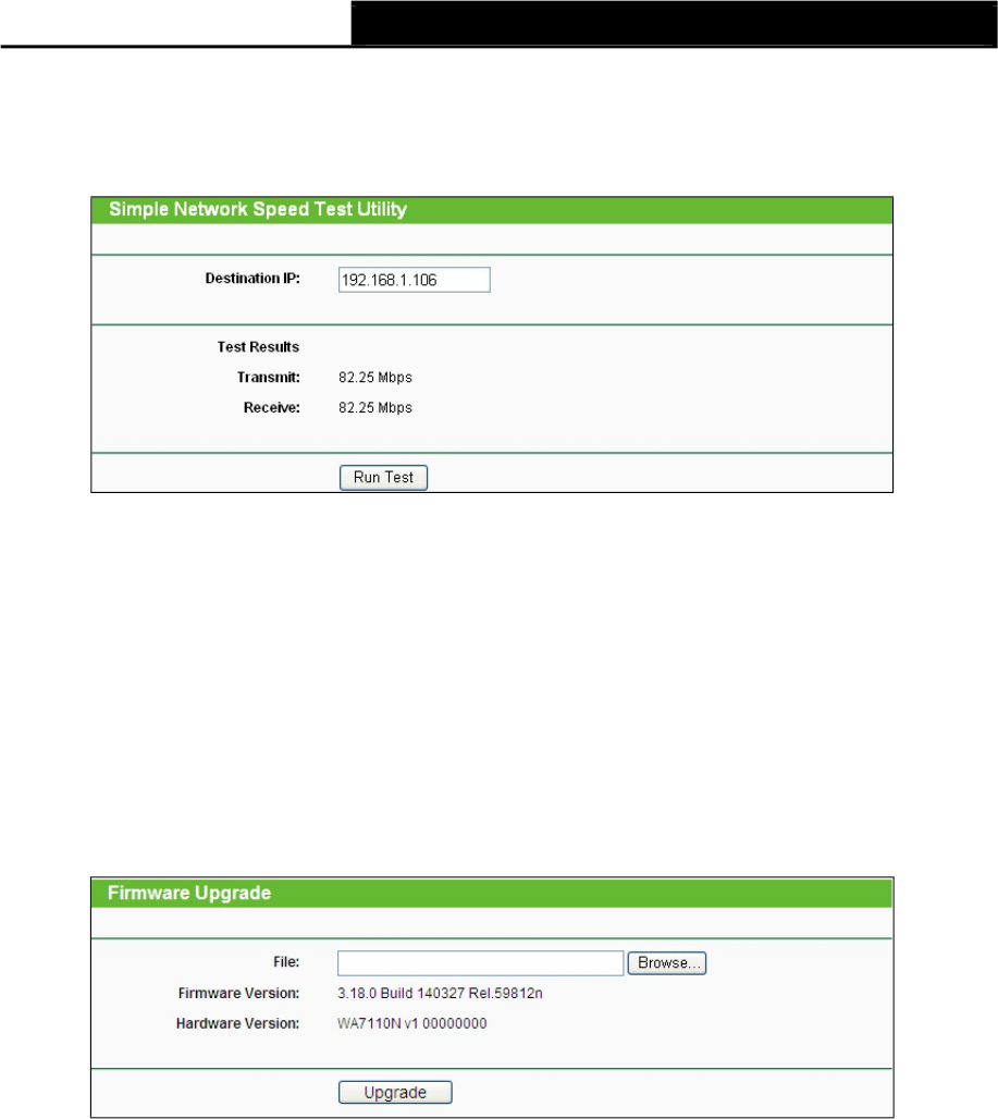
4.9.5 Speed Test
Selecting System > Speed Test allows you to test the connection speed to
and from any reachable IP address on current network on the page as shown in Figure 4-26.
The speed test is especially used when you are building wireless network between devices which
are far away from
61
TL-WA7110ND 150Mbps High Power Wireless Access Point User Guide
each other. It should be used for the preliminary throughput estimation between
two network devices. The estimation is rough. You can input the remote device's administrator
Username and Password under Advance options to get a precise estimation
if the remote device is TL-WA7110ND too.
Figure 4-26 Speed Test
Destination IP - The Remote device’s IP address.
Transmit - Estimate the outgoing throughput (Tx).
Receive - Estimate the ingoing throughput (Rx).
Be sure to click the Run Test button to start a new test after you filled enough information. You
can also stop a running test by click Stop Test button at any time.
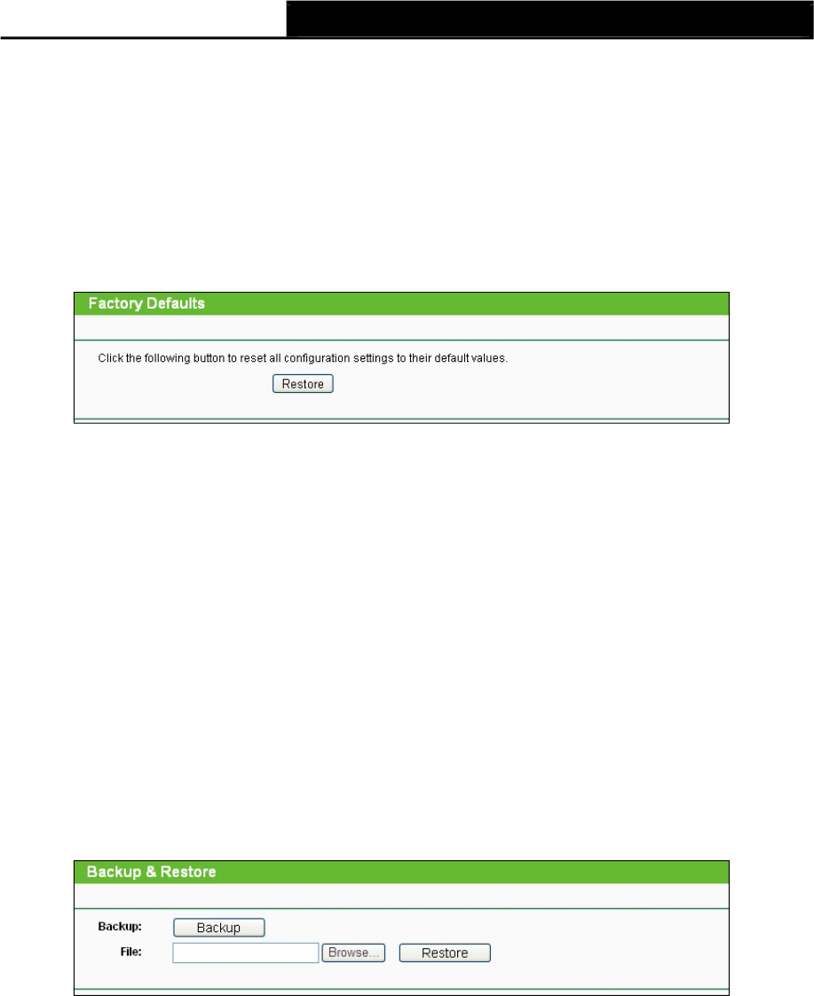
4.9.6 Firmware Upgrade
Choose menu System Tools > Firmware Upgrade, and then you can update the latest version
of firmware for the Device on the following screen.
Figure 4-27 Firmware Upgrade
To upgrade the Device's firmware, follow these instructions:
1. Download a most recent firmware upgrade file from our website (www.tp-link.com).
2. Enter or select the path name where you save the downloaded file on the computer into the
File Name blank.
3. Click the Upgrade button.
4. The Device will reboot while the upgrading has been finished.
Firmware Version - Displays the current firmware version.
Hardware Version - Displays the current hardware version. The hardware version
of the upgrade file must accord with the current hardware version.
62
Note:
TL-WA7110ND 150Mbps High Power Wireless Access Point User Guide
The firmware version must correspond to the hardware. The upgrade process
takes a few moments and the Device restarts automatically when the upgrade is complete. It
is important to keep power applied during the entire process. Loss of power during the upgrade
could damage the Device.
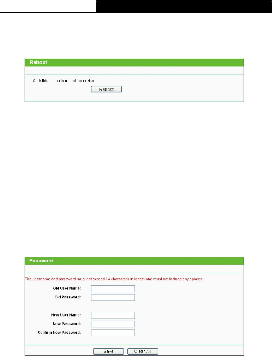
4.9.7 Factory Defaults
Choose menu System Tools > Factory Defaults, and you can restore the configurations of the
Device to factory defaults on the following screen.
Figure 4-28 Restore Factory Default
Click the Restore button to reset all configuration settings to their default values.
Default User Name - admin.
Default Password - admin.
Default IP Address - 192.168.0.254.
Default Subnet Mask - 255.255.255.0.
Note:
All changed settings will be lost when defaults are restored.
4.9.8 Backup & Restore
Choose menu “System Tools > Backup & Restore”, and then you can save
the current configuration of the Device as a backup file and restore the configuration via a
backup file as shown in Figure 4-29.
Figure 4-29 Backup & Restore
Click the Backup button to save all configuration settings to your local computer as a file.
To restore the AP's configuration, follow these instructions:
1. Click the Browse button to find the configuration file which you want to restore.
2. Click the Restore button to update the configuration with the file whose path is the one you
have input or selected in the blank.
Note:
The current configuration will be covered with the uploading configuration file. Wrong process will
lead the device unmanaged. The restoring process lasts for 20 seconds and the AP will restart
automatically then. Keep the power of the AP on during the process, in case of any damage.
63
4.9.9
Reboot
TL-WA7110ND 150Mbps High Power Wireless Access Point User Guide
Choose menu System Tools > Reboot, and then you can click the Reboot button to reboot the
Device via the next screen.
Figure 4-30 Reboot the Device
Click the Reboot button to reboot the Device.
Some settings of the Device will take effect only after rebooting, including:
Change the LAN IP Address (system will reboot automatically).
Change the DHCP Settings.
Change the Wireless configurations.
Change the Web Management Port.
Upgrade the firmware of the Device (system will reboot automatically.).
Restore the Device's settings to the factory defaults (system will reboot automatically.).
Update the configuration with the file (system will reboot automatically.).
4.9.10 Password
Choose menu System Tools > Password, and then you can change the factory default user
name and password of the Device in the next screen as shown in Figure 4-31.
Figure 4-31 Password
It is strongly recommended that you change the factory default user name and password of the
AP. All users who try to access the AP's web-based utility will be prompted for the AP's user name
and password.
Note:
The new user name and password must not exceed 14 characters in length and must not include
any spaces. Enter the new Password twice to confirm it.
Click the Save button when finished.
Click the Clear All button to clear all.
64

TL-WA7110ND 150Mbps High Power Wireless Access Point User Guide
4.9.11 System log
Choose menu System Tools > System Log, and then you can view the logs of the Device.
Figure 4-32 System Log
Auto Mail Feature - Indicates whether auto mail feature is enabled or not.
Mail Settings - Set the receiving and sending mailbox address, server address, validation
information as well as the timetable for Auto Mail Feature.
Figure 4-33 Mail Account Settings
From - Your mail box address.
To - Recipient's address.
SMTP Server - Your SMTP server.
Authentication - Most SMTP Server requires Authentication.
65
Note:
TL-WA7110ND 150Mbps High Power Wireless Access Point User Guide
Only when you select Authentication, do you have to enter the User Name and Password in
the following fields.
User Name - Your mail account name.
Password - Your mail account password.
Auto Mail Feature will help you monitor how your Device is running.
Everyday, at specified time, the Device will automatically send the log to specified mailbox.
Every few hours, such as 2 hours, the Device will automatically send the log to specified mailbox.
Log Type - By selecting the log type, only logs of this type will be shown.
Log Level - By selecting the log level, only logs of this level will be shown.
Refresh - Refresh the page to show the latest log list.
Save Log - Click to save all the logs in a txt file.
Mail Log - Click to send an email of current logs manually according to the
address and validation information set in Mail Settings. The result will be shown in the later log
soon.
Clear Log - All the logs will be deleted from the Device permanently, not just from the page.
Click the Next button to go to the next page.
Click the Previous button return to the previous page.
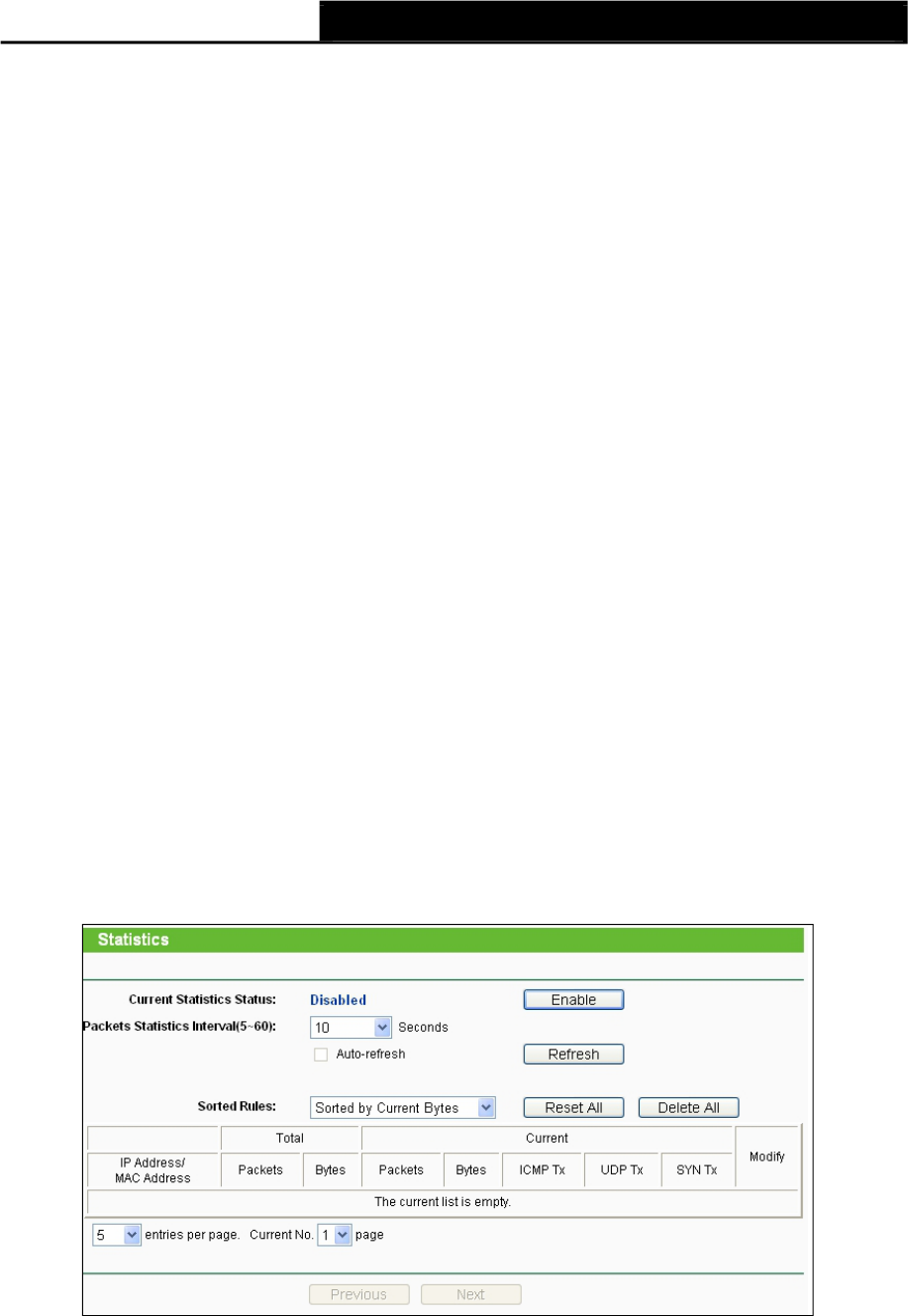
4.9.12 Statistics
Choose menu System Tools > Statistics, and then you can view the statistics of the Device,
including total traffic and current traffic of the last Packets Statistic Interval.
Figure 4-34 Statistics
The Statistics page shows the network traffic of each PC on the LAN, including total traffic and the
value of the last Packets Statistic interval in seconds.
Current Statistics Status - Enabled or Disabled. The default value is disabled. To enable,
click the Enable button. If disabled, the function of DoS protection in Security settings will be
disabled.
66
TL-WA7110ND 150Mbps High Power Wireless Access Point User Guide
Packets Statistics Interval - The default value is 10. Select a value between
5 and 60 seconds in the pull-down list. The Packets Statistic interval value indicates the
time section of the packets statistic.
Sorted Rules - Choose how displayed statistics are sorted.
Click the Auto-refresh checkbox to refresh automatically.
Click the Refresh button to refresh the page.
Click the Reset All button to reset the values of all entries to zero.
Click the Delete All button to delete all entries in the table.
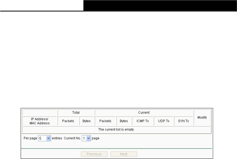
Statistics Table
Figure 4-35 Statistics Table
IP Address/MAC Address - The IP Address and MAC address are displayed with related
statistics.
Total
Packets - The total number of packets received and transmitted by the Device.
Bytes - The total number of bytes received and transmitted by the Device.
Current
Packets - The total number of packets received and transmitted in the
last Packets
Statistics interval seconds.
Bytes - The total number of bytes received and transmitted in the last Packets Statistics
interval seconds.
ICMP Tx - The number of ICMP packets transmitted to the WAN per
second at the specified Packets Statistics interval. It is shown like "current
transmitting rate / Max transmitting rate".
UDP Tx - The number of UDP packets transmitted to the WAN per second at the
specified Packets Statistics interval. It is shown like "current transmitting rate /
Max transmitting rate".
TCP SYN Tx - The number of TCP SYN packets transmitted to the WAN per second
at the specified Packets Statistics interval. It is shown like "current transmitting rate /
Max transmitting rate".
Modify
Reset - Reset the values of the entry to zero.
Delete - Delete the existing entry in the table.
67

TL-WA7110ND 150Mbps High Power Wireless Access Point User Guide
Chapter 5. AP Client Router & AP Router Operation Mode
This Chapter describes how to configure some advanced settings for your Access Point through
the web-based management page. In the following explanations, we will take the device in AP
Client Router operation mode for example.
5.1 Login
After your successful login, you can configure and manage the Access Point. There are fifteen
main menus on the left of the Web-based management page. Submenus will be available after
you click one of the main menus. The sixteen main menus are: Status,Quick Setup,Operation
Mode,WPS,Network,Wireless,DHCP,Forwarding,Security,Parental Control,
Access Control,Advanced Routing,Bandwidth Control,IP & MAC Binding,
Dynamic DNS and System Tools. On the right of the Web-based management
page, there are the detailed explanations and instructions for the corresponding page. To
apply any settings you have altered
on the page, please click Save.
The detailed explanations for each Web page key’s function are listed below.
5.2 Status
Selecting Status will enable you to view the AP’s current status and configuration, all of which is
read-only.
68

TL-WA7110ND 150Mbps High Power Wireless Access Point User Guide
1. LAN
Figure 5-1 Status
This field displays the current settings or information for the LAN, including the MAC address,IP
address and Subnet Mask.
2. Wireless
This field displays basic information or status for wireless function, including Wireless
Radio,
Name (SSID),Channel,Mode,Channel Width,MAC address and Client Status.
3. WAN
These parameters apply to the WAN port of the router, including MAC address,IP
address,Subnet Mask,Default Gateway and DNS server. If PPPoE is chosen as the WAN
connection type, the Disconnect button will be shown here while you are accessing the
Internet. You can also cut the connection by clicking the button. If you have not connected to the
Internet, just click Connect to establish the connection.
69
TL-WA7110ND 150Mbps High Power Wireless Access Point User Guide
4. Traffic Statistics
This field displays the router's traffic statistics.
5. System Up Time
The total up time of the router since it was powered on or reset.
5.3 Quick Setup
Please refer to Section 3.2: "Quick Setup".
5.4 Operation Mode
Selecting Operation Mode will allow you to choose the operation mode for the
AP. The AP supports seven operation mode types, AP Client Router,AP Router,Access
Point,Multi-SSID,Repeater (Range Extender),Bridge with AP and Client. Please select
the one your want as shown in Figure 4-2. Click Save to save your choice.
Figure 5-2 Operation Mode
AP Client Router - In this mode, the device enables multi-users to share Internet from WISP.
The LAN port devices share the same IP from WISP through Wireless port. While connecting
to WISP, the Wireless port works as a WAN port at AP Client Router mode. The Ethernet
port acts as a LAN port.
AP Router - In this mode, the device enables multi-users to share Internet via ADSL/Cable
Modem. The wireless port share the same IP to ISP through Ethernet WAN
port. The Wireless port acts the same as a LAN port while at AP Router mode.
Access Point - In this mode, the device can be connected to a wired network and transform
the wired access into wireless that multiple devices can share together,
especially for a home, office or hotel where only wired network is available.
Multi-SSID - In this mode, the device can create up to 4 wireless networks
labeled with different SSIDs and assign each SSID with different security or
VLAN, especially for the situation when the various access policies and functions are
required.
Repeater(Range Extender) - In this mode, the device can copy and reinforce the existing
wireless signal to extend the coverage of the signal, especially for a large space to eliminate
signal-blind corners.
Bridge with AP - In this mode, the device can be used to combine multiple local networks
together to the same one via wireless connections, especially for a home or office where
separated networks can't be connected easily together with a cable.
70
TL-WA7110ND 150Mbps High Power Wireless Access Point User Guide
Client - In this mode, the device can be connected to another device via Ethernet port and
act as an adaptor to grant your wired devices access to a wireless network, especially for a
Smart TV, Media Player, or game console only with an Ethernet port.
Note:
When you change the operation mode to Client/Repeater, WPS function will stay disabled. Please
manually enable this function if needed when you switch back to Access Point/Multi-SSID/Bridge
mode.
5.5 WPS
WPS function will help you add a new device to the network quickly. If the new device supports
Wi-Fi Protected Setup and is equipped with a configuration button, you can add it to the network
by pressing the configuration button on the device and then press the button on the device within
two minutes. The status LED on the device will light green for five minutes if the device has been
successfully added to the network. If the new device supports Wi-Fi Protected Setup
and the connection way using PIN, you can add it to the network by entering the device's PIN.
Select menu WPS, then you will see the next screen (shown in Figure 5-3 ).
Figure 5-3
WPS Status - Enable or disable the WPS function here.
Current PIN - The current value of the Device's PIN displayed here. The default PIN of the
Device can be found in the label or User Guide.
Restore PIN - Restore the PIN of the Device to its default.
Gen New PIN - Click this button, and then you can get a new random value for the Device's
PIN. You can ensure the network security by generating a new PIN.
Add A New Device - You can add the new device to the existing network
manually by clicking Add Device button.
Note:
The WPS function cannot be configured if the Wireless Function of the Device is disabled. Please
make sure the Wireless Function is enabled before configuring the WPS.
To add a new device:
If the wireless adapter supports Wi-Fi Protected Setup (WPS), you can establish
a wireless connection between wireless adapter and Router using either Push Button
Configuration (PBC) method or PIN method.
Note:
To build a successful connection by WPS, you should also do the corresponding configuration of
the new device for function meanwhile.
71
TL-WA7110ND 150Mbps High Power Wireless Access Point User Guide
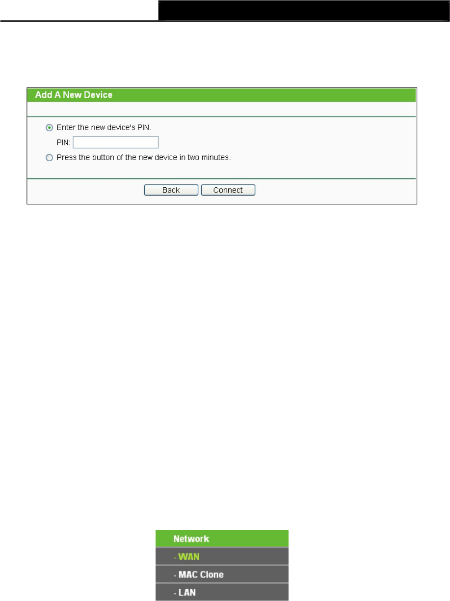
I. Enter the client device’s PIN on the Router
Use this method if your client device has a Wi-Fi Protected Setup PIN number.
Step 1: Keep the default Status as Enabled and click the Add Device button in Figure 5-3,
then the following screen will appear.
Figure 5-4 Add A New Device
Step 2: Enter the PIN number from the client device in the field on the above WPS screen. Then
click Connect button.
Step 3: “Connect successfully” will appear on the screen of Figure 5-4, which means the client
device has successfully connected to the Router.
II. Enter the Router’s PIN on your client device
Use this method if your client device asks for the Router’s PIN number.
Step 1: On the client device, enter the PIN number listed on the Router’s Wi-Fi Protected Setup
screen. (It is also labeled on the bottom of the Router.)
Step 2: The Wi-Fi Protected Setup LED flashes for two minutes during the Wi-Fi
Protected
Setup process.
Step 3: When the WPS LED is on, the client device has successfully connected to the Router.
Step 4: Refer back to your client device or its documentation for further instructions.
5.6 Network
The Network option allows you to customize your local network manually by changing the default
settings of the AP.
There are three submenus under the Network menu (shown in Figure 5-5): LAN,WAN and MAC
Clone. Click any of them, and you will be able to configure the corresponding
function. The detailed explanations for each submenu are provided below.
5.6.1 WAN
Figure 5-5 the Network menu
Choose menu Network >WAN, and then you can configure the IP parameters of the WAN on the
screen below. There are six WAN connection types: Dynamic IP, Static IP, PPPoE/Russia PPPoE,
BigPond Cable, L2TP/Russia L2TP, and PPTP/Russia PPTP; while there is one more type in AP
Router mode, BigPond Cable.
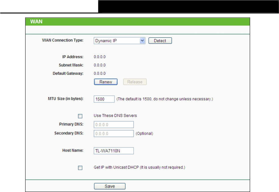
1. If your ISP is running a DHCP server, select the Dynamic IP option. Then the Device will
automatically get IP parameters from your ISP. You can see the page as follow (Figure 5-6).
72
TL-WA7110ND 150Mbps High Power Wireless Access Point User Guide
Figure 5-6 WAN – Dynamic IP
This page displays the WAN IP parameters assigned dynamically by your ISP,
including IP
address, Subnet Mask, Default Gateway, etc.
IP Address - The IP address assigned by your ISP dynamically.
Subnet Mask - The subnet mask assigned by your ISP dynamically.
Default Gateway - The default gateway assigned dynamically by your ISP.
MTU Size (in bytes) - The normal MTU (Maximum Transmission Unit)
value for most Ethernet networks is 1500 Bytes. For some ISPs you need to modify the
MTU. But this is rarely required, and should not be done unless you are sure it
is necessary for your ISP connection.
If your ISP gives you one or two DNS IP addresses, select Use These DNS Servers and enter
the Primary DNS and Secondary DNS into the correct fields. Otherwise, the DNS servers will be
assigned from ISP dynamically.
Primary DNS - Enter the DNS IP address in dotted-decimal notation provided by your ISP.
Secondary DNS - Enter another DNS IP address in dotted-decimal notation provided by your
ISP.
Click the Renew button to renew the IP parameters from your ISP.
Click the Release button to release the IP parameters.
Note:
If you get Address not found error when you access a Web site, it is likely that your DNS servers
are set up improperly. You should contact your ISP to get DNS server addresses.
Get IP with Unicast DHCP - A few ISPs' DHCP servers do not support
the broadcast applications. If you can't get the IP Address normally, you can choose
Unicast. You generally need not to check this option.
73
TL-WA7110ND 150Mbps High Power Wireless Access Point User Guide
Click the Save button to save your settings.
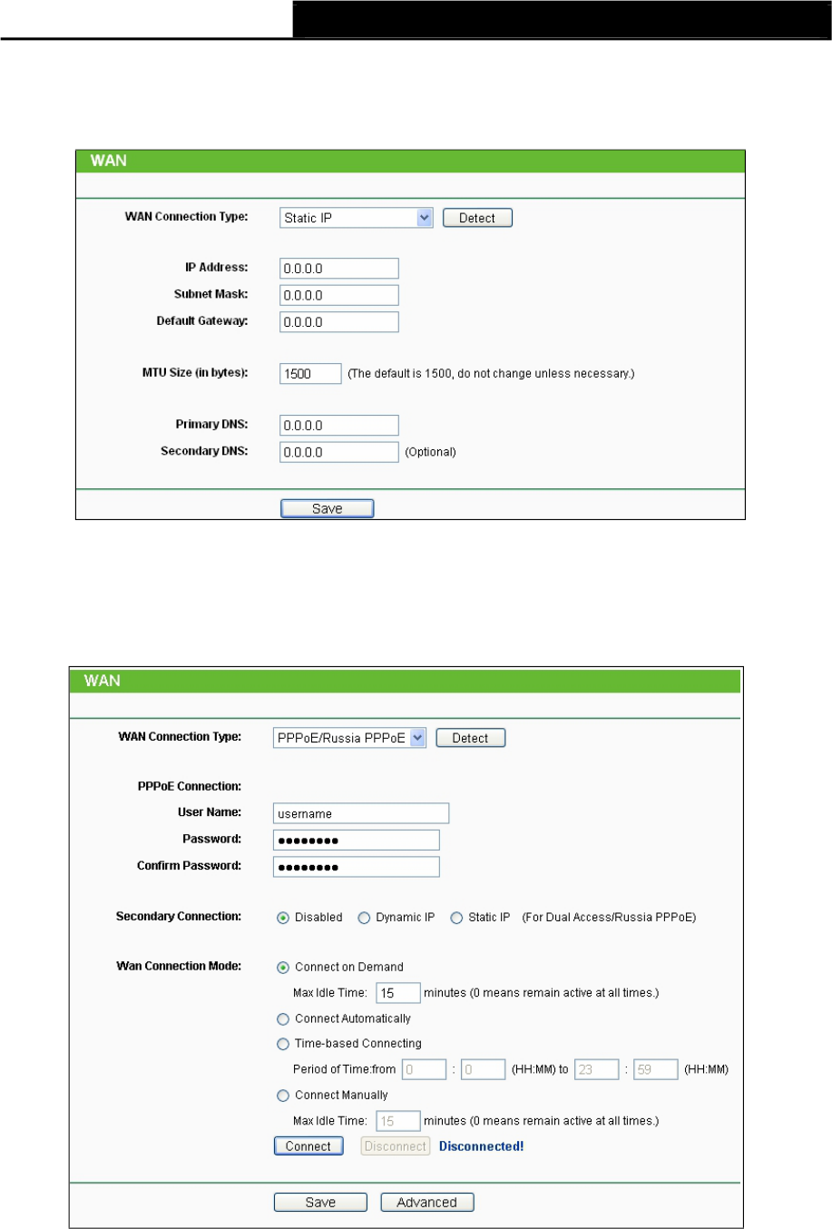
2. If your ISP provides a static or fixed IP Address, Subnet Mask, Gateway and DNS setting,
select the Static IP option. The Static IP settings page will appear as shown in Figure 5-7.
Figure 5-7 WAN - Static IP
Click the Save button to save your settings.
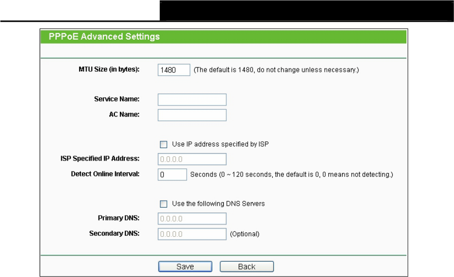
3. If your ISP provides a PPPoE connection, select PPPoE/Russia PPPoE option. Then you
should enter the following parameters (Figure 5-8):
PPPoE Connection
Figure 5-8 WAN – PPPoE/Russia PPPoE
User Name/Password - Enter the User Name and Password provided by
your ISP. These fields are case-sensitive.
74

TL-WA7110ND 150Mbps High Power Wireless Access Point User Guide
Secondary Connection - It's available only for PPPoE Connection. If your ISP provides an
extra Connection type such as Dynamic/Static IP to connect to a local area network, then you
can check the radio button of Dynamic/Static IP to activate this secondary connection.
Disabled - The Secondary Connection is disabled by default, so there
is PPPoE
connection only. This is recommended.
Dynamic IP - Use dynamic IP address to connect to the local area network provided by
ISP.
Static IP - Use static IP address to connect to the local area network provided by ISP.
WAN Connection Mode
Connect on Demand - You can configure the Device to disconnect
your Internet connection after a specified period of the Internet connectivity (Max Idle
Time). If your Internet connection has been terminated due to inactivity, Connect on
Demand enables the Device to automatically re-establish your connection when you
attempt to access the Internet again. If you wish to activate Connect on Demand, put a
check mark in the circle.
If you want your Internet connection to remain active all the time, enter 0in the Max Idle
Time field.
Note:
Sometimes the connection cannot be disconnected although you specify a time to Max Idle
Time (0~99 mins) because some applications visit the Internet continually in the background.
Connect Automatically - Connect automatically after the Device is disconnected. To use
this option, click the radio button.
Time-based Connecting - You can configure the Device to make
it connect or disconnect based on time. Enter the start time in HH-MM for
connecting and end time in HH-MM for disconnecting in the Period of Time fields.
Connect Manually - You can configure the Device to make it connect or
disconnect manually. After a specified period of inactivity (Max Idle
Time), the Device will disconnect your Internet connection, and not be able
to re-establish your connection automatically as soon as you attempt to access the
Internet again. To use this option, click the radio button. If you want your Internet
connection to remain active all the times, enter 0 in the Max Idle Time field.
Otherwise, enter the number in minutes that you wish to have the Internet connecting
last unless a new link is requested.
Note:
1) Sometimes the connection cannot be disconnected although you specify a
Max Idle Time (0~99 mins) because some applications visit the Internet
continually in the background.
2) Only when you have set the system time on System Tools →Time Settings page, the
Time-based Connecting function can take effect.
Click the Connect button to connect immediately.
Click the Disconnect button to disconnect immediately.
Click the Advanced button to set up the advanced options.
Click the Save button to save your settings.
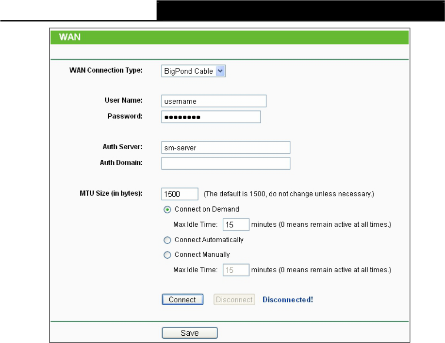
If you want to do some advanced configurations, please click the Advanced button, and then
the page shown in Figure 5-9 will appear.
75
TL-WA7110ND 150Mbps High Power Wireless Access Point User Guide
Figure 5-9 PPPoE Advanced Settings
MTU Size - The default MTU (Maximum Transmission Unit) size is 1480 bytes,
which is usually fine. For some ISPs, you need modify the MTU. This should not be done
unless you are sure it is necessary for your ISP.
Service Name/AC Name - They should not be done unless you are sure it is necessary for
your ISP.
ISP Specified IP Address - If you know that your ISP does not automatically transmit IP
address to the Device during login, click "Use the IP Address specified by ISP" checkbutton
and enter the IP address in dotted-decimal notation, which is provided by your ISP.
Detect Online Interval - The default value is 0. You can input the value between 0 and 120.
The Device will detect Access Concentrator online every interval seconds. If the value is 0, it
means not detecting.
Use the following DNS Servers - If your ISP specifies a DNS server IP address for you,
click the checkbox, and fill the Primary DNS and Secondary DNS blanks
below. The Secondary DNS is optional. Otherwise, the DNS servers will be assigned
dynamically from ISP.
Primary DNS - (Optional) Enter the DNS IP address in dotted-decimal notation provided by
your ISP.
Secondary DNS - (Optional) Enter another DNS IP address in dotted-decimal
notation provided by your ISP.
Note:
The new advanced PPPoE parameters will not take effect until you dial-up again.
Click the Save button to save your settings.
Click the Back button when finished.
4. If your ISP provides BigPond Cable (or Heart Beat Signal) connection, please select BigPond
Cable option. And then you should enter the following parameters as in Figure 5-10.
76
TL-WA7110ND 150Mbps High Power Wireless Access Point User Guide
Figure 5-10 WAN – BigPond Cable
User Name/Password - Enter the User Name and Password provided by your ISP. These
fields are case-sensitive.
Auth Server - Enter the authenticating server IP address or host name.
Auth Domain - Type in the domain suffix server name based on your location.
NSW / ACT - nsw.bigpond.net.au
VIC / TAS / WA / SA / NT - vic.bigpond.net.au
QLD - qld.bigpond.net.au
MTU Size - The normal MTU (Maximum Transmission Unit) value for most Ethernet networks
is 1500 Bytes. It is not recommended that you change the default MTU Size unless required
by your ISP.
Connect on Demand - In this mode, the Internet connection can be terminated automatically
after a specified inactivity period (Max Idle Time) and be re-established when you attempt to
access the Internet again. If you want your Internet connection keeps active all
the time, please enter “0” in the Max Idle Time field. Otherwise, enter the number of
minutes you want
to have elapsed before your Internet access disconnects.
Connect Automatically - The connection can be re-established automatically when it was
down.
Connect Manually - You can click the Connect/Disconnect button to connect/disconnect
immediately. This mode also supports the Max Idle Time function as Connect on Demand
mode. The Internet connection can be disconnected automatically after a specified inactivity
period and re-established when you attempt to access the Internet again.
Click the Connect button to connect immediately. Click the Disconnect button to disconnect
immediately.
77
Note:
TL-WA7110ND 150Mbps High Power Wireless Access Point User Guide
Sometimes the connection cannot be terminated although you specify a time to Max Idle Time
because some applications are visiting the Internet continually in the background.
Click the Save button to save your settings.
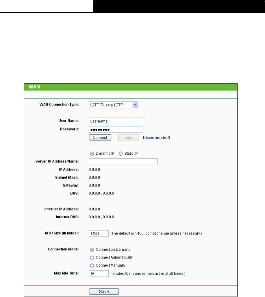
5. If your ISP provides L2TP connection, please select L2TP/Russia L2TP option. Then you
should enter the following parameters in Figure 5-11.
Figure 5-11 WAN – L2TP/Russia L2TP
User Name/Password - Enter the User Name and Password provided by your ISP. These
fields are case-sensitive.
Dynamic IP/ Static IP - Choose either one as you are given by your ISP. Click the Connect
button to connect immediately. Click the Disconnect button to disconnect immediately.
Connect on Demand - You can configure the Device to disconnect from
your Internet connection after a specified period of inactivity (Max Idle Time). If your
Internet connection has been terminated due to inactivity, Connect on
Demand enables the Device to automatically re-establish your connection as
soon as you attempt to access the Internet again. If you wish to activate Connect on
Demand, check the radio button. If you want your Internet connection to remain active at all
time, enter 0 in the Max Idle Time field. Otherwise, enter the number of minutes you
want to have elapsed before your Internet connection terminates.
Connect Automatically - Connect automatically after the Device is disconnected. To use
this option, check the radio button.
78
TL-WA7110ND 150Mbps High Power Wireless Access Point User Guide
Connect Manually - You can configure the Device to make it connect
or disconnect manually. After a specified period of inactivity (Max Idle Time), the Device
will disconnect from your Internet connection, and you will not be able to re-
establish your connection automatically as soon as you attempt to access the Internet
again. To use this option, check the radio button. If you want your Internet connection to
remain active at all time, enter "0" in the Max Idle Time field. Otherwise, enter the number
of minutes that you wish to have the Internet connecting last unless a new link is requested.
Note:
Sometimes the connection cannot be disconnected although you specify a time to Max Idle Time,
because some applications are visiting the Internet continually in the background.
Click the Save button to save your settings.
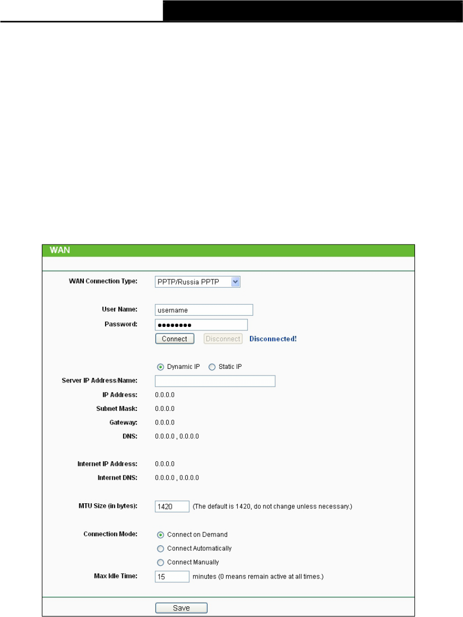
6. If your ISP provides PPTP connection, please select PPTP/Russia PPTP option. And you
should enter the following parameters (Figure 5-12):
Figure 5-12 WAN – PPTP/Russia PPTP
User Name/Password - Enter the User Name and Password provided by your ISP. These
fields are case-sensitive.
Dynamic IP/ Static IP - Choose either as you are given by your ISP and enter the ISP’s IP
address or the domain name.
If you choose static IP and enter the domain name, you should also enter
the DNS
assigned by your ISP. And click the Save button.
Click the Connect button to connect immediately. Click the Disconnect
button to disconnect immediately.
79

TL-WA7110ND 150Mbps High Power Wireless Access Point User Guide
Connect on Demand - You can configure the Device to disconnect from
your Internet connection after a specified period of inactivity (Max Idle Time). If your
Internet connection has been terminated due to inactivity, Connect on
Demand enables the Device to automatically re-establish your connection as
soon as you attempt to access the Internet again. If you wish to activate Connect on
Demand, check the radio button. If you want your Internet connection to remain active
at all times, enter “0” in the Max Idle Time field. Otherwise, enter the
number of minutes you want to have elapsed before your Internet connection
terminates.
Connect Automatically - Connect automatically after the Device is disconnected. To use
this option, check the radio button.
Connect Manually - You can configure the Device to make it connect
or disconnect manually. After a specified period of inactivity (Max Idle Time), the Device
will disconnect from your Internet connection, and you will not be able to re-
establish your connection automatically as soon as you attempt to access the Internet
again. To use this option, click the radio button. If you want your Internet connection to
remain active at all times, enter "0" in the Max Idle Time field. Otherwise, enter the number
in minutes that you wish to have the Internet connecting last unless a new link is requested.
Note:
Sometimes the connection cannot be disconnected although you specify a time to Max Idle Time
because some applications are visiting the Internet continually in the background.
Click the Save button to save your settings.
5.6.2 MAC Clone
MAC Clone allows you to clone the MAC address of the managing PC’s adapter to the WAN port.
This is because some ISPs require that you register the MAC address of your adapter. Usually,
you do not need to change anything here.
Selecting Network > MAC Clone will enable you to configure the MAC address of the WAN port
on this page as shown in Figure 5-13.
Figure 5-13 MAC Address Clone
Some ISPs require that you register the MAC Address of your adapter, which is connected to your
cable/DSL Modem or Ethernet during installation. Changes are rarely needed here.
WAN MAC Address - This field displays the current MAC address of the WAN port, which is
used for the WAN port. If your ISP requires that you register the MAC address, please enter
the correct MAC address into this field. The format for the
MAC Address is XX-XX-XX-XX-XX-XX (X is any hexadecimal digit).
Your PC's MAC Address - This field displays the MAC address of the PC that is managing
the router. If the MAC address is required, you can click the Clone MAC Address button and
this MAC address will fill in the WAN MAC Address field.
Click Restore Factory MAC to restore the MAC address of WAN port to the factory default value.
80
TL-WA7110ND 150Mbps High Power Wireless Access Point User Guide
Click Save to save your settings.
Note:
1) Only the PC on your LAN can use the Clone MAC Address feature.
2) If you click Save, the Router will prompt you to reboot.
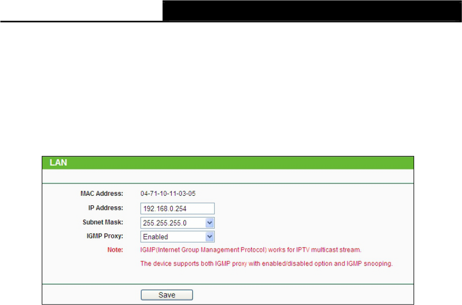
5.6.3 LAN
Selecting Network > LAN will enable you to configure the IP parameters of LAN port on this page.
Figure 5-14 LAN
MAC Address - The physical address of the router, as seen from the LAN. The value can't
be changed.
IP Address - Enter the IP address of your router in dotted-decimal notation (factory default:
192.168.0.254).
Subnet Mask - An address code that determines the size of the network.
Normally use
255.255.255.0 as the subnet mask.
IGMP Proxy – IGMP (Internet Group Management Protocol) works for IPTV multicast stream.
The device supports both IGMP proxy with enabled/disabled option and IGMP snooping.
Note:
1) If you change the IP Address of LAN, you must use the new IP Address to login the Router.
2) If the new LAN IP Address you set is not in the same subnet, the IP Address pool of the DHCP
server will not take effect until they are re-configured.
3) If the new LAN IP Address you set is not in the same subnet, the Virtual Server and DMZ Host
will change accordingly at the same time.
5.7 Wireless
The Wireless option, improving functionality and performance for wireless network, can help you
to make the AP an ideal solution for your wireless network.
Here you can create a wireless local area network just through a few settings. Basic Settings is
used for the configuration of some basic parameters of the AP. Wireless Mode
allows you to select the mode that AP works on. Security Settings provides three
different security types to secure your data and thus provide greater security for your wireless
network. MAC filtering allows you to control the access of wireless stations to the
AP. Wireless Statistics shows you the statistics of current connected Wireless stations.
Distance Setting is used to adjust the wireless range in outdoor conditions. Throughput Monitor
helps to watch wireless throughput information Wireless statistics enables you to get detailed
information about the current connected wireless stations.
81
TL-WA7110ND 150Mbps High Power Wireless Access Point User Guide
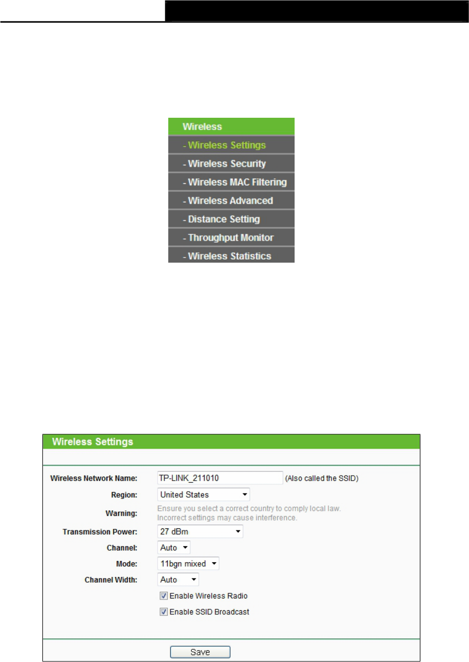
There are eight submenus under the Wireless menu (shown in Figure 5-15): Wireless Settings,
Wireless Security,Wireless MAC Filtering,Wireless Advanced,Antenna
Alignment,Distance Setting,Throughput Monitor and Wireless Statistics. Click any of them,
and you will
be able to configure the corresponding function. The detailed explanations for each submenu are
provided below.
5.7.1 Wireless Settings
Figure 5-15 Wireless menu
Choose menu Wireless > Wireless Settings, and then you can configure the basic settings for
the wireless network on the Wireless Settings page(Figure 5-16 & Figure 5-17).
Note:
There are differences between the Wireless Settings page in AP Router mode and that in AP
Client Router mode, as shown in Figure 5-16 & Figure 5-17.
1. Wireless settings in AP Router mode
Figure 5-16 Wireless Settings in AP Router mode
Wireless Network Name - Enter a string of up to 32 characters. The same Name (SSID)
must be assigned to all wireless devices in your network. The default SSID is
set to be TP-LINK_xxxxxx (xxxxxx indicates the last unique six characters of
each Device's MAC address), which can ensure your wireless network security. But it is
recommended strongly that you change your networks name (SSID) to a different value. This
value is case-sensitive. For example, MYSSID is NOT the same as MySsid.
82
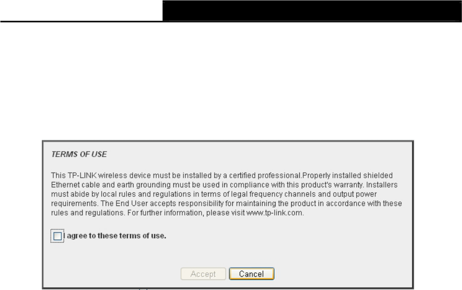
TL-WA7110ND 150Mbps High Power Wireless Access Point User Guide
Region- Select your region from the pull-down list. This field specifies the region where the
wireless function of the Device can be used. It may be illegal to use the wireless function
of the Device in a region other than one of those specified in this filed. If your country or
region
is not listed, please contact your local government agency for assistance.
When you select your local region from the pull-down list, the Note Dialog of TERMS OF USE
will pop up. Select I agree to these terms of use, and click Accept to continue.
Note:
Note Dialog
Ensure you select a correct country to comply with local laws. Incorrect settings may cause
interference. Limited to local law of the United States, selecting country code and channel
function was disabled.
Transmission Power - The available options of transmission power are determined by the
region selected.
Channel- This field determines which operating frequency will be used. It is not necessary to
change the wireless channel unless you notice interference problems with another nearby
access point. If you select auto, then the Device will select the best channel automatically.
Mode- This field determines the wireless mode which the Device works on.
Channel Width - The bandwidth of the wireless channel.
Enable Wireless Device Radio - The wireless radio of the Device can be
enabled or disabled to allow wireless stations access. If enabled, the wireless stations
will be able to access the Device, otherwise, wireless stations will not be able to access the
Device.
Enable SSID Broadcast - If you select the Enable SSID Broadcast checkbox, the wireless
Device will broadcast its name (SSID) on the air.
83
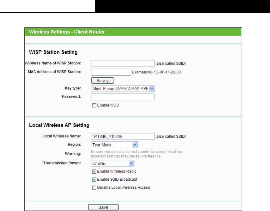
TL-WA7110ND 150Mbps High Power Wireless Access Point User Guide
2. Wireless settings in AP Client Router mode
Figure 5-17 Wireless Settings in AP Client Router mode
Wireless Name of WISP Station - The SSID of the AP your Device is going to connect to as
a client. You can also use the search function to select a SSID to join.
MAC Address of WISP Station - The BSSID of the AP your Device is going to connect to as
a client. You can also use the search function to select a BSSID to join.
Survey - Click this button, you can search the AP which runs in the current channel.
Key type - This option should be chosen according to the AP's security configuration. It is
recommended that the security type is the same as your AP's security type.
Auth Type - This option should be chosen if the key type is WEP (ASCII) or WEP (HEX). It
indicates the authorization type of the Root AP.
WEP Index - This option should be chosen if the key type is WEP (ASCII) or WEP (HEX). It
indicates the index of the WEP key.
Password - If the AP your Device is going to connect needs password, you need to fill the
password in this blank.
Local Wireless Name - Enter a value of up to 32 characters. The same Name (SSID) must
be assigned to all wireless devices in your network.
Region - Select your region from the pull-down list. This field specifies the region where the
wireless function of the Device can be used. It may be illegal to use the wireless function of
the Device in a region other than one of those specified in this filed. If your country or region
is not listed, please contact your local government agency for assistance.
When you select your local region from the pull-down list, the Note Dialog of TERMS OF USE
will pop up. Select I agree to these terms of use, and click Accept to continue.
84