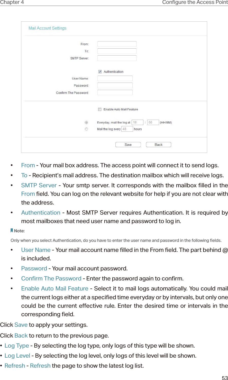
TP Link Technologies WA901NDV5 450Mbps Wireless N Access Point User Manual UG for FCC
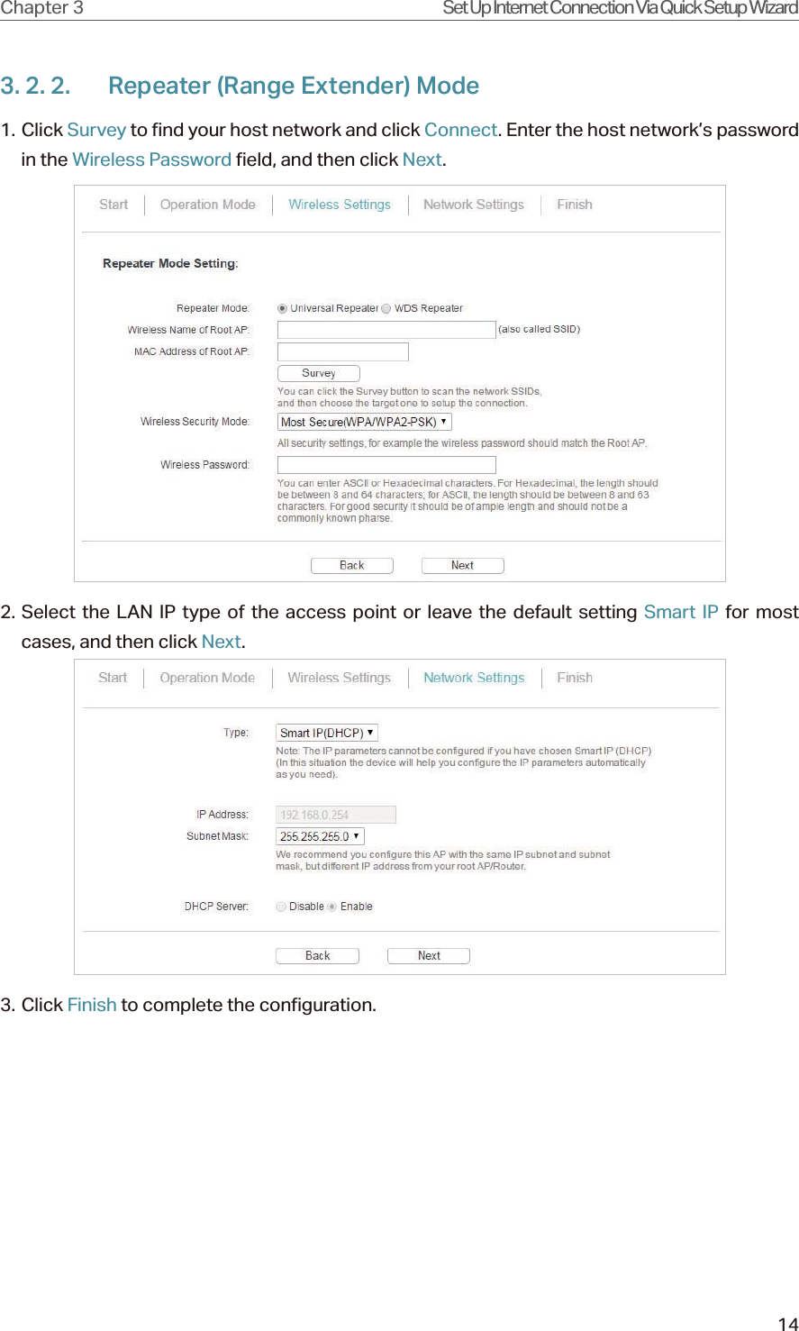
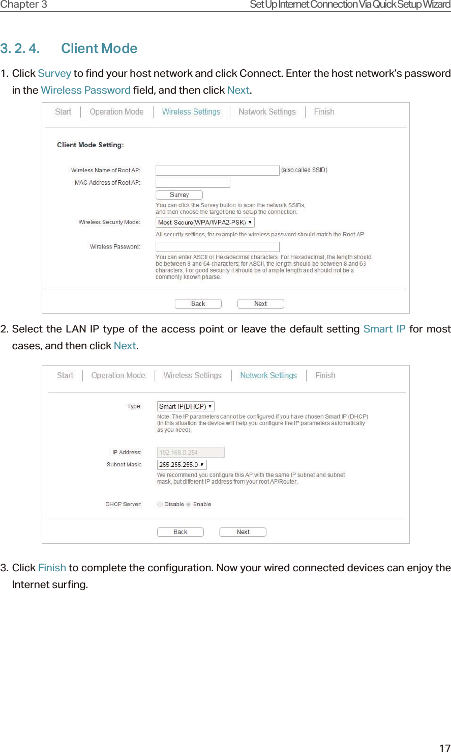
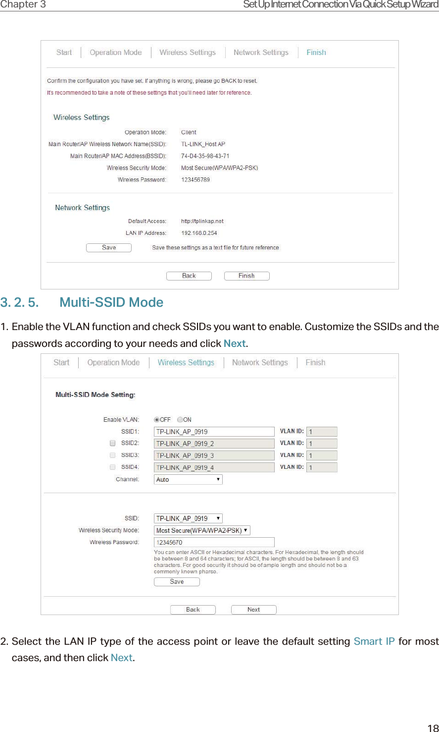
TP-Link Technologies Co., Ltd. 450Mbps Wireless N Access Point UG for FCC
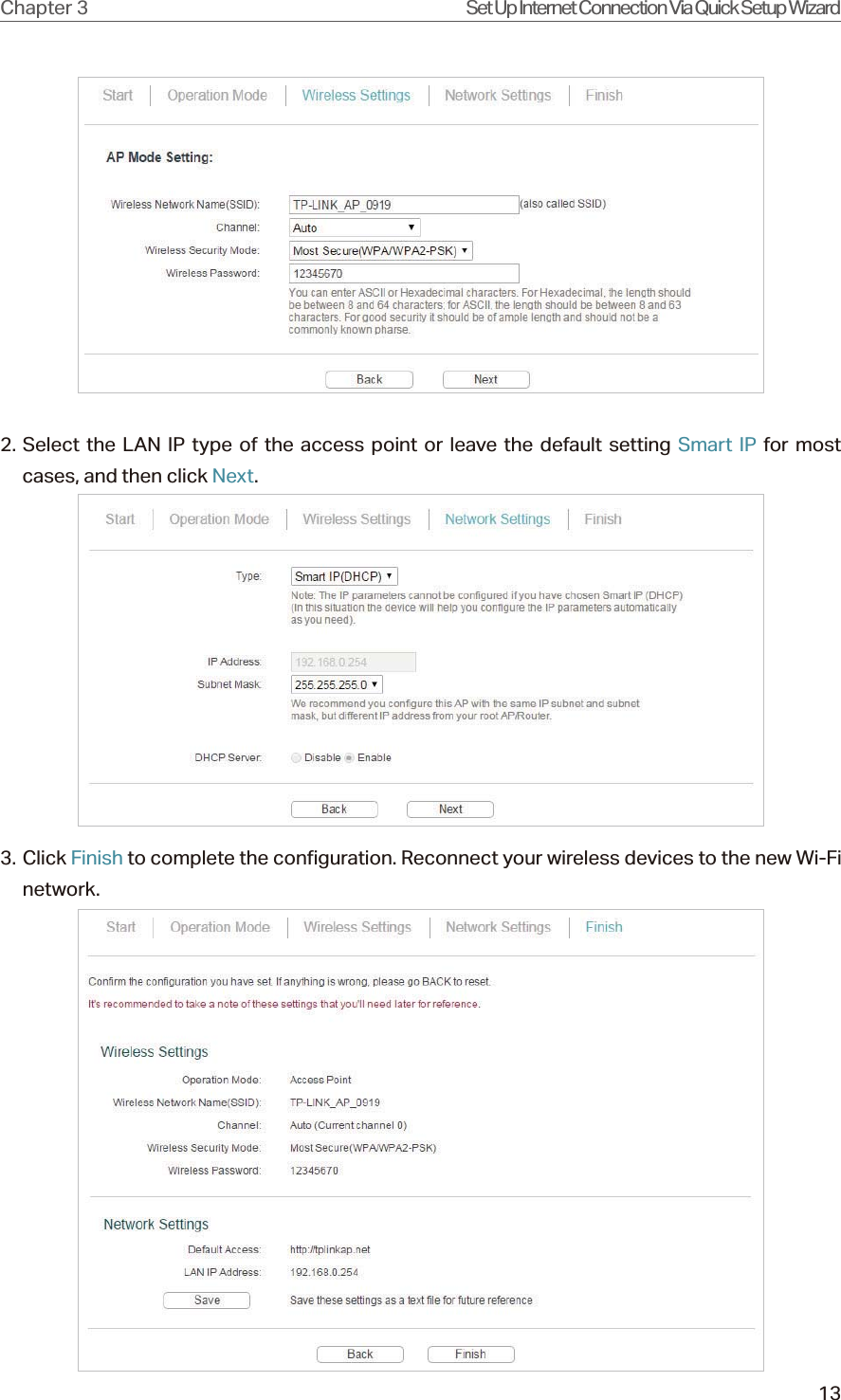
UserManual.wiki
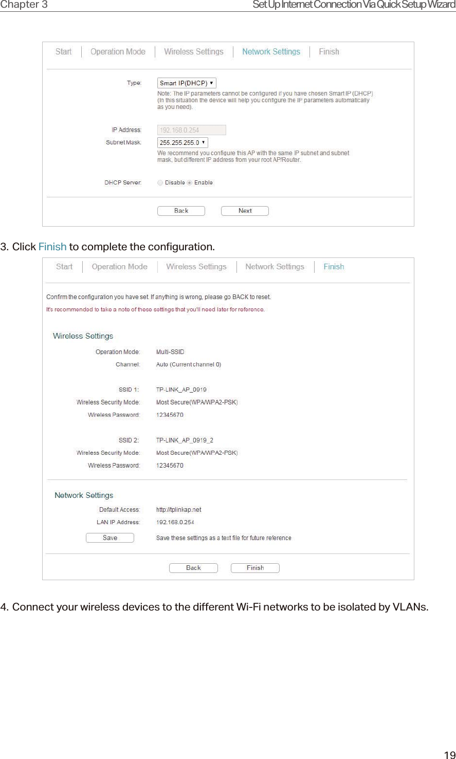
>
TP Link Technologies
>
WA901NDV5 User Manual
TL-WA901ND_UG
Navigation menu
Upload a User Manual
Namespaces
Wiki Guide
HTML
PDF
Info
Views
User Manual
Discussion / Help
Navigation

![Déclaration d'exposition aux radiations:Cet équipement est conforme aux limites d'exposition aux rayonnements IC établies pourun environnement non contrôlé. Cet équipement doit être installé et utilisé avec unminimum de 20 cm de distance entre la source de rayonnement et votre corps.Industry Canada StatementCAN ICES-3 (B)/NMB-3(B)Korea Warning Statements .NCC Notice !"#$!%&'()*+,-./01234 '56*34789:*;<= +,/0>?@ABCDEFGHIJKLEFKMN!OPQR,!STUVWEFNX0YZ+,<[\G]!^]_`abWc]< defG]*gb'hijDkl,8mEF<BSMI NoticeBCnoDp\q+,7rstOu*v;wxyz{|}s~+,yz{<yz{[qsc<q+,'*H<!q*yz{<tG+,!jyz{}a$S¡¢£!q¤¥*¦§<qyz{¨©ª«£s}¬X<"L®¯}G!°±/$©²³´µ¨¶<q/·¸2¹º!/·»¼2H½¾yz{!q¿ÀÁ}ÂbÃÄHÅ\ga<Продукт сертифіковано згідно с правилами системи УкрСЕПРО на відповідністьвимогам нормативних документів та вимогам, що передбачені чиннимизаконодавчими актами України.Safety Information](https://usermanual.wiki/TP-Link-Technologies/WA901NDV5/User-Guide-3285270-Page-63.png)