TP Link Technologies WA901NDV5 450Mbps Wireless N Access Point User Manual UG for FCC
TP-Link Technologies Co., Ltd. 450Mbps Wireless N Access Point UG for FCC
TL-WA901ND_UG

REV3.0.0 1910011930
User Guide
450Mbps/300Mbps Wireless N Access Point
TL-WA901ND/TL-WA801ND
Contents
Chapter 1. About This Guide . . . . . . . . . . . . . . . . . . . . . . . . . . . . . . . . . . . . . . . . .1
Chapter 2. Get to Know About Your Access Point . . . . . . . . . . . . . . . . . . . . .2
1. 1. Product Overview. . . . . . . . . . . . . . . . . . . . . . . . . . . . . . . . . . . . . . . . . . . . . . . . . . . . . . . . . . . . 3
1. 2. Panel Layout. . . . . . . . . . . . . . . . . . . . . . . . . . . . . . . . . . . . . . . . . . . . . . . . . . . . . . . . . . . . . . . . . 3
1. 2. 1. Top View . . . . . . . . . . . . . . . . . . . . . . . . . . . . . . . . . . . . . . . . . . . . . . . . . . . . . . . . . . . . . . 3
1. 2. 2. The Back Panel. . . . . . . . . . . . . . . . . . . . . . . . . . . . . . . . . . . . . . . . . . . . . . . . . . . . . . . . 4
Chapter 3. Connect the Hardware . . . . . . . . . . . . . . . . . . . . . . . . . . . . . . . . . . . .6
2. 1. Position Your Access Point. . . . . . . . . . . . . . . . . . . . . . . . . . . . . . . . . . . . . . . . . . . . . . . . . . . 7
2. 2. Connect Your Access Point . . . . . . . . . . . . . . . . . . . . . . . . . . . . . . . . . . . . . . . . . . . . . . . . . . 7
2. 2. 1. Access Point Mode. . . . . . . . . . . . . . . . . . . . . . . . . . . . . . . . . . . . . . . . . . . . . . . . . . . . 7
2. 2. 2. Repeater (Range Extender) Mode. . . . . . . . . . . . . . . . . . . . . . . . . . . . . . . . . . . . . . 8
2. 2. 3. Bridge with AP Mode . . . . . . . . . . . . . . . . . . . . . . . . . . . . . . . . . . . . . . . . . . . . . . . . . . 8
2. 2. 4. Client Mode . . . . . . . . . . . . . . . . . . . . . . . . . . . . . . . . . . . . . . . . . . . . . . . . . . . . . . . . . . . 9
2. 2. 5. Multi-SSID Mode . . . . . . . . . . . . . . . . . . . . . . . . . . . . . . . . . . . . . . . . . . . . . . . . . . . . . . 9
Chapter 4. Set Up Internet Connection Via Quick Setup Wizard. . . . . 11
3. 1. Log in to the Access Point . . . . . . . . . . . . . . . . . . . . . . . . . . . . . . . . . . . . . . . . . . . . . . . . . . 12
3. 2. Configure the Access Point . . . . . . . . . . . . . . . . . . . . . . . . . . . . . . . . . . . . . . . . . . . . . . . . . 12
3. 2. 1. Access Point Mode . . . . . . . . . . . . . . . . . . . . . . . . . . . . . . . . . . . . . . . . . . . . . . . . . .12
3. 2. 2. Repeater (Range Extender) Mode. . . . . . . . . . . . . . . . . . . . . . . . . . . . . . . . . . . . . 14
3. 2. 3. Bridge with AP Mode . . . . . . . . . . . . . . . . . . . . . . . . . . . . . . . . . . . . . . . . . . . . . . . . . 15
3. 2. 4. Client Mode . . . . . . . . . . . . . . . . . . . . . . . . . . . . . . . . . . . . . . . . . . . . . . . . . . . . . . . . . . 17
3. 2. 5. Multi-SSID Mode . . . . . . . . . . . . . . . . . . . . . . . . . . . . . . . . . . . . . . . . . . . . . . . . . . . . . 18
Chapter 5. Configure the Access Point . . . . . . . . . . . . . . . . . . . . . . . . . . . . . 20
4. 1. Status . . . . . . . . . . . . . . . . . . . . . . . . . . . . . . . . . . . . . . . . . . . . . . . . . . . . . . . . . . . . . . . . . . . . . . 21
4. 2. WPS. . . . . . . . . . . . . . . . . . . . . . . . . . . . . . . . . . . . . . . . . . . . . . . . . . . . . . . . . . . . . . . . . . . . . . . . 22
4. 3. Network . . . . . . . . . . . . . . . . . . . . . . . . . . . . . . . . . . . . . . . . . . . . . . . . . . . . . . . . . . . . . . . . . . . . 24
4. 3. 1. LAN. . . . . . . . . . . . . . . . . . . . . . . . . . . . . . . . . . . . . . . . . . . . . . . . . . . . . . . . . . . . . . . . 24
4. 3. 2. DHCP Settings . . . . . . . . . . . . . . . . . . . . . . . . . . . . . . . . . . . . . . . . . . . . . . . . . . . . . . . 24
4. 3. 3. DHCP Client List . . . . . . . . . . . . . . . . . . . . . . . . . . . . . . . . . . . . . . . . . . . . . . . . . . . . . 26
4. 4. Wireless . . . . . . . . . . . . . . . . . . . . . . . . . . . . . . . . . . . . . . . . . . . . . . . . . . . . . . . . . . . . . . . . . . . . 26
4. 4. 1. Wireless Settings . . . . . . . . . . . . . . . . . . . . . . . . . . . . . . . . . . . . . . . . . . . . . . . . . . . . 26
4. 4. 2. Wireless Security . . . . . . . . . . . . . . . . . . . . . . . . . . . . . . . . . . . . . . . . . . . . . . . . . . . . 32
4. 4. 3. Wireless MAC Filtering . . . . . . . . . . . . . . . . . . . . . . . . . . . . . . . . . . . . . . . . . . . . . . . 42
4. 4. 4. Wireless Advanced. . . . . . . . . . . . . . . . . . . . . . . . . . . . . . . . . . . . . . . . . . . . . . . . . . . 44
4. 4. 5. Wireless Statistics . . . . . . . . . . . . . . . . . . . . . . . . . . . . . . . . . . . . . . . . . . . . . . . . . . . 45
4. 4. 6. Throughput Monitor . . . . . . . . . . . . . . . . . . . . . . . . . . . . . . . . . . . . . . . . . . . . . . . . . . 45
4. 5. System Tools . . . . . . . . . . . . . . . . . . . . . . . . . . . . . . . . . . . . . . . . . . . . . . . . . . . . . . . . . . . . . . . 46
4. 5. 1. SNMP. . . . . . . . . . . . . . . . . . . . . . . . . . . . . . . . . . . . . . . . . . . . . . . . . . . . . . . . . . . . . . . . 46
4. 5. 2. Diagnostic . . . . . . . . . . . . . . . . . . . . . . . . . . . . . . . . . . . . . . . . . . . . . . . . . . . . . . . . . . . 47
4. 5. 3. Ping Watch Dog . . . . . . . . . . . . . . . . . . . . . . . . . . . . . . . . . . . . . . . . . . . . . . . . . . . . . . 49
4. 5. 4. Firmware Upgrade. . . . . . . . . . . . . . . . . . . . . . . . . . . . . . . . . . . . . . . . . . . . . . . . . . . .50
4. 5. 5. Factory Defaults . . . . . . . . . . . . . . . . . . . . . . . . . . . . . . . . . . . . . . . . . . . . . . . . . . . . . 50
4. 5. 6. Backup & Restore . . . . . . . . . . . . . . . . . . . . . . . . . . . . . . . . . . . . . . . . . . . . . . . . . . . . 50
4. 5. 7. Reboot . . . . . . . . . . . . . . . . . . . . . . . . . . . . . . . . . . . . . . . . . . . . . . . . . . . . . . . . . . . . . . . 51
4. 5. 8. Password . . . . . . . . . . . . . . . . . . . . . . . . . . . . . . . . . . . . . . . . . . . . . . . . . . . . . . . . . . . . 51
4. 5. 9. System Log . . . . . . . . . . . . . . . . . . . . . . . . . . . . . . . . . . . . . . . . . . . . . . . . . . . . . . . . . . 52
4. 6. Logout . . . . . . . . . . . . . . . . . . . . . . . . . . . . . . . . . . . . . . . . . . . . . . . . . . . . . . . . . . . . . . . . . . . . . 54
Chapter 6. FAQ. . . . . . . . . . . . . . . . . . . . . . . . . . . . . . . . . . . . . . . . . . . . . . . . . . . . . 55

1
About This Guide
This guide is a complement to Quick Installation Guide. The Quick Installation Guide
provides instructions for quick Internet setup, while this guide contains details of each
function and demonstrates how to configure them.
When using this guide, please notice that features of the access point may vary slightly
depending on the model and software version you have, and on your location, language,
and Internet service provider. All screenshots, images, parameters and descriptions
documented in this guide are used for demonstration only.
Conventions
In this guide the following conventions are used:
Convention Description
Underlined Underlined words or phrases are hyperlinks. You can click to redirect to a website or a
specific section.
Teal Contents to be emphasized and texts on the web page are in teal, including the menus,
items, buttons and so on.
>
The menu structures to show the path to load the corresponding page. For example,
Advanced > Wireless > MAC Filtering means the MAC Filtering function page is under the
Wireless menu that is located in the Advanced tab.
Note: Ignoring this type of note might result in a malfunction or damage to the device.
Tips: Indicates important information that helps you make better use of your device.
More Info
The latest software, management app and utility are available from the Download
Center at www.tp-link.com/support.
The Quick Installation Guide can be found where you find this guide or inside the
package of the access point.
Specifications can be found on the product page at http://www.tp-link.com.
A Technical Support Forum is provided for you to discuss our products at
http://forum.tp-link.com.
Our Technical Support contact information can be found at the Contact Technical
Support page at www.tp-link.com/support.

Chapter 1
Get to Know About Your
Access Point
This chapter introduces what the access point can do and shows its appearance.
It contains the following sections:
• Product Overview
• Panel Layout
3
Chapter 1 Get to Know About Your Access Point
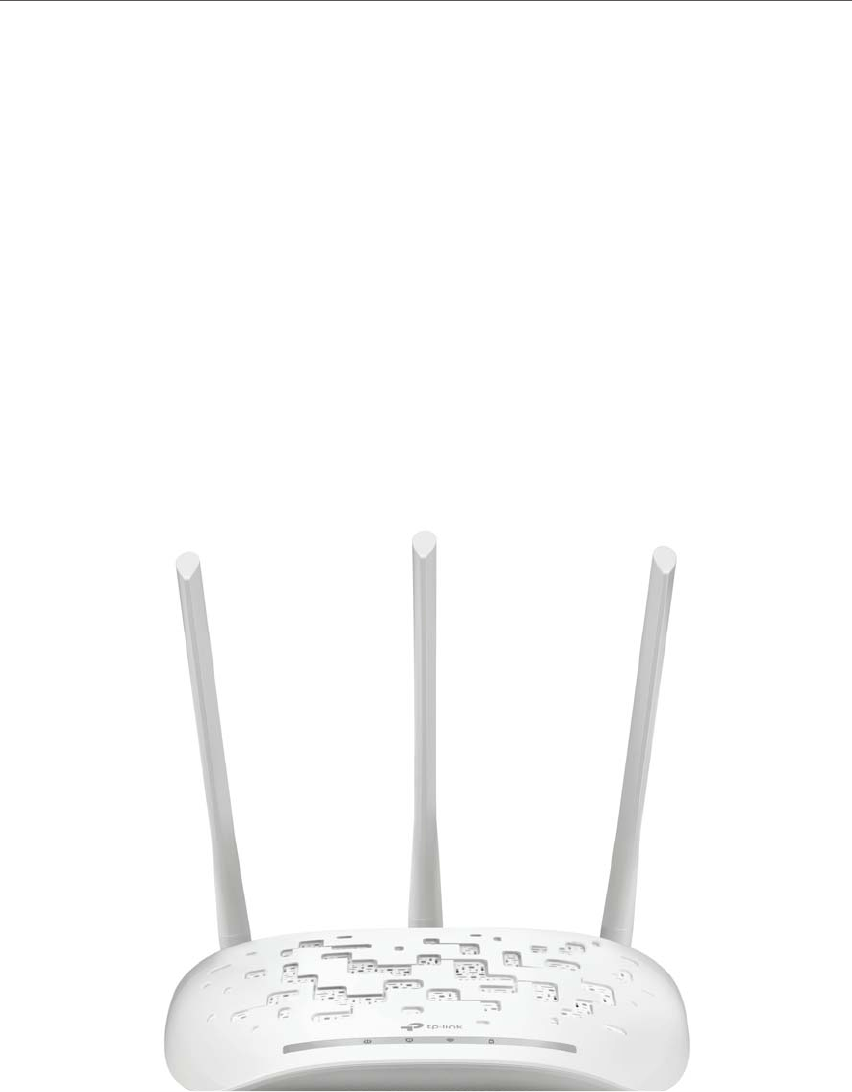
1. 1. Product Overview
The TP-LINK Wireless N Access Point, with multiple operation modes, is designed to
establish or expand a scalable high-speed wireless N network or to connect multiple
Ethernet enabled devices such as game consoles, digital media adapters, printers, or
network attached storage devices to a wireless network. The AP supports a host of
dierent functions that makes your wireless networking experience more exible than ever
before. Now, you can enjoy a better Internet experience when downloading, gaming,
video streaming or with any other application that you may wish to use.
1. 2. Panel Layout
1. 2. 1. Top View
The access point’s LEDs (view from left to right) are located on the front panel. You can
check the access point’s working status by following the LED Explanation table.
4
Chapter 1 Get to Know About Your Access Point
LED Explanation
Name Status Indication
(Power)
On The device is on.
Flashing The device is initializing or upgrading.
Off The device is off.
(Wireless)
On The wireless function is working properly.
Off The wireless function is disabled.
(Ethernet)
On A device is connected to the Ethernet port.
Off No device is connected to the Ethernet port.
(WPS)
On A wireless device has been successfully added to the network by WPS
function.
Off The WPS function is disabled or a wireless device failed to be added to
the network in 2 minutes after WPS function is enabled.
Flashing A wireless device is connecting to the network by WPS function. This
process will last in first 2 minutes.
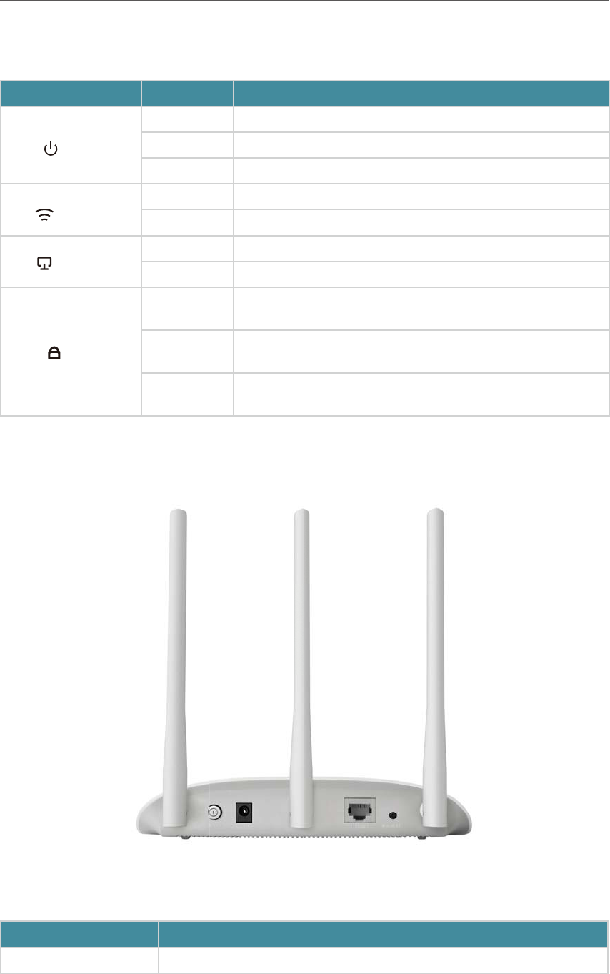
1. 2. 2. The Back Panel
The following parts (view from left to right) are located on the rear panel.
Item Description
ON/OFF The switch for the power.

5
Chapter 1 Get to Know About Your Access Point
Item Description
Power For connecting the access point to a power socket via the provided power adapter.
Ethernet One LAN 10/100Mbps RJ45 port connects to a network device, such as a switch or
a router.
WPS/RESET
Press and hold this button until SYS LED becomes quick-flash from slow-flash to
reset the access point to its factory default settings.
If you have client devices, such as wireless adapters, that support Wi-Fi Protected
Setup, then you can press this button to quickly establish a connection between the
Access Point and client devices and automatically configure wireless security for
your wireless network.
Antennas Used for wireless operation and data transmitting. Upright them for the best Wi-Fi
performance.

Chapter 2
Connect the Hardware
This chapter contains the following sections:
• Position Your Access Point
• Connect Your Access Point

7
Chapter 2 $POOFDUUIF)BSEXBSF
2. 1. Position Your Access Point
• The product should not be located where it will be exposed to moisture or excessive
heat.
• Place the access point in a location where it can be connected to various devices as
well as to a power source.
• Make sure the cables and power cord are safely placed out of the way so they do not
create a tripping hazard.
• The access point can be placed on a shelf or desktop.
• Please keep away from the strong electromagnetic radiation and the device of
electromagnetic sensitive.
2. 2. Connect Your Access Point
There are five operation modes supported by this access point: Access Point, Repeater,
Bridge with AP, Client and Multi-SSID. Please determine which operation mode you
need and carry out the corresponding steps.
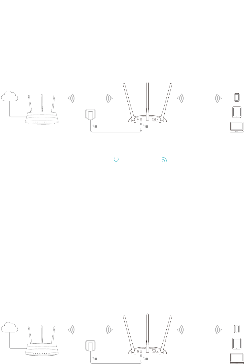
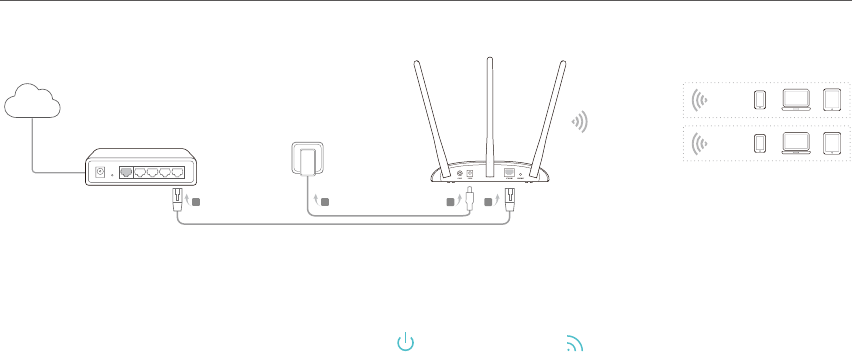
2. 2. 1. Access Point Mode
Transforms your existing wired network to a wireless one. This mode is suitable for dorm
rooms or homes where there’s already a wired router but you need a wireless hotspot.
Wired Router
Internet
TL-WA901ND’s SSID
A
B
C
D
1. Connect the AP device according to steps A to D in the diagram.
2. Turn on the power, wait until the Power ( ) and Wireless ( ) LEDs are lit and stable, and
use the default SSID and Password printed on the product label to join the AP device’s Wi-Fi
network.
Note:
You can enjoy the Internet surfing now. For your wireless network security, it is recommended to change the default
SSID (network name) and the password of your Wi-Fi network. To do so, perform the following steps.
3. Launch a web browser and enter http://tplinkap.net. Then log in using admin (all lowercase) for
both Username and Password.
4. Click Quick Setup, select Access Point mode and click Next. Follow the step-by-step
instructions to complete the configuration.
8
Chapter 2 $POOFDUUIF)BSEXBSF
5. Now, reconnect your wireless devices to the new Wi-Fi network.
2. 2. 2. Repeater (Range Extender) Mode
Extends the range of an existing Wi-Fi network. This mode is suitable if you are in a Wi-Fi
dead-zone or a place with weak wireless signal, and you want to have a greater effective
range of the wireless signal throughout your home or office.
Internet Host AP’s SSID Host AP’s SSID
A
B
1. Connect the AP device according to steps A and B in the diagram.
2. Turn on the power, wait until the Power ( ) and Wireless ( ) LEDs are lit and stable, and
use the default SSID and Password printed on the product label to join the AP device’s Wi-Fi
network.
3. Launch a web browser and enter http://tplinkap.net. Then log in using admin (all lowercase) for
both Username and Password.
4. Click Quick Setup, select Repeater (Range Extender) mode and click Next. Follow the step-
by-step instructions to complete the configuration.
5. Relocate the AP device to a good place.
6. Now, connect your wireless devices to the Wi-Fi network using the Host AP ’s SSID and
password.
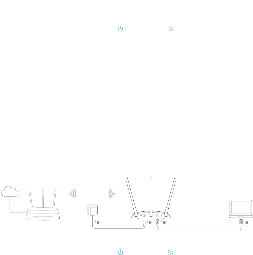
2. 2. 3. Bridge with AP Mode
Combines two local networks via wireless connection. This mode is suitable if you want
to link multiple local networks to the same network using wireless connections where
physical wires are inconvenient (when connecting networks in different office buildings,
for example).
Internet
TL-WA901ND’s SSID
Host AP’s SSID
ON/OFF POWER ETHERNET WPS/RESET
A
B
9
Chapter 2 $POOFDUUIF)BSEXBSF
1. Connect the AP device according to steps A and B in the diagram.
2. Turn on the power, wait until the Power ( ) and Wireless ( ) LEDs are lit and stable, and
use the default SSID and Password printed on the product label to join the AP device’s Wi-Fi
network.
3. Launch a web browser and enter http://tplinkap.net. Then log in using admin (all lowercase) for
both Username and Password.
4. Click Quick Setup, select Bridge with AP mode and click Next. Follow the step-by-step
instructions to complete the configuration.
5. Relocate the AP device to a good place.
6. Now, connect your wireless devices to the Wi-Fi network using the AP device’s SSID and
password.
2. 2. 4. Client Mode
Connects your wired devices to a wireless network.This mode is suitable if you have a
wired device with an Ethernet port and no wireless capability, for example, a Smart TV,
Media Player, or game console and you want to connect it to the Internet wirelessly.
Internet Host AP’s SSID
A
B
D
C
1. Connect the AP device according to steps A to D in the diagram.
2. Turn on the power, wait until the Power ( ) and Wireless ( ) LEDs are lit and stable, and
use the default SSID and Password printed on the product label to join the AP device’s Wi-Fi
network.
3. Launch a web browser and enter http://tplinkap.net. Then log in using admin (all lowercase) for
both Username and Password.
4. Click Quick Setup, select Client mode and click Next. Follow the step-by-step instructions to
complete the configuration.
5. Now, your wired connected devices can enjoy the Internet surfing.
2. 2. 5. Multi-SSID Mode
Creates multiple wireless networks to provide different security and VLAN groups. This
mode is suitable if you want your devices connected to different wireless networks and
isolated by VLANs.
10
Chapter 2 $POOFDUUIF)BSEXBSF
TL-WA901ND’s SSID
VLAN 2
VLAN 1
Wired Router
Internet
AC
B D
1. Connect the AP device according to steps A to D in the diagram.
2. Turn on the power, wait until the Power ( ) and Wireless ( ) LEDs are lit and stable, and
use the default SSID and Password printed on the product label to join the AP device’s Wi-Fi
network.
3. Launch a web browser and enter http://tplinkap.net. Then log in using admin (all lowercase) for
both Username and Password.
4. Click Quick Setup, then select Multi-SSID mode and click Next. Follow the step-by-step
instructions to complete the configuration.
5. Now, connect your wireless devices to the different Wi-Fi networks to be isolated by VLANs.

Chapter 3
Set Up Internet Connection
Via Quick Setup Wizard
This chapter introduces how to connect your access point to the Internet via the web-
based Quick Setup Wizard.
It contains the following sections:
• Log in to the Access Point
• Configure the Access Point
12
Chapter 3 Set Up Internet Connection Via Quick Setup Wizard
3. 1. Log in to the Access Point
With a Web-based utility, it is easy to configure and manage the access point. The Web-
based utility can be used on any Windows, Macintosh or UNIX OS with a Web browser,
such as Microsoft Internet Explorer, Mozilla Firefox or Apple Safari.
Follow the steps below to log into your access point.
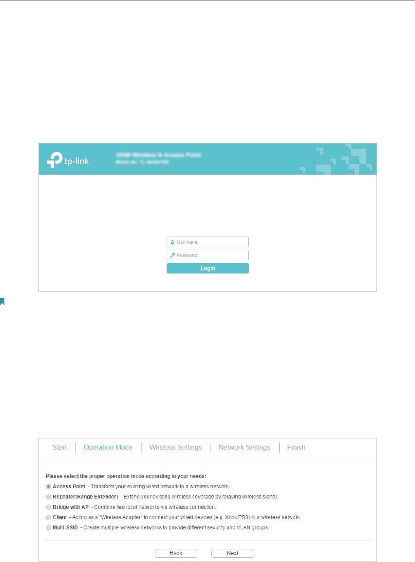
1. Visit http://tplinkap.net, and log in using admin (all lowercase) for both Username and Password.
Note:
If the login window does not appear, please refer to FAQ Section.
3. 2. Configure the Access Point
The Quick Setup Wizard will guide you through the process to set up your access point.
1. Go to Quick Setup and click Next to start.
2. Choose the working mode you need and click Next. Then follow the corresponding steps to
configure your access point to the Internet.
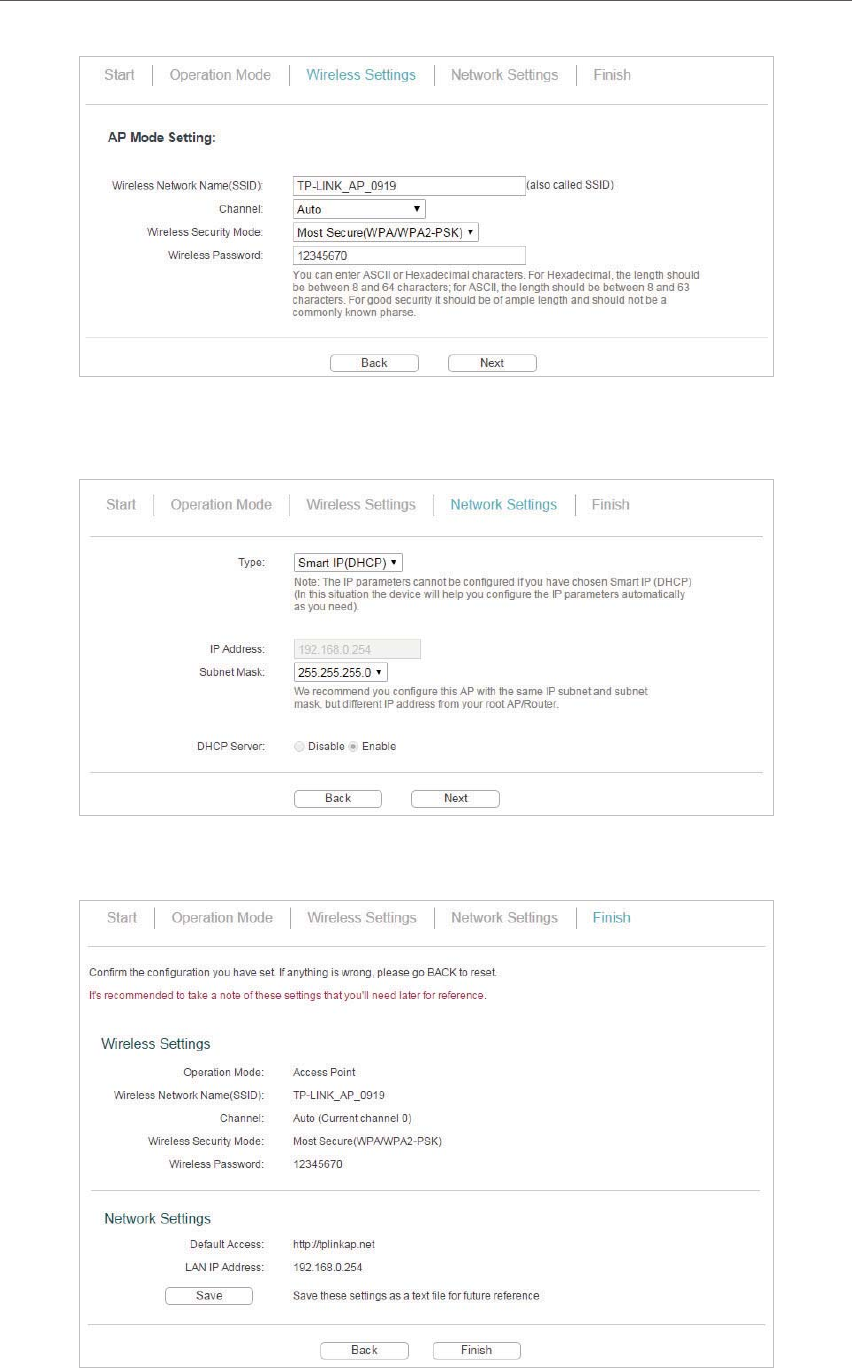
3. 2. 1. Access Point Mode
1. Either customize your Wireless Network Name and Wireless Password or keep the default
ones, and then click Next.
13
Chapter 3 Set Up Internet Connection Via Quick Setup Wizard
2. Select the LAN IP type of the access point or leave the default setting Smart IP for most
cases, and then click Next.
3. Click Finish to complete the configuration. Reconnect your wireless devices to the new Wi-Fi
network.
14
Chapter 3 Set Up Internet Connection Via Quick Setup Wizard
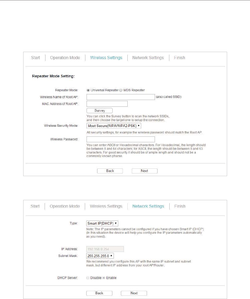
3. 2. 2. Repeater (Range Extender) Mode
1. Click Survey to find your host network and click Connect. Enter the host network’s password
in the Wireless Password field, and then click Next.
2. Select the LAN IP type of the access point or leave the default setting Smart IP for most
cases, and then click Next.
3. Click Finish to complete the configuration.
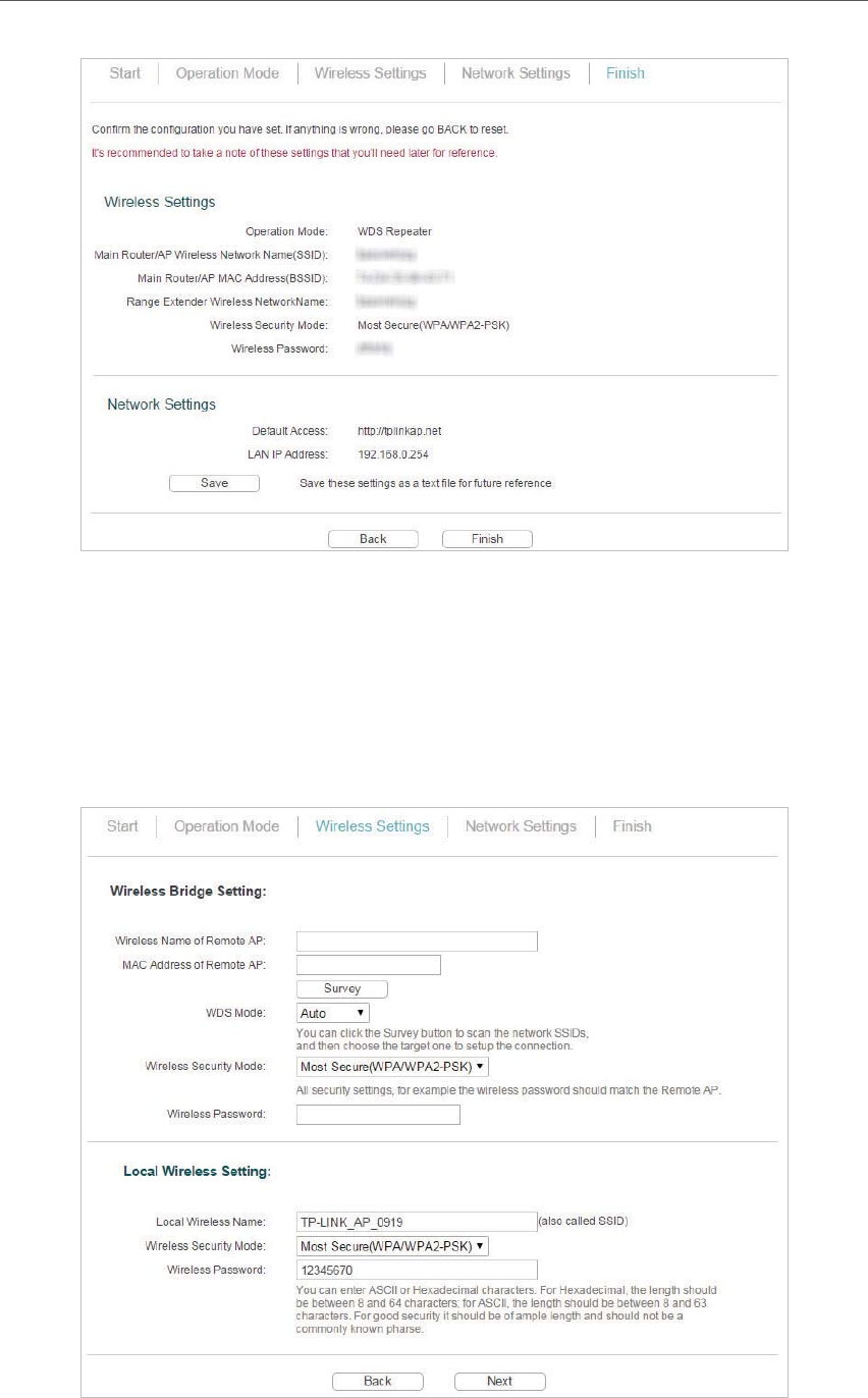
15
Chapter 3 Set Up Internet Connection Via Quick Setup Wizard
4. Relocate the access point about halfway between your host AP and the Wi-Fi dead zone. The
extended network shares the same network name and password as your host network.
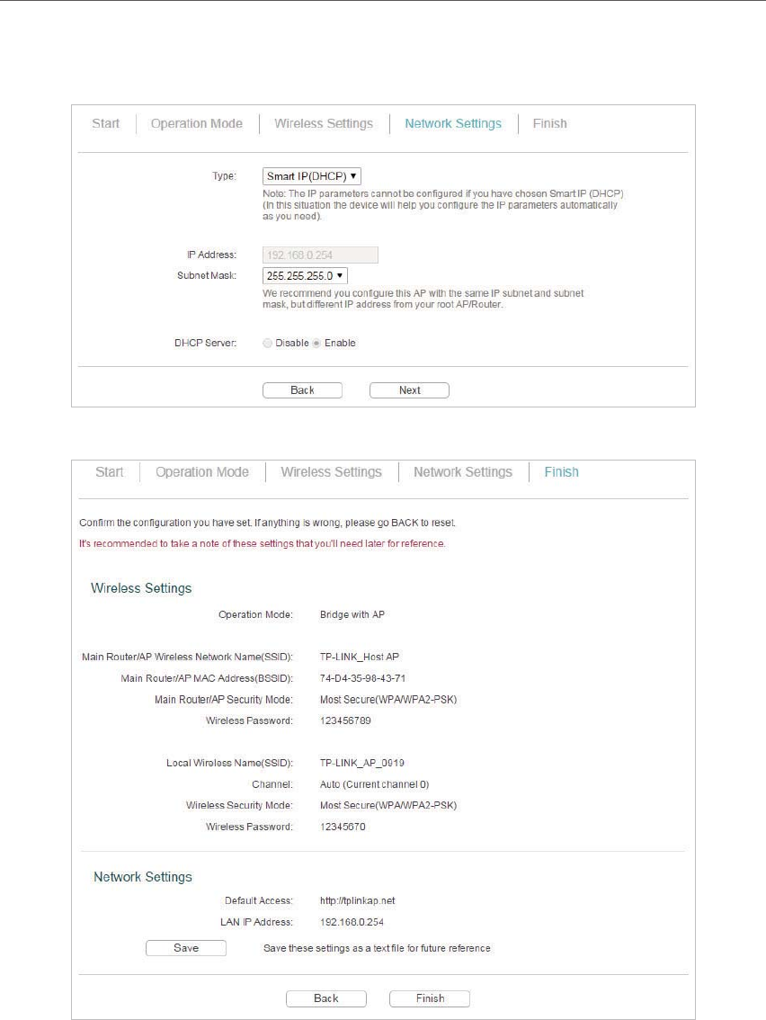
3. 2. 3. Bridge with AP Mode
1. Click Survey to find your host network, enter the host network’s password in the Wireless
Password field. In the Local Wireless Setting section, either customize your Local Wireless
Name and Wireless Password or keep the default ones, and then click Next.
16
Chapter 3 Set Up Internet Connection Via Quick Setup Wizard
2. Select the LAN IP type of the access point or leave the default setting Smart IP for most
cases, and then click Next.
3. Click Finish to complete the configuration.
4. Relocate the access point to a good place. Connect your wireless devices to the Wi-Fi network
using the AP’s SSID and password.
17
Chapter 3 Set Up Internet Connection Via Quick Setup Wizard
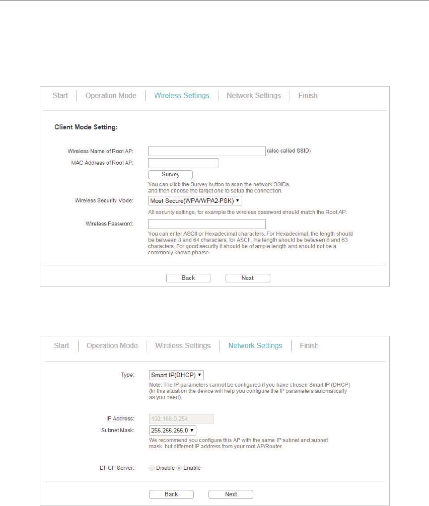
3. 2. 4. Client Mode
1. Click Survey to find your host network and click Connect. Enter the host network’s password
in the Wireless Password field, and then click Next.
2. Select the LAN IP type of the access point or leave the default setting Smart IP for most
cases, and then click Next.
3. Click Finish to complete the configuration. Now your wired connected devices can enjoy the
Internet surfing.
18
Chapter 3 Set Up Internet Connection Via Quick Setup Wizard
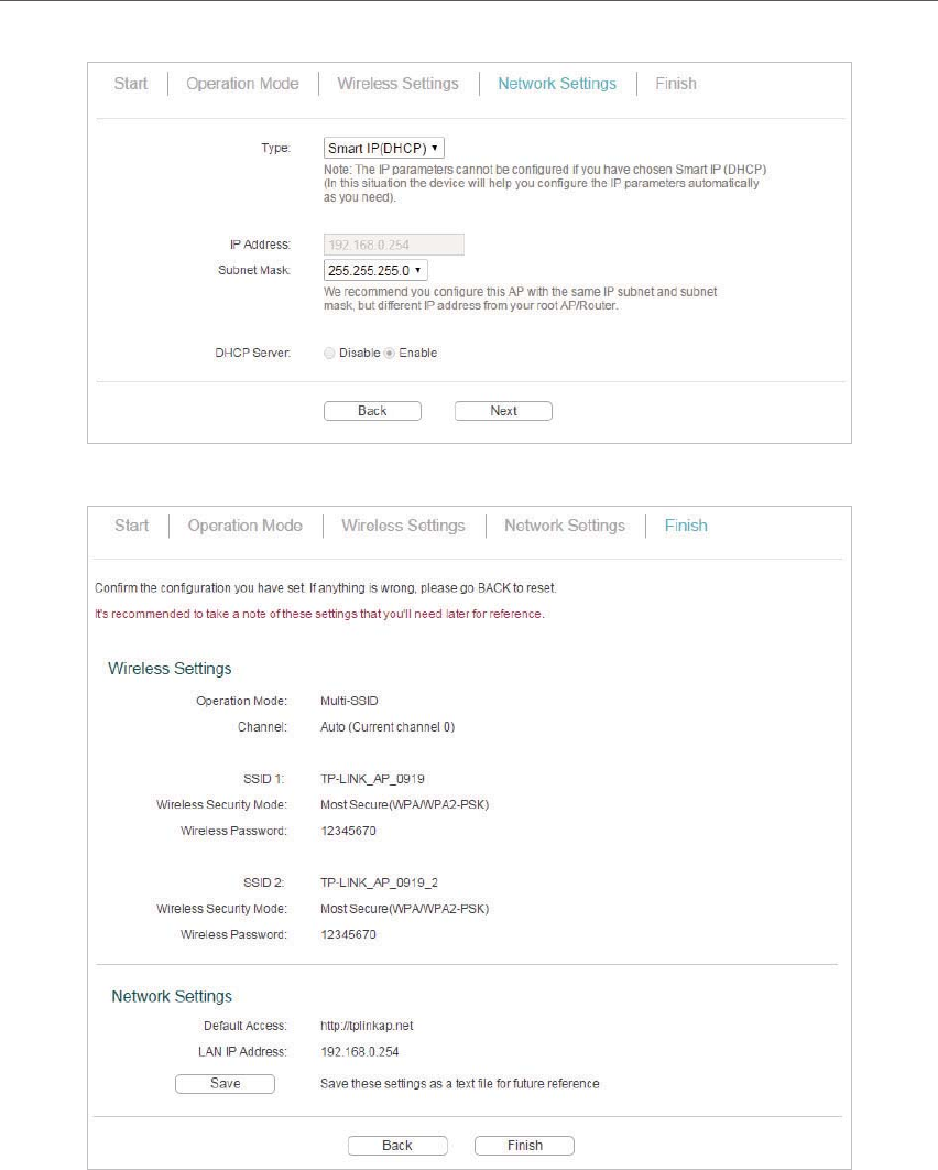
3. 2. 5. Multi-SSID Mode
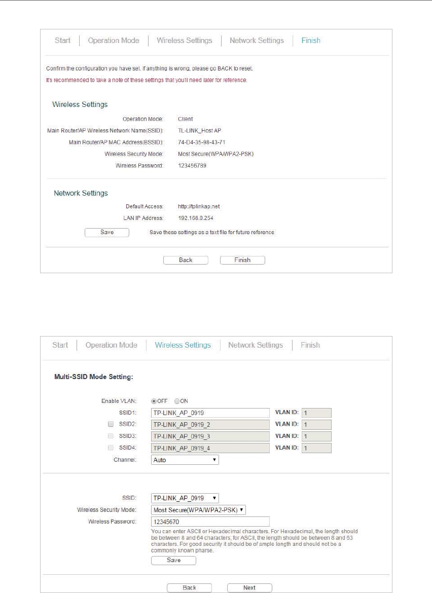
1. Enable the VLAN function and check SSIDs you want to enable. Customize the SSIDs and the
passwords according to your needs and click Next.
2. Select the LAN IP type of the access point or leave the default setting Smart IP for most
cases, and then click Next.
19
Chapter 3 Set Up Internet Connection Via Quick Setup Wizard
3. Click Finish to complete the configuration.
4. Connect your wireless devices to the different Wi-Fi networks to be isolated by VLANs.

Chapter 4
This chapter presents how to configure the various features of your Access Point.
This chapter contains the following sections:
• Status
• WPS
• Network
• Wireless
• System Tools
• Logout
21
Chapter 4
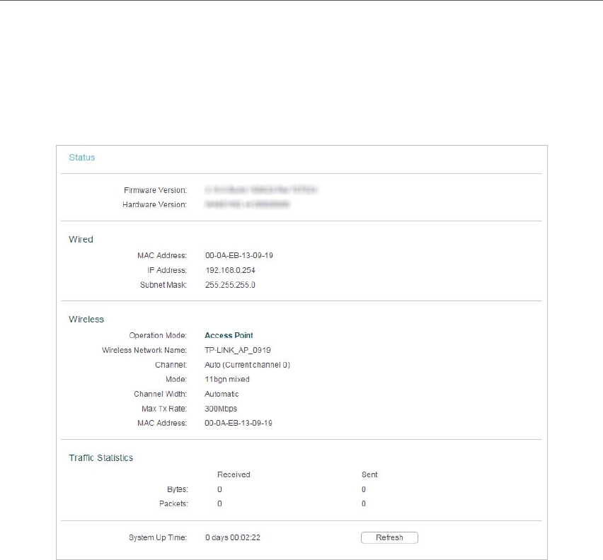
4. 1. Status
1. Visit http://tplinkap.net, and log in using admin (all lowercase) for both Username and Password.
2. Go to Status. You can view the current status information of the access point.
• Firmware Version - The version information of the access point’s firmware.
• Hardware Version - The version information of the access point’s hardware.
• Wired - This field displays the current settings of the LAN, and you can configure them
on the Network > LAN page.
• MAC address - The physical address of the access point.
• IP address - The LAN IP address of the access point.
• Subnet Mask - The subnet mask associated with the LAN IP address.
• Wireless - This field displays the basic information or status of the wireless function,
and you can configure them on the Wireless > Wireless Settings page.
• Operation Mode - The current wireless working mode in use.
• Wireless Network Name - The SSID of the access point.
• Channel - The current wireless channel in use.
• Mode - The current wireless mode which the access point works on.
• Channel Width - The current wireless channel width in use.
• Max Tx Rate - The highset tranmit rate of the access point.
22
Chapter 4
• MAC Address - The physical address of the access point.
• Traffic Statistics - The access point’s traffic stastics.
• Received (Bytes) - Traffic in bytes received from the ETHERNET port.
• Received (Packets) - Traffic in packets received from the ETHERNET port.
• Sent (Bytes) - Traffic in bytes sent out from the ETHERNET port.
• Sent (Packets) - Traffic in packets sent out from the ETHERNET port.
• System Up Time - The length of the time since the access point was last
powered on or reset.
Click Refresh to get the latest status and settings of the access point.
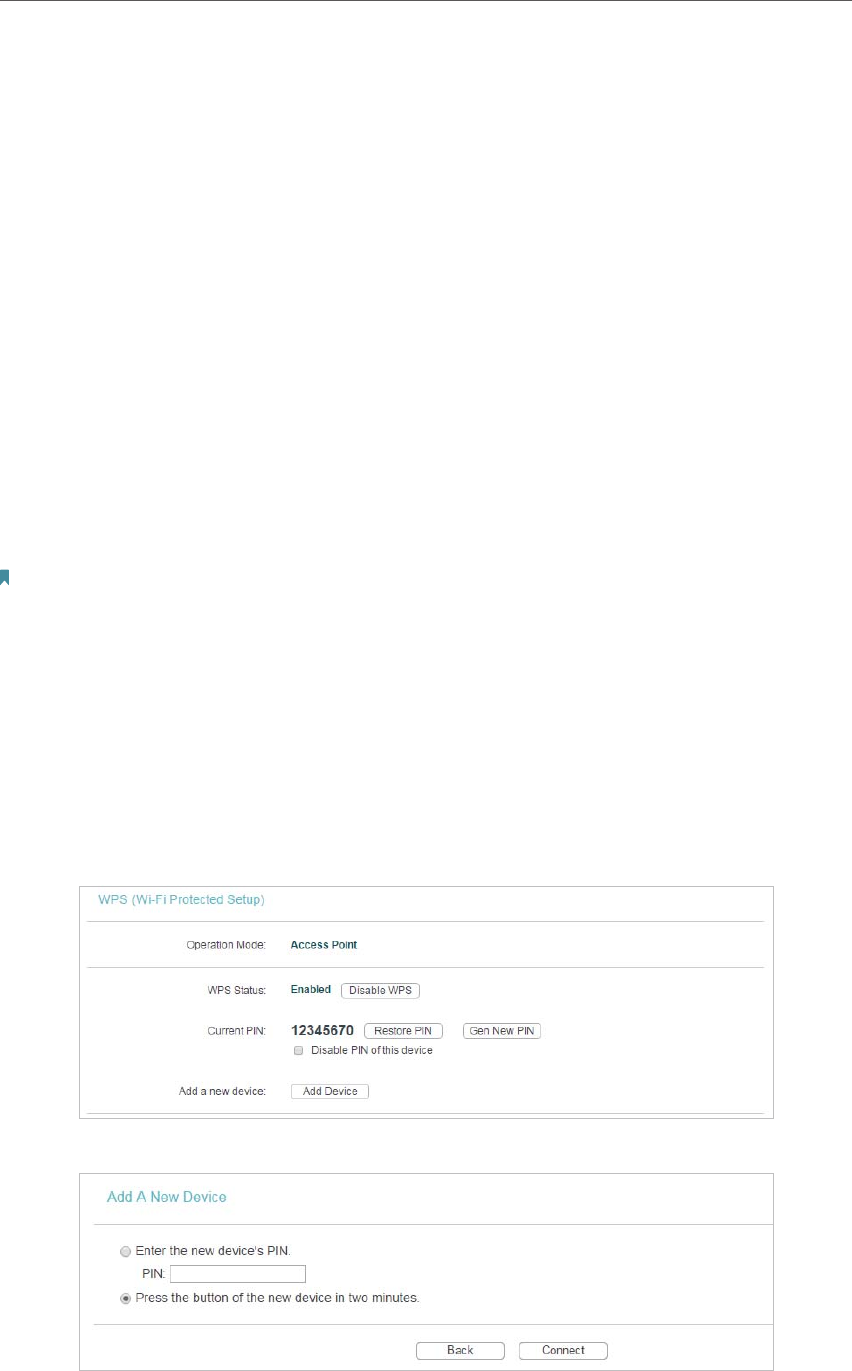
4. 2. WPS
WPS (Wi-Fi Protected Setup) can help you to quickly and securely connect to a network.
This section will guide you to add a new wireless device to your access point’s network
quickly via WPS.
Note:
The WPS function cannot be configured if the wireless function of the access point is disabled. Please make sure the
wireless function is enabled before configuration.
1. Visit http://tplinkap.net, and log in using admin (all lowercase) for both Username and Password.
2. Go to WPS.
3. Follow one of the following three methods to connect your client device to the access point’s
Wi-Fi network.
Method ONE: Press the WPS Button on Your Client Device
1. Keep the WPS Status as Enabled and click Add Device.
2. Select Press the button of the new device in two minutes and click Connect.
23
Chapter 4
3. Within two minutes, press the WPS button on your client device.
4. A success message will appear on the WPS page if the client device has been successfully
added to the access point’s network.
Method TWO: Enter the Client’s PIN
1. Keep the WPS Status as Enabled and click Add Device.
2. Select Enter the new device’s PIN, enter your client device’s current PIN in the PIN filed and
click Connect.
3. A success message will appear on the WPS page if the client device has been successfully
added to the access point’s network.
Method Three: Enter the Access Point’s PIN
1. Keep the WPS Status as Enabled and get the Current PIN of the access point.
2. Enter the access point’s current PIN on your client device to join the access point’s Wi-Fi
network.
24
Chapter 4
4. 3. Network
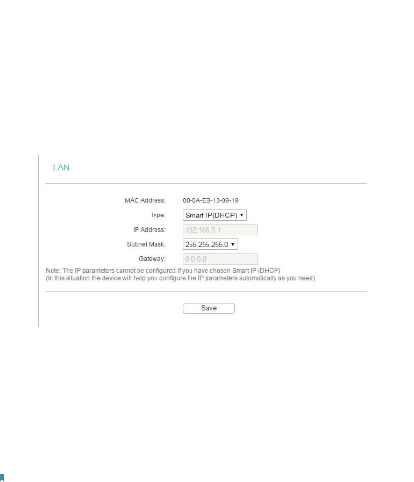
4. 3. 1. LAN
1. Visit http://tplinkap.net, and log in using admin (all lowercase) for both Username and Password.
2. Go to Network > LAN.
3. Configure the IP parameters of the LAN and click Save.
• MAC Address - The physical address of the LAN ports. The value can not be changed.
• Type - Either select Smart IP(DHCP) to get IP address from DHCP server, or Static IP
to configure IP address manually.
• IP Address - Enter the IP address in dotted-decimal notation if your select Static IP
(factory default - 192.168.0.254).
• Subnet Mask - An address code that determines the size of the network. Normally
255.255.255.0 is used as the subnet mask.
• Gateway - The gateway should be in the same subnet as your IP address.
Note:
• If you have changed the IP address, you must use the new IP address to login.
• If you select Smart IP(DHCP), the DHCP server of the access point will not start up.
• If the new IP address you set is not in the same subnet as the old one, the IP Address pool in the DHCP
Server will be configured automatically, but the Virtual Server and DMZ Host will not take effect until they
are re-configured.
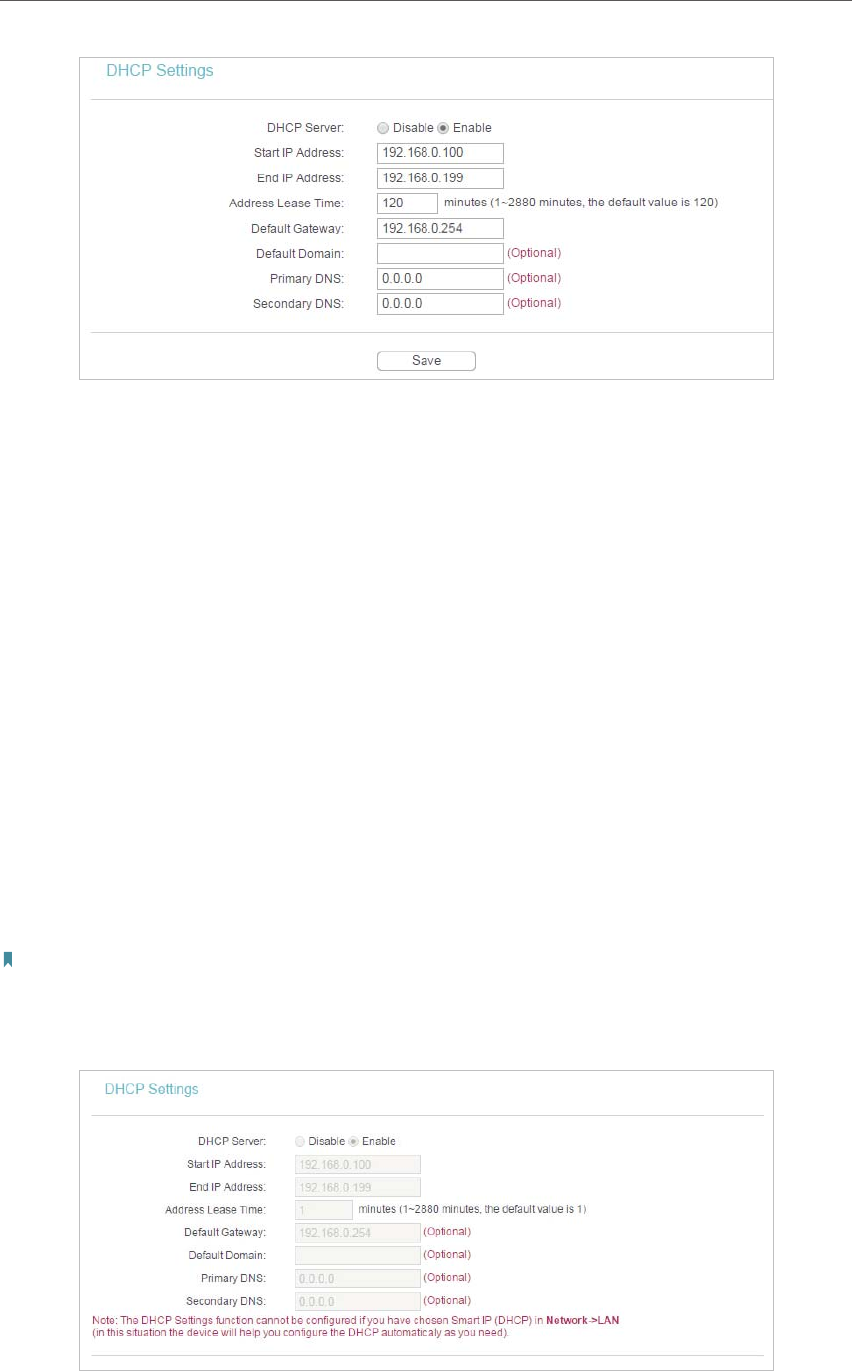
4. 3. 2. DHCP Settings
1. Visit http://tplinkap.net, and log in using admin (all lowercase) for both Username and Password.
2. Go to Network > DHCP Settings.
3. Specify DHCP server settings and click Save.
25
Chapter 4
• DHCP Server - Enable or disable the DHCP server. If disabled, you must have another
DHCP server within your network or else you must configure the computer manually.
• Start IP Address - Specify an IP address for the DHCP Server to start with when
assigning IP addresses. 192.168.0.100 is the default start address.
• End IP Address - Specify an IP address for the DHCP Server to end with when assigning
IP addresses. 192.168.0.199 is the default end address.
• Address Lease Time - The Address Lease Time is the amount of time a network user
will be allowed to connect to the access point with the current dynamic IP Address.
When time is up, the user will be automatically assigned a new dynamic IP address.
The range of the time is 1 ~ 2880 minutes. The default value is 120.
• Default Gateway (Optional) - It is suggested to input the IP address of the LAN port of
the access point. The default value is 192.168.0.254.
• Default Domain (Optional) - Input the domain name of your network.
• Primary DNS (Optional) - Input the DNS IP address provided by your ISP.
• Secondary DNS (Optional) - Input the IP address of another DNS server if your ISP
provides two DNS servers.
Note:
• To use the DHCP server function of the access point, you must configure all computers on the LAN as
Obtain an IP Address automatically.
• When you choose Smart IP (DHCP) in Network > LAN, the DHCP Server function will be disabled. You will
see the page as below.
26
Chapter 4
4. 3. 3. DHCP Client List
1. Visit http://tplinkap.net, and log in using admin (all lowercase) for both Username and Password.
2. Go to
DHCP > DHCP Client List to view the information of the clients connected to the access
point.
• Client Name - The name of the DHCP client.
• MAC Address - The MAC address of the DHCP client.
• Assigned IP - The IP address that the access point has allocated to the DHCP client.
• Lease Time - The time of the DHCP client leased. After the dynamic IP address has
expired, a new dynamic IP address will be automatically assigned to the user.
You cannot change any of the values on this page. To update this page and show the
current attached devices, click Refresh.
4. 4. Wireless
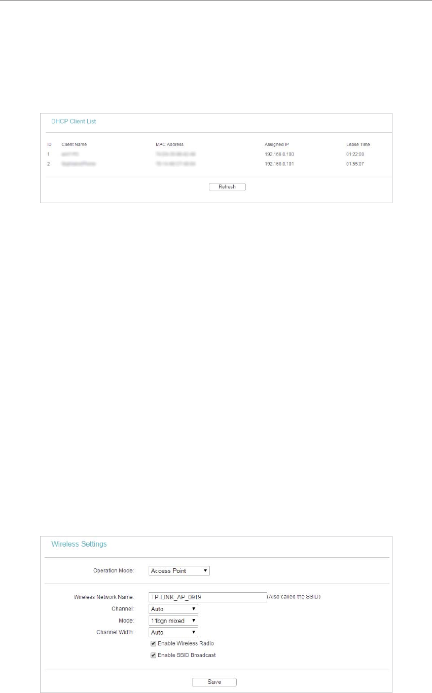
4. 4. 1. Wireless Settings
1. Visit http://tplinkap.net, and log in using admin (all lowercase) for both Username and Password.
2. Go to Wireless > Wireless Settings.
3. Six operation modes are supported here, including Access Point, Multi-SSID, Client, WDS
Repeater, Universal Repeater and Bridge with AP.
Access Point Mode

27
Chapter 4
• Wireless Network Name - Identifies your wireless network name. Create a name up to
32 characters and make sure all wireless points in the wireless network with the same
SSID. The default SSID is TP-LINK_AP_XXXX (XXXX indicates the last unique four
characters of each device’s MAC address). This value is case-sensitive. For example,
TEST is NOT the same as test.
• Channel - Determines the operating frequency to be used. It is not necessary to
change the wireless channel unless you notice interference problems with another
nearby access point.
• Mode - Select the desired wireless mode. The options are:
• 11b only - Only 802.11b wireless stations can connect to the device.
• 11g only - Only 802.11g wireless stations can connect to the device.
• 11n only - Only 802.11n wireless stations can connect to the device.
• 11bg mixed - Both 802.11b and 802.11g wireless stations can connect to the
device.
• 11bgn mixed - All 802.11b, 802.11g and 802.11n wireless stations can connect
to the device.
• Channel Width - Determines the channel width to be used. It is unnecessary to change
the default value unless required.
• Enable Wireless Radio - Select or deselect this check box to allow or deny wireless
stations to access the device.
• Enable SSID Broadcast - Select or deselect this check box to allow or deny the device
to broadcast its name (SSID) on the air. If it’s allowed, when wireless clients survey the
local area for wireless networks to associate with, they will detect the SSID broadcast
by the device.
Note:
To apply any settings you have altered on the page, please click the Save button, and then you will be reminded to reboot
the device.
Multi-SSID Mode

28
Chapter 4
• Enable VLAN - Check this box and then you can change the VLAN ID of each SSID. If
you want to configure the Guest and Internal networks on VLAN, the switch you are
using must support VLAN. As a prerequisite step, configure a port on the switch for
handling VLAN tagged packets as described in the IEEE802.1Q standard, and enable
this field.
• SSID (1-4) - Up to four SSIDs for each BSS (Basic Service Set) can be entered in the
filed SSID1 ~ SSID4. The name can be up to 32 characters. The same name (SSID)
must be assigned to all wireless devices in your network. If Enable VLAN is checked,
the wireless stations connecting to SSID of different VLANID can not communicate
with each other.
• VLAN ID (1-4) - Provide a number between 1 and 4095 for VLAN. This will cause the
device to send packets with VLAN tags. The switch connecting with the device must
support VLAN IEEE802.1Q frames. The wireless stations connecting to the SSID of
a specified VLAN ID can communicate with the PC connecting to the port with the
same VLAN ID on the Switch.
• Channel - Determines the operating frequency to be used. It is not necessary to
change the wireless channel unless you notice interference problems with another
nearby access point.
• Mode - This field determines the wireless mode which the device works on.
• 11b only - Only 802.11b wireless stations can connect to the device.
• 11g only - Only 802.11g wireless stations can connect to the device.
• 11n only - Only 802.11n wireless stations can connect to the device.
• 11bg mixed - Both 802.11b and 802.11g wireless stations can connect to the
device.
• 11bgn mixed - All 802.11b, 802.11g and 802.11n wireless stations can connect
to the device.
• Channel Width - Determines the channel width to be used. It is unnecessary to change
the default value unless required.
• Enable Wireless Radio - Select or deselect this check box to allow or deny wireless
stations to access the device.
• Enable SSID Broadcast - Select or deselect this check box to allow or deny the device
to broadcast its name (SSID) on the air. If it’s allowed, when wireless clients survey the
local area for wireless networks to associate with, they will detect the SSID broadcast
by the device.
Note:
To apply any settings you have altered on the page, please click the Save button, and then you will be reminded to reboot
the device.
29
Chapter 4
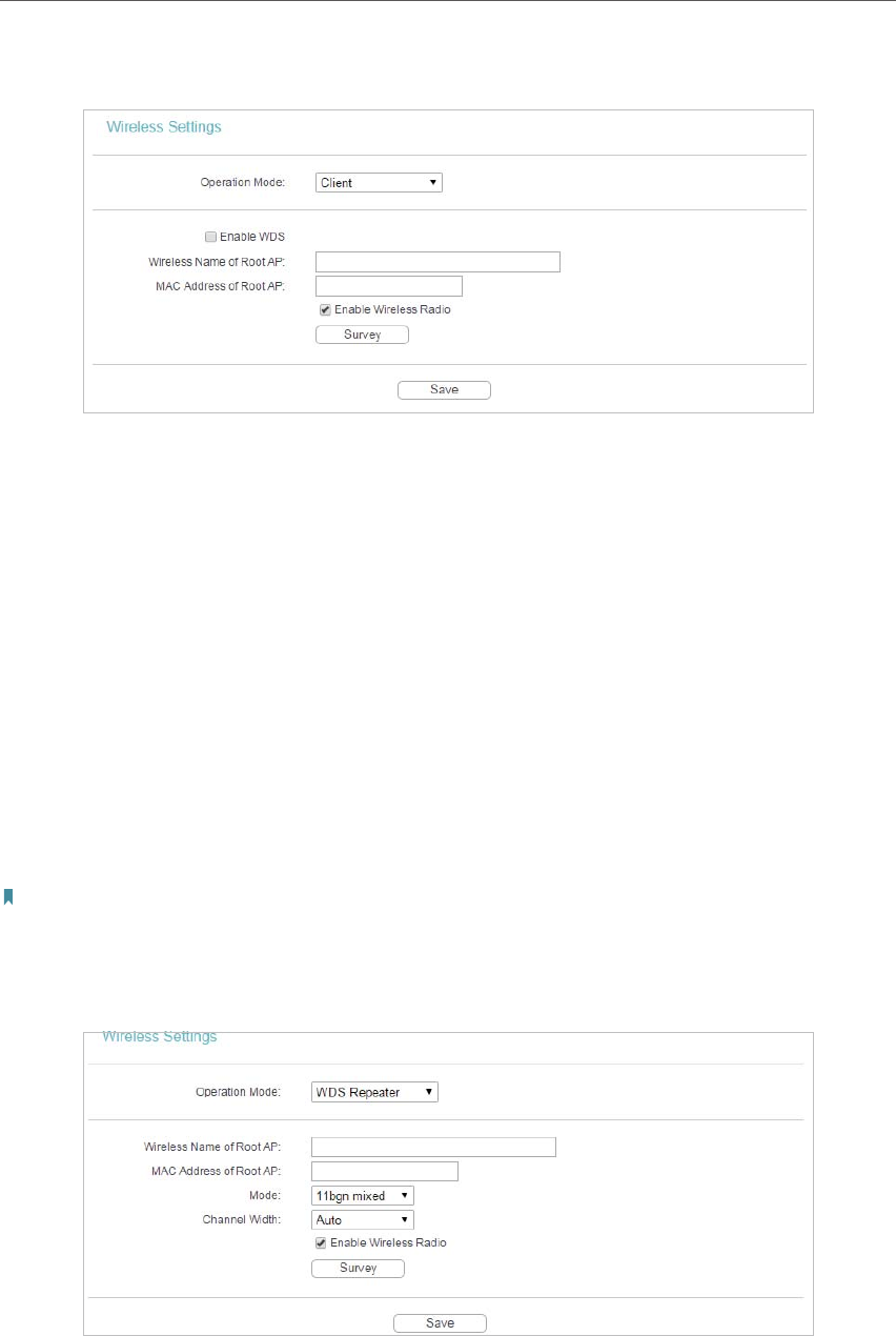
Client Mode
• Enable WDS - The AP client can connect to AP with WDS enabled or disabled. If WDS
is enabled, all traffic from wired networks will be forwarded in the format of WDS
frames consisting of four address fields. If WDS is disabled, three address frames are
used. If your AP supports WDS well, please enable this option.
• Wireless Name of Root AP - If you select the radio button before Wireless Name of
Root AP, the AP client will connect to the AP according to SSID. Enter the SSID of AP
that you want to access.
• MAC Address of Root AP - If you select the radio button before MAC Address of
Root AP, the AP client will connect to the AP according MAC address. Enter the MAC
address of AP that you want to access.
• Enable Wireless Radio - Select or deselect this check box to allow or deny wireless
stations to access the device.
• Click the
Survey button to detect the SSIDs in the local area.
Note:
To apply any settings you have altered on the page, please click the Save button, and then you will be reminded to reboot
the device.
WDS Repeater Mode
• Wireless Name of Root AP - If you select the radio button before Wireless Name of
Root AP, the AP client will connect to the AP according to SSID. Enter the SSID of AP
that you want to access.
30
Chapter 4
• MAC Address of Root AP - If you select the radio button before MAC Address of
Root AP, the AP client will connect to the AP according MAC address. Enter the MAC
address of AP that you want to access.
• Mode - Select the desired wireless mode. The options are:
• 11b only - Only 802.11b wireless stations can connect to the device.
• 11g only - Only 802.11g wireless stations can connect to the device.
• 11n only - Only 802.11n wireless stations can connect to the device.
• 11bg mixed - Both 802.11b and 802.11g wireless stations can connect to the
device.
• 11bgn mixed - All 802.11b, 802.11g and 802.11n wireless stations can connect
to the device.
• Channel Width - Determines the channel width to be used. It is unnecessary to change
the default value unless required.
• Enable Wireless Radio - Select or deselect this check box to allow or deny wireless
stations to access the device.
Click the Survey button to detect the SSIDs in the local area.
Note:
To apply any settings you have altered on the page, please click the Save button, and then you will be reminded to reboot
the device.
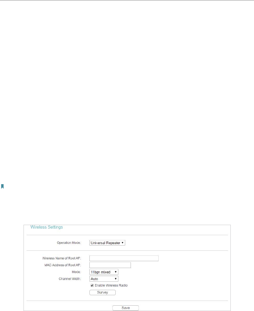
Universal Repeater Mode
• Wireless Name of Root AP - If you select the radio button before Wireless Name of
Root AP, the AP client will connect to the AP according to SSID. Enter the SSID of AP
that you want to access.
• MAC Address of Root AP - If you select the radio button before MAC Address of
Root AP, the AP client will connect to the AP according MAC address. Enter the MAC
address of AP that you want to access.
• Mode - Select the desired wireless mode. The options are:
• 11b only - Only 802.11b wireless stations can connect to the device.
• 11g only - Only 802.11g wireless stations can connect to the device.
31
Chapter 4
• 11n only - Only 802.11n wireless stations can connect to the device.
• 11bg mixed - Both 802.11b and 802.11g wireless stations can connect to the
device.
• 11bgn mixed - All 802.11b, 802.11g and 802.11n wireless stations can connect
to the device.
• Channel Width - Determines the channel width to be used. It is unnecessary to change
the default value unless required.
• Enable Wireless Radio - Select or deselect this check box to allow or deny wireless
stations to access the device.
Click the Survey button to detect the SSIDs in the local area.
Note:
To apply any settings you have altered on the page, please click the Save button, and then you will be reminded to reboot
the device.
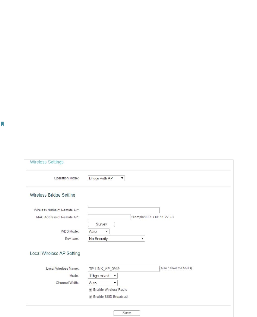
Bridge with AP Mode
Wireless Bridge Settting
• Wireless Name of Remote AP - If you select the radio button before Wireless Name of
Remote AP, the AP client will connect to the AP according to SSID. Enter the SSID of
AP that you want to access.
• MAC Address of Remote AP - If you select the radio button before MAC Address of
Remote AP, the AP client will connect to the AP according MAC address. Enter the
MAC address of AP that you want to access.
Click the Survey button to detect the SSIDs in the local area.

32
Chapter 4
• Key type - This option should be chosen according to the AP’s security configuration.
It is recommended that the security type is the same as your AP’s security type.
• Password - If the Remote AP that your device is going to connect needs password,
you need to fill the password in this blank.
Local Wireless AP Setting
• Local Wireless Name - Name for the AP.
• Mode - This field determines the wireless mode which the device works on.
• 11b only - Only 802.11b wireless stations can connect to the device.
• 11g only - Only 802.11g wireless stations can connect to the device.
• 11n only - Only 802.11n wireless stations can connect to the device.
• 11bg mixed - Both 802.11b and 802.11g wireless stations can connect to the
device.
• 11bgn mixed - All 802.11b, 802.11g and 802.11n wireless stations can connect
to the device.
• Channel Width - Determines the channel width to be used. It is unnecessary to change
the default value unless required.
• Enable Wireless Radio - Select or deselect this check box to allow or deny wireless
stations to access the device.
• Enable SSID Broadcast - Select or deselect this check box to allow or deny the device
to broadcast its name (SSID) on the air. If it’s allowed, when wireless clients survey the
local area for wireless networks to associate with, they will detect the SSID broadcast
by the device.
Note:
To apply any settings you have altered on the page, please click the Save button, and then you will be reminded to reboot
the device.
4. 4. 2. Wireless Security
1. Visit http://tplinkap.net, and log in using admin (all lowercase) for both Username and Password.
2. Go to Wireless > Wireless Security.
3. Configure the security settings of your wireless network and click Save. The security options
are different for different operation mode.
33
Chapter 4
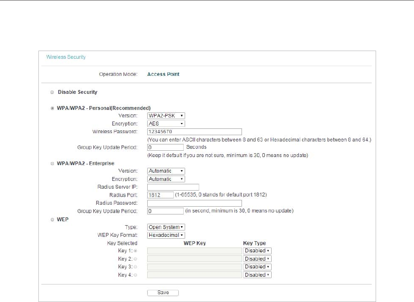
Access Point
• Disable Security - Check this box radio button to disable wireless security. If disabled,
the wireless stations will be able to connect this device without encryption. It is
strongly recommended that you choose one of the security types to enable security.
• WPA/WPA2-Personal(Recommended) - Select WPA/WPA2 based on Radius Server.
• Version - You can select one of following versions.
• Automatic (Recommended) - Select WPA-Personal or WPA2-Personal automatically based on the
wireless station’s capability and request.
• WPA-PSK - Pre-shared key of WPA.
• WPA2-PSK - Pre-shared key of WPA2.
• Encryption - You can select either Automatic(Recommended), TKIP or AES.
• Wireless Password - You can enter ASCII or Hexadecimal characters. For
Hexadecimal, the length should be between 8 and 64 characters; for ASCII, the
length should be between 8 and 63 characters.
• Group Key Update Period - Specify the group key update interval in seconds.
The value can be either 0 or at least 30. Enter 0 to disable the update.
• WPA/WPA2-Enterprise - Select WPA/WPA2 based on Radius Server.
• Version - You can select one of following versions.
• Automatic - Select WPA or WPA2 automatically based on the wireless station’s capability and request.
• WPA - Wi-Fi Protected Access.
• WPA2 - WPA version 2.

34
Chapter 4
• Encryption - You can select either Automatic, TKIP or AES.
• Radius Server IP - Enter the IP address of the Radius Server.
• Radius Port - Enter the port used by radius service.
• Radius Password - Enter the password for the Radius Server.
• Group Key Update Period - Specify the group key update interval in seconds.
The value can be either 0 or at least 30. Enter 0 to disable the update.
• WEP - Select 802.11 WEP security.
• Type - You can select one of following types.
• Automatic - Select Shared Key or Open System authentication type automatically based on the wireless
station’s capability and request.
• Shared Key - Select 802.11 Shared Key authentication type.
• Open System - Select 802.11 Open System authentication.
• WEP Key Format - You can select ASCII or Hexadecimal format. ASCII format
stands for any combination of keyboard characters in the specified length.
Hexadecimal format stands for any combination of hexadecimal digits (0-9, a-f,
A-F) in the specified length.
• WEP Key - Select which of the four keys will be used and enter the matching
WEP key information for your network in the selected key radio button. These
values must be identical on all wireless stations in your network.
• Key Type - You can select the WEP key length (64-bit, or 128-bit, or 152-bit.) for
encryption. “Disabled” means this WEP key entry is invalid.
• For 64-bit encryption - You can enter 10 hexadecimal digits (any combination of 0-9, a-f, A-F, zero key is
not permitted) or 5 ASCII characters.
• For
128-bit encryption - You can enter 26 hexadecimal digits (any combination of 0-9, a-f, A-F, zero key is
not permitted) or 13 ASCII characters.
• For
152-bit encryption - You can enter 32 hexadecimal digits (any combination of 0-9, a-f, A-F, zero key is
not permitted) or 16 ASCII characters.
Note:
• If you do not set the key, the wireless security function is still disabled even if you have selected Shared
Key as Authentication Type.
• You will be reminded to reboot the device after clicking the Save button.
35
Chapter 4
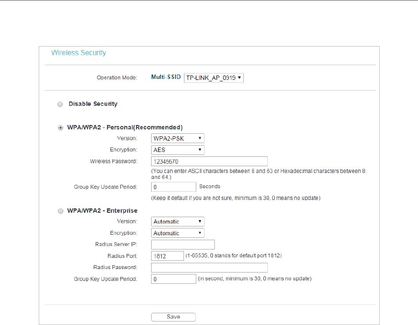
Multi-SSID
You can choose which SSID to configure wireless security settings for in the blank
behind Operation Mode.
• Disable Security - Check this box radio button to disable wireless security. If disabled,
the wireless stations will be able to connect this device without encryption. It is
strongly recommended that you choose one of the security types to enable security.
• WPA/WPA2-Personal (Recommended) - Select WPA/WPA2 based on Radius Server.
• Version - You can select one of following versions.
• Automatic (Recommended) - Select WPA-Personal or WPA2-Personal automatically based on the
wireless station’s capability and request.
• WPA-PSK - Pre-shared key of WPA.
• WPA2-PSK - Pre-shared key of WPA2.
• Encryption - You can select either Automatic(Recommended), TKIP or AES.
• Wireless Password - You can enter ASCII or Hexadecimal characters. For
Hexadecimal, the length should be between 8 and 64 characters; for ASCII, the
length should be between 8 and 63 characters.
• Group Key Update Period - Specify the group key update interval in seconds.
The value can be either 0 or at least 30. Enter 0 to disable the update.
• WPA/WPA2-Enterprise - Select WPA/WPA2 based on Radius Server.
• Version - You can select one of following versions.
36
Chapter 4
• Automatic - Select WPA or WPA2 automatically based on the wireless station’s capability and request.
• WPA - Wi-Fi Protected Access.
• WPA2 - WPA version 2.
• Encryption - You can select either Automatic, TKIP or AES.
• Radius Server IP - Enter the IP address of the Radius Server.
• Radius Port - Enter the port used by radius service.
• Radius Password - Enter the password for the Radius Server.
• Group Key Update Period - Specify the group key update interval in seconds. The
value can be either 0 or at least 30. Enter 0 to disable the update.
Note:
You will be reminded to reboot the device after clicking the Save button.
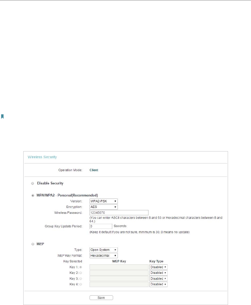
Client
• Disable Security - Check this box radio button to disable wireless security. If disabled,
the wireless stations will be able to connect this device without encryption. It is
strongly recommended that you choose one of the security types to enable security.
• WPA/WPA2-Personal (Recommended) - Select WPA/WPA2 based on Radius Server.
• Version - You can select one of following versions.
• Automatic (Recommended) - Select WPA-Personal or WPA2-Personal automatically based on the
wireless station’s capability and request.
• WPA-PSK - Pre-shared key of WPA.

37
Chapter 4
• WPA2-PSK - Pre-shared key of WPA2.
• Encryption - You can select either Automatic(Recommended), TKIP or AES.
• Wireless Password - You can enter ASCII or Hexadecimal characters. For
Hexadecimal, the length should be between 8 and 64 characters; for ASCII, the
length should be between 8 and 63 characters.
• Group Key Update Period - Specify the group key update interval in seconds.
The value can be either 0 or at least 30. Enter 0 to disable the update.
• WEP - Select 802.11 WEP security.
• Type - You can select one of following types.
• Automatic - Select Shared Key or Open System authentication type automatically based on the wireless
station’s capability and request.
• Shared Key - Select 802.11 Shared Key authentication type.
• Open System - Select 802.11 Open System authentication.
• WEP Key Format - You can select ASCII or Hexadecimal format. ASCII format
stands for any combination of keyboard characters in the specified length.
Hexadecimal format stands for any combination of hexadecimal digits (0-9, a-f,
A-F) in the specified length.
• WEP Key - Select which of the four keys will be used and enter the matching
WEP key information for your network in the selected key radio button. These
values must be identical on all wireless stations in your network.
• Key Type - You can select the WEP key length (64-bit, or 128-bit, or 152-bit.) for
encryption. “Disabled” means this WEP key entry is invalid.
• For 64-bit encryption - You can enter 10 hexadecimal digits (any combination of 0-9, a-f, A-F, zero key is
not permitted) or 5 ASCII characters.
• For
128-bit encryption - You can enter 26 hexadecimal digits (any combination of 0-9, a-f, A-F, zero key is
not permitted) or 13 ASCII characters.
• For
152-bit encryption - You can enter 32 hexadecimal digits (any combination of 0-9, a-f, A-F, zero key is
not permitted) or 16 ASCII characters.
Note:
• If you do not set the key, the wireless security function is still disabled even if you have selected Shared
Key as Authentication Type.
• You will be reminded to reboot the device after clicking the Save button.
38
Chapter 4
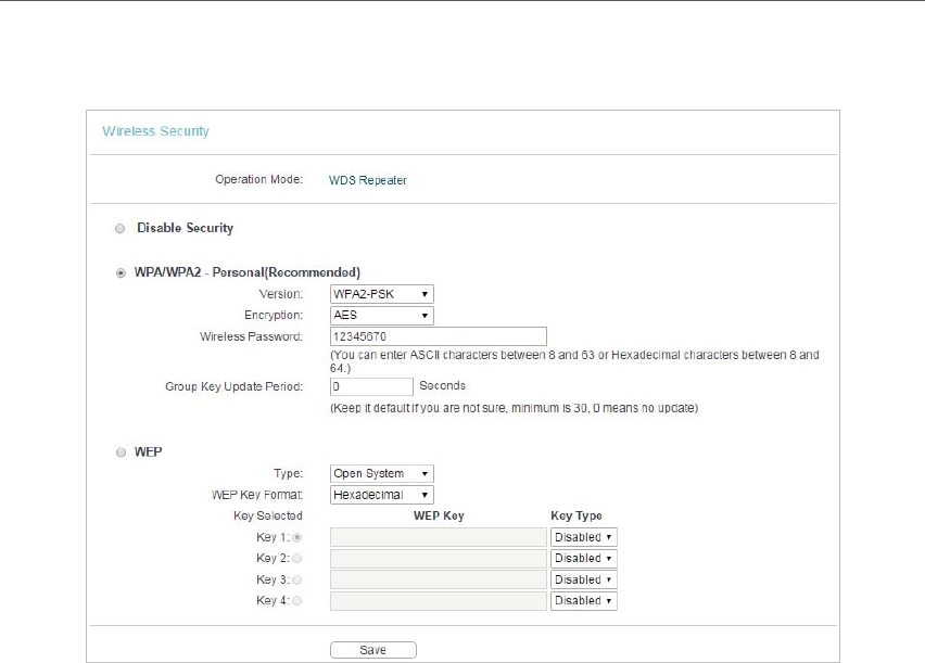
WDS Repeater
• Disable Security - Check this box radio button to disable wireless security. If disabled,
the wireless stations will be able to connect this device without encryption. It is
strongly recommended that you choose one of the security types to enable security.
• WPA/WPA2-Personal (Recommended) - Select WPA/WPA2 based on Radius Server.
• Version - You can select one of following versions.
• Automatic (Recommended) - Select WPA-Personal or WPA2-Personal automatically based on the
wireless station’s capability and request.
• WPA-PSK - Pre-shared key of WPA.
• WPA2-PSK - Pre-shared key of WPA2.
• Encryption - You can select either Automatic(Recommended), TKIP or AES.
• Wireless Password - You can enter ASCII or Hexadecimal characters. For
Hexadecimal, the length should be between 8 and 64 characters; for ASCII, the
length should be between 8 and 63 characters.
• Group Key Update Period - Specify the group key update interval in seconds.
The value can be either 0 or at least 30. Enter 0 to disable the update.
• WEP - Select 802.11 WEP security.
• Type - You can select one of following types.
• Automatic - Select Shared Key or Open System authentication type automatically based on the wireless
station’s capability and request.
• Shared Key - Select 802.11 Shared Key authentication type.
• Open System - Select 802.11 Open System authentication.
39
Chapter 4
• WEP Key Format - You can select ASCII or Hexadecimal format. ASCII format
stands for any combination of keyboard characters in the specified length.
Hexadecimal format stands for any combination of hexadecimal digits (0-9, a-f,
A-F) in the specified length.
• WEP Key - Select which of the four keys will be used and enter the matching
WEP key information for your network in the selected key radio button. These
values must be identical on all wireless stations in your network.
• Key Type - You can select the WEP key length (64-bit, or 128-bit, or 152-bit.) for
encryption. “Disabled” means this WEP key entry is invalid.
• For 64-bit encryption - You can enter 10 hexadecimal digits (any combination of 0-9, a-f, A-F, zero key is
not permitted) or 5 ASCII characters.
• For
128-bit encryption - You can enter 26 hexadecimal digits (any combination of 0-9, a-f, A-F, zero key is
not permitted) or 13 ASCII characters.
• For 152-bit encryption - You can enter 32 hexadecimal digits (any combination of 0-9, a-f, A-F, zero key is
not permitted) or 16 ASCII characters.
Note:
• If you do not set the key, the wireless security function is still disabled even if you have selected Shared
Key as Authentication Type.
• You will be reminded to reboot the device after clicking the Save button.
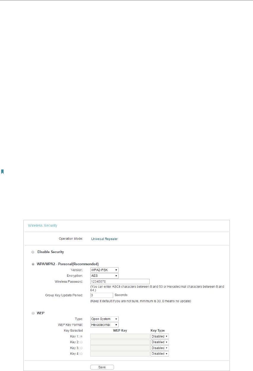
Universal Repeater
• Disable Security - Check this box radio button to disable wireless security. If disabled,
the wireless stations will be able to connect this device without encryption. It is
strongly recommended that you choose one of the security types to enable security.

40
Chapter 4
• WPA/WPA2-Personal (Recommended) - Select WPA/WPA2 based on Radius Server.
• Version - You can select one of following versions.
• Automatic (Recommended) - Select WPA-Personal or WPA2-Personal automatically based on the
wireless station’s capability and request.
• WPA-PSK - Pre-shared key of WPA.
• WPA2-PSK - Pre-shared key of WPA2.
• Encryption - You can select either Automatic(Recommended), TKIP or AES.
• Wireless Password - You can enter ASCII or Hexadecimal characters. For
Hexadecimal, the length should be between 8 and 64 characters; for ASCII, the
length should be between 8 and 63 characters.
• Group Key Update Period - Specify the group key update interval in seconds.
The value can be either 0 or at least 30. Enter 0 to disable the update.
• WEP - Select 802.11 WEP security.
• Type - You can select one of following types.
• Automatic - Select Shared Key or Open System authentication type automatically based on the wireless
station’s capability and request.
• Shared Key - Select 802.11 Shared Key authentication type.
• Open System - Select 802.11 Open System authentication.
• WEP Key Format - You can select ASCII or Hexadecimal format. ASCII format
stands for any combination of keyboard characters in the specified length.
Hexadecimal format stands for any combination of hexadecimal digits (0-9, a-f,
A-F) in the specified length.
• WEP Key - Select which of the four keys will be used and enter the matching
WEP key information for your network in the selected key radio button. These
values must be identical on all wireless stations in your network.
• Key Type - You can select the WEP key length (64-bit, or 128-bit, or 152-bit.) for
encryption. “Disabled” means this WEP key entry is invalid.
• For 64-bit encryption - You can enter 10 hexadecimal digits (any combination of 0-9, a-f, A-F, zero key is
not permitted) or 5 ASCII characters.
• For
128-bit encryption - You can enter 26 hexadecimal digits (any combination of 0-9, a-f, A-F, zero key is
not permitted) or 13 ASCII characters.
• For 152-bit encryption - You can enter 32 hexadecimal digits (any combination of 0-9, a-f, A-F, zero key is
not permitted) or 16 ASCII characters.
Note:
• If you do not set the key, the wireless security function is still disabled even if you have selected Shared
Key as Authentication Type.
• You will be reminded to reboot the device after clicking the Save button.
41
Chapter 4
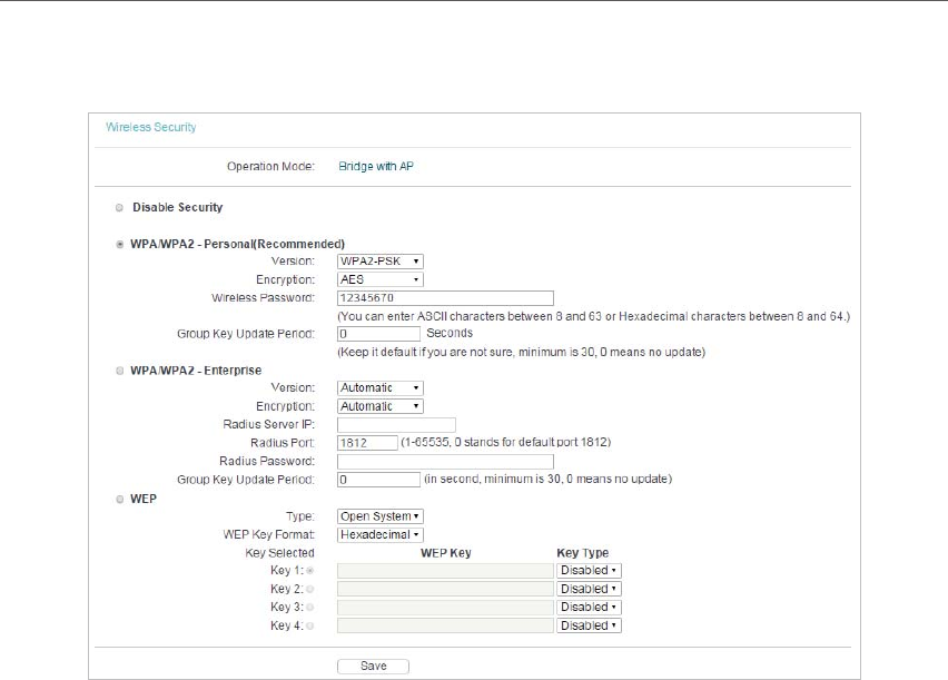
Bridge with AP
• Disable Security - Check this box radio button to disable wireless security. If disabled,
the wireless stations will be able to connect this device without encryption. It is
strongly recommended that you choose one of the security types to enable security.
• WPA/WPA2-Personal(Recommended) - Select WPA/WPA2 based on Radius Server.
• Version - You can select one of following versions.
• Automatic (Recommended) - Select WPA-Personal or WPA2-Personal automatically based on the
wireless station’s capability and request.
• WPA-PSK - Pre-shared key of WPA.
• WPA2-PSK - Pre-shared key of WPA2.
• Encryption - You can select either Automatic(Recommended), TKIP or AES.
• Wireless Password - You can enter ASCII or Hexadecimal characters. For
Hexadecimal, the length should be between 8 and 64 characters; for ASCII, the
length should be between 8 and 63 characters.
• Group Key Update Period - Specify the group key update interval in seconds.
The value can be either 0 or at least 30. Enter 0 to disable the update.
• WPA/WPA2-Enterprise - Select WPA/WPA2 based on Radius Server.
• Version - You can select one of following versions.
• Automatic - Select WPA or WPA2 automatically based on the wireless station’s capability and request.
• WPA - Wi-Fi Protected Access.
• WPA2 - WPA version 2.
• Encryption - You can select either Automatic, TKIP or AES.

42
Chapter 4
• Radius Server IP - Enter the IP address of the Radius Server.
• Radius Port - Enter the port used by radius service.
• Radius Password - Enter the password for the Radius Server.
• Group Key Update Period - Specify the group key update interval in seconds.
The value can be either 0 or at least 30. Enter 0 to disable the update.
• WEP - Select 802.11 WEP security.
• Type - You can select one of following types.
• Automatic - Select Shared Key or Open System authentication type automatically based on the wireless
station’s capability and request.
• Shared Key - Select 802.11 Shared Key authentication type.
• Open System - Select 802.11 Open System authentication.
• WEP Key Format - You can select ASCII or Hexadecimal format. ASCII format
stands for any combination of keyboard characters in the specified length.
Hexadecimal format stands for any combination of hexadecimal digits (0-9, a-f,
A-F) in the specified length.
• WEP Key - Select which of the four keys will be used and enter the matching
WEP key information for your network in the selected key radio button. These
values must be identical on all wireless stations in your network.
• Key Type - You can select the WEP key length (64-bit, or 128-bit, or 152-bit.) for
encryption. “Disabled” means this WEP key entry is invalid.
• For 64-bit encryption - You can enter 10 hexadecimal digits (any combination of 0-9, a-f, A-F, zero key is
not permitted) or 5 ASCII characters.
• For
128-bit encryption - You can enter 26 hexadecimal digits (any combination of 0-9, a-f, A-F, zero key is
not permitted) or 13 ASCII characters.
• For
152-bit encryption - You can enter 32 hexadecimal digits (any combination of 0-9, a-f, A-F, zero key is
not permitted) or 16 ASCII characters.
Note:
• If you do not set the key, the wireless security function is still disabled even if you have selected Shared
Key as Authentication Type.
• You will be reminded to reboot the device after clicking the Save button.
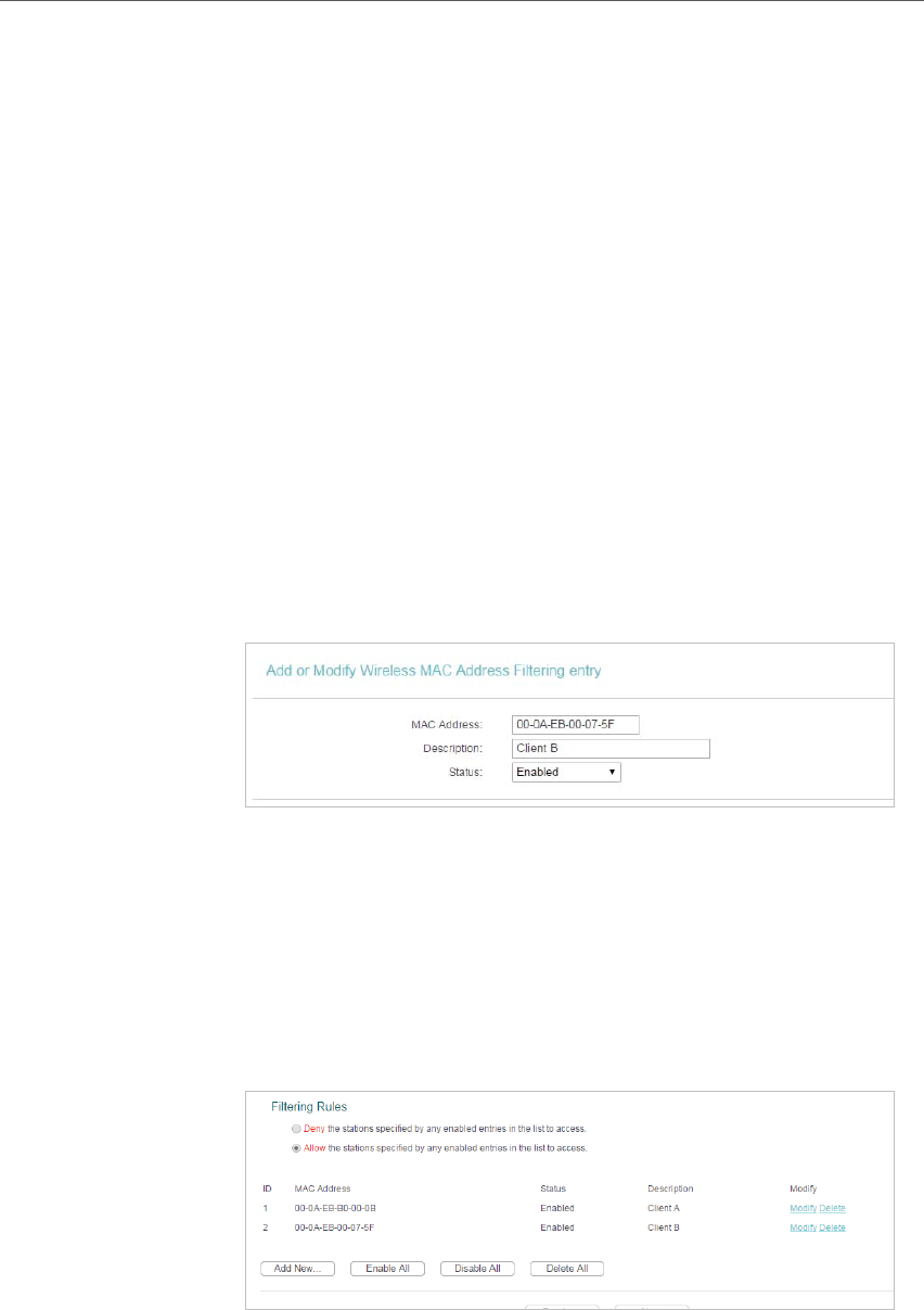
4. 4. 3. Wireless MAC Filtering
Wireless MAC Filtering is used to deny or allow specific wireless client devices to access
your network by their MAC addresses. This function is not available when the operation
is set to Client. As the configuration is the same in each operation mode, here we just
take the Access Point for example.
43
Chapter 4
Deny or allow specific wireless client devices to access my
network by their MAC addresses.
For example, you want the wireless client A with the MAC
address 00-0A-EB-B0-00-0B and the wireless client B with the
MAC address 00-0A-EB-00-07-5F to access the access point,
but other wireless clients cannot access the access point.
1. Visit http://tplinkap.net, and log in using admin (all lowercase)
for both Username and Password.
2. Go to Wireless > Wireless MAC Filtering.
3. Click Enable to enable the Wireless MAC Filtering function.
4. Select Allow the stations specified by any enabled entries in
the list to access as the filtering rule.
5. Delete all or disable all entries if there are any entries already.
6. Click Add New and fill in the blank.
1 ) Enter the MAC address 00-0A-EB-B0-00-0B/00-0A-EB-
00-07-5F in the MAC Address field.
2 ) Enter wireless client A/B in the Description field.
3 ) Select Enabled in the Status drop-down list.
4 ) Click Save and click Back.
7. The configured filtering rules should be listed as the picture
shows below.
Now only client A and client B can access your network.
I want to:
Done!
44
Chapter 4
4. 4. 4. Wireless Advanced
The configuration for each operation mode is almost the same, we take Access Point
mode for example here.
1. Visit http://tplinkap.net, and log in using admin (all lowercase) for both Username and Password.
2. Go to Wireless > Wireless Advanced.
3. Configure the advanced settings of your wireless network and click Save.
Note:
If you are not familiar with the setting items on this page, it’s strongly recommended to keep the provided default values;
otherwise it may result in lower wireless network performance.
• Transmit Power - Select High, Middle or Low which you would like to specify for the
access point. High is the default setting and recommended.
• Beacon Interval - Enter a value between 40-1000 milliseconds for Beacon Interval
here. Beacon Interval value determines the time interval of the beacons. The beacons
are the packets sent by the access point to synchronize a wireless network. The
default value is 100.
• RTS Threshold - Here you can specify the RTS (Request to Send) Threshold. If the
packet is larger than the specified RTS Threshold size, the access point will send RTS
frames to a particular receiving station and negotiate the sending of a data frame. The
default value is 2346.
• Fragmentation Threshold - This value is the maximum size determining whether
packets will be fragmented. Setting a low value for the Fragmentation Threshold may
result in poor network performance because of excessive packets. 2346 is the default
setting and is recommended.
• DTIM Interval - This value determines the interval of the Delivery Traffic Indication
Message (DTIM). A DTIM field is a countdown field informing clients of the next
window for listening to broadcast and multicast messages. When the access point
has buffered broadcast or multicast messages for associated clients, it sends the
next DTIM with a DTIM Interval value. You can specify the value between 1-255
45
Chapter 4
Beacon Intervals. The default value is 1, which indicates the DTIM Interval is the same
as Beacon Interval.
• Enable WMM - WMM function can guarantee the packets with high-priority messages
being transmitted preferentially. It is strongly recommended to enable this function.
• Enable Short GI - It is recommended to enable this function, for it will increase the
data capacity by reducing the guard interval time.
• Enable AP Isolation - This function isolates all connected wireless stations so that
wireless stations cannot access each other through WLAN. This function will be
disabled if WDS/Bridge is enabled.
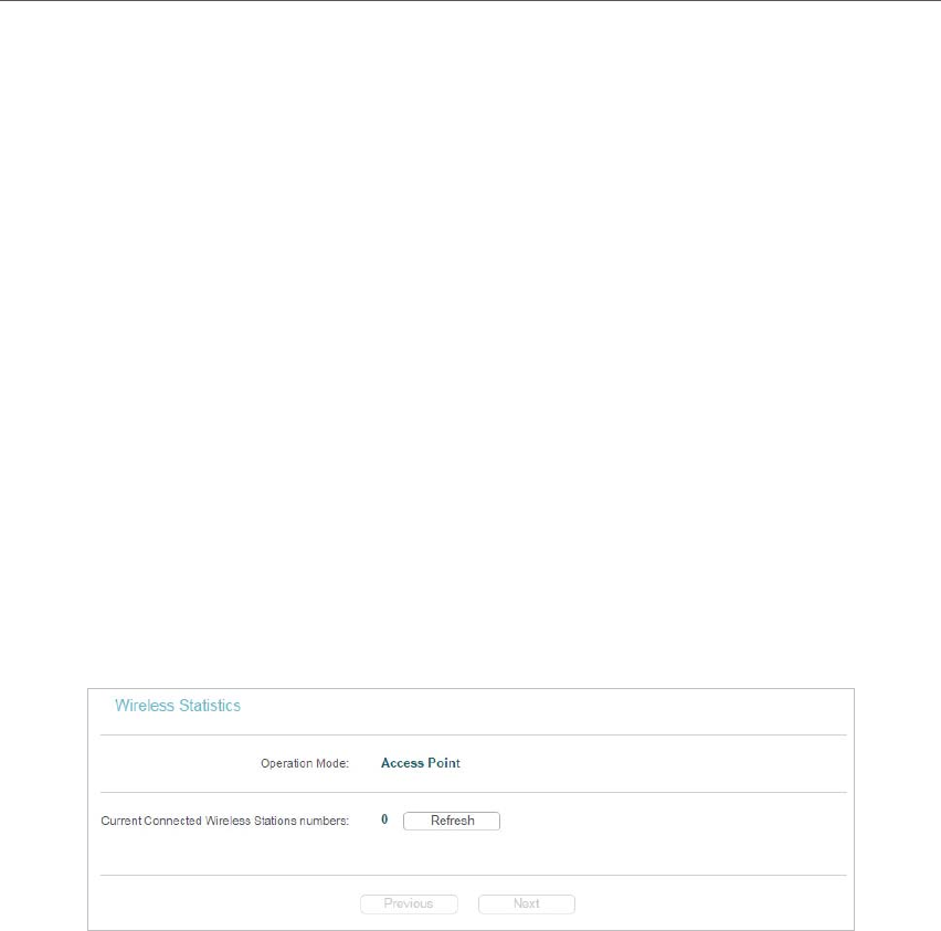
4. 4. 5. Wireless Statistics
The configuration for each operation mode is almost the same, we take Access Point
mode for example here.
1. Visit http://tplinkap.net, and log in using admin (all lowercase) for both Username and Password.
2. Go to Wireless > Wireless Statistics to check the data packets sent and received by each
client device connected to the access point.
• MAC Address - The MAC address of the connected wireless client.
• Current Status - The running status of the connected wireless client.
• Received Packets - Packets received by the wireless client.
• Sent Packets - Packets sent by the wireless client.
• Configure - The button is used for loading the item to the Wireless MAC Filtering list.
• Allow - If the Wireless MAC Filtering function is enabled, click this button to
allow the client to access your network.
• Deny - If the Wireless MAC Filtering function is enabled, click this button to
deny the client to access your network.
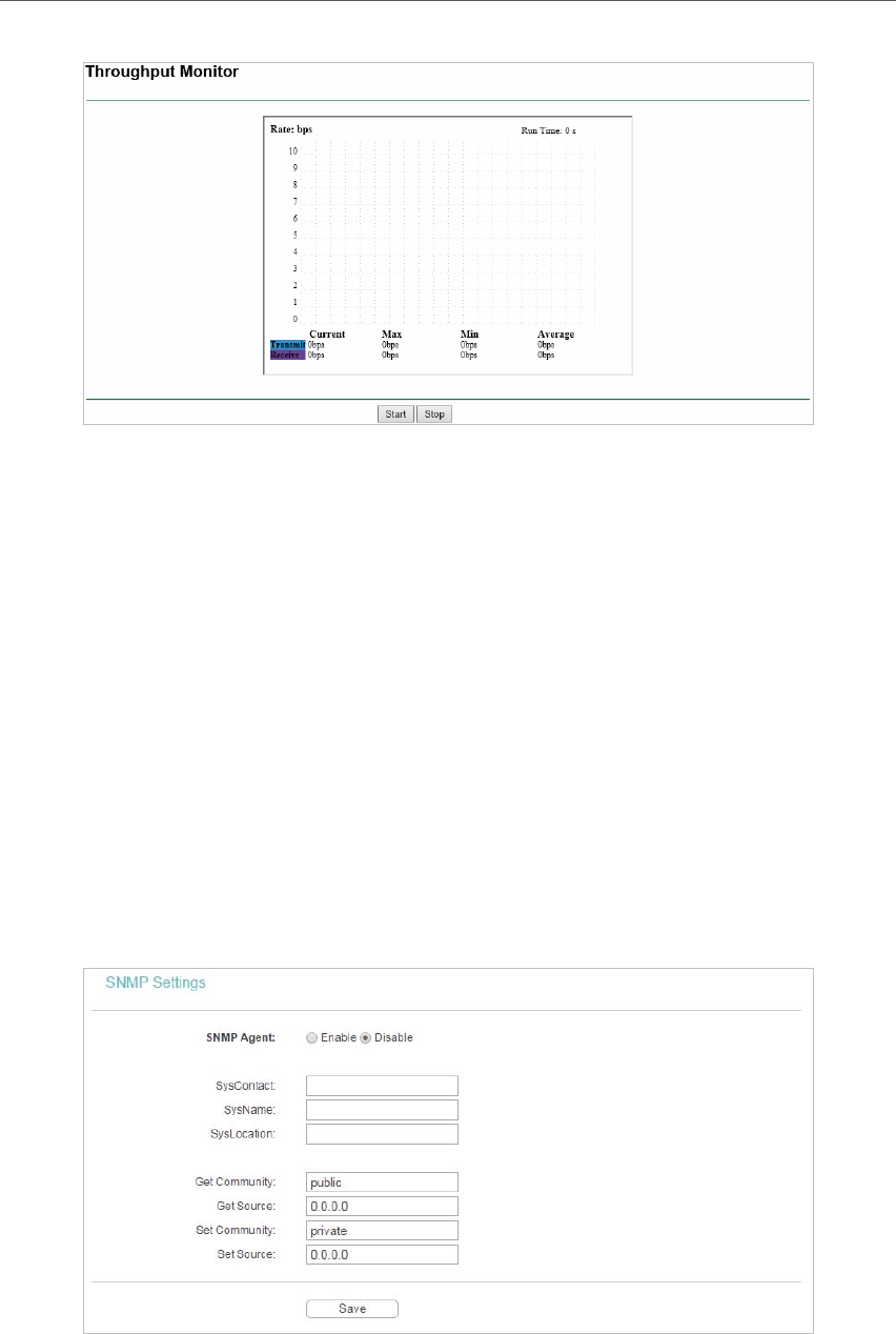
4. 4. 6. Throughput Monitor
1. Visit http://tplinkap.net, and log in using admin (all lowercase) for both Username and Password.
2. Go to Wireless > Throughput Monitor to view the wireless throughput information.
46
Chapter 4
• Rate - The Throughput unit.
• Run Time - How long this function is running.
• Transmit - Wireless transmit rate information.
• Receive - Wireless receive rate information.
Click Start/Stop to start or stop wireless throughput monitor.
4. 5. System Tools
4. 5. 1. SNMP
Simple Network Management Protocol (SNMP) is a popular network monitoring and
management protocol.
1. Visit http://tplinkap.net, and log in using admin (all lowercase) for both Username and Password.
2. Go to System Tools > SNMP.

47
Chapter 4
• SNMP Agent - Select the radio button before Enable will enable this function if you
want to have remote control through SNMPv1/v2 agent with MIB-II. Select the radio
button before Disable will disable this function. The default setting is Disable.
• SysContact - The textual identification of the contact person for this managed node.
• SysName - An administratively-assigned name for this managed node.
• SysLocation - The physical location of this node.
Note:
If you are not familiar with the setting items on this page, it’s strongly recommended to keep the provided default values;
otherwise it may result in lower wireless network performance.
• Get Community - Enter the community name that allows Read-Only access to the
Device’s SNMP information. The community name can be considered a group
password. The default setting is “public”.
• Get Source - Get source defines the IP address or subnet for management systems
that can read information from this ‘get’ community device.
• Set Community - Enter the community name that allows Read/Write access to the
Device’s SNMP information. The community name can be considered a group
password. The default setting is “private”.
• Set Source - Set source defines the IP address or subnet for management systems
that can control this ‘set’ community device.
Note:
A restricted source can be a specific IP address (e.g. 10.10.10.1), or a subnet - represented as IP/BITS (e.g. 10.10.10.0/24).
If an IP Address of 0.0.0.0 is specified, the agent will accept all requests under the corresponding community name.
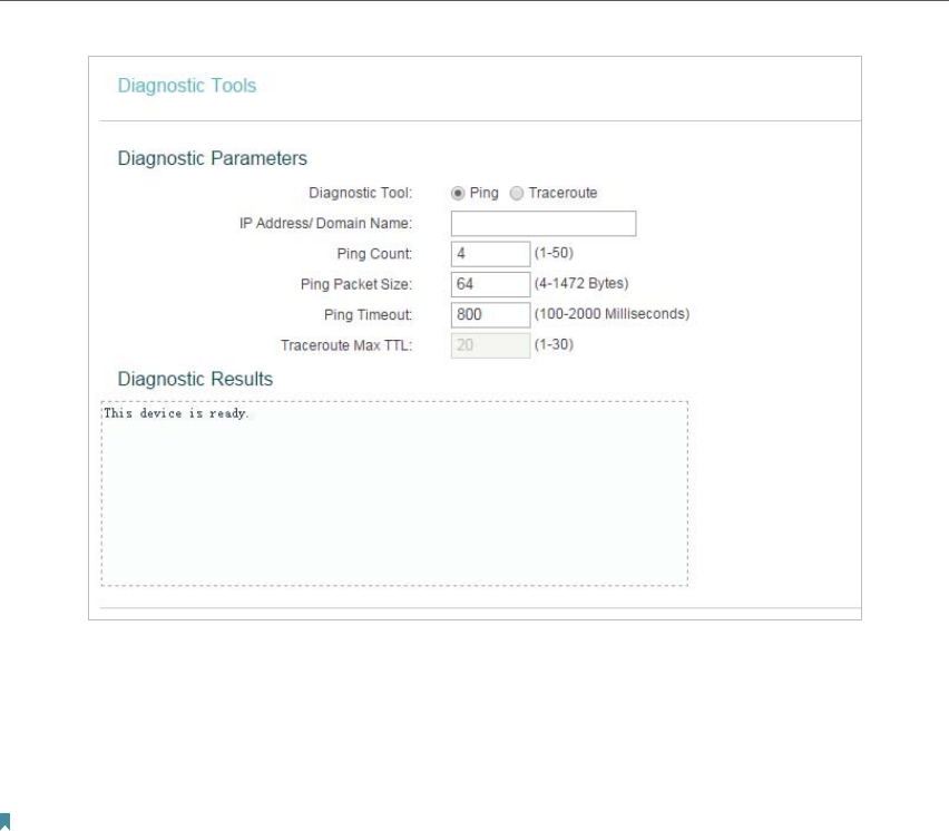
4. 5. 2. Diagnostic
Diagnostic is used to test the connectivity between the access point and the host or
other network devices.
1. Visit http://tplinkap.net, and log in using admin (all lowercase) for both Username and Password.
2. Go to System Tools > Diagnostic.
48
Chapter 4
• Diagnostic Tool - Select one diagnostic tool.
• Ping - This diagnostic tool troubleshoots connectivity, reachability, and name
resolution to a given host or gateway.
• Tracerouter - This diagnostic tool tests the performance of a connection.
Note:
You can use ping/traceroute to test both numeric IP address or domain name. If pinging/tracerouting the IP address is
successful, but pinging/tracerouting the domain name is not, you might have a name resolution problem. In this case,
ensure that the domain name you are specifying can be resolved by using Domain Name System (DNS) queries.
• IP Address/Domain Name - Enter the destination IP address (such as 192.168.0.254)
or Domain name (such as www.tp-link.com).
• Pings Count - The number of Ping packets for a Ping connection.
• Ping Packet Size - The size of Ping packet.
• Ping Timeout - Set the waiting time for the reply of each Ping packet. If there is no
reply in the specified time, the connection is overtime.
• Traceroute Max TTL - The max number of hops for a Traceroute connection.
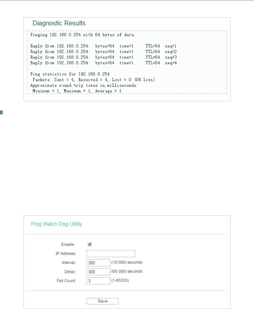
3. Click Start to check the connectivity of the Internet.
4. The Diagnostic Results page displays the diagnosis result. If the result is similar to the
following figure, the connectivity of the Internet is fine.
49
Chapter 4
Note:
Only one user can use this tool at one time. Options “Number of Pings”, “Ping Size” and “Ping Timeout” are used for the
Ping function. Option “Tracert Hops” is used for the Tracert function.
4. 5. 3. Ping Watch Dog
The Ping Watch Dog is dedicated for continuous monitoring of the particular connection
to remote host using the Ping tool. It makes the access point continuously ping a user
defined IP address (it can be the Internet gateway for example). If it is unable to ping
under the user defined constraints, the access point will automatically reboot.
1. Visit http://tplinkap.net, and log in using admin (all lowercase) for both Username and Password.
2. Go to System Tools > Ping Watch Dog. Configure the settings and click Save.
• Enable - Turn on/off Ping Watch Dog.
• IP Address - The IP address of the target host where the Ping Watch Dog Utility is
sending ping packets.
• Interval - Time interval between two ping packets which are sent out continuously.
• Delay - Time delay before first ping packet is sent out when the access point is
restarted.
• Fail Count - Upper limit of the ping packets the access point can drop continuously. If
this value is overrun, the access point will restart automatically.
50
Chapter 4
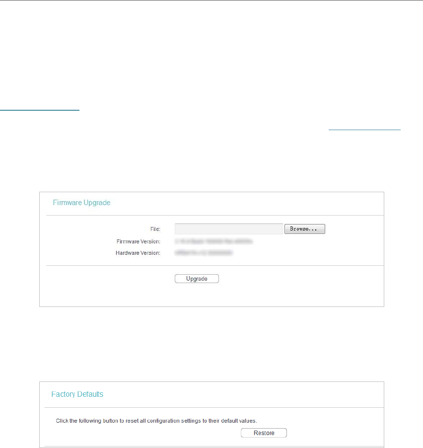
4. 5. 4. Firmware Upgrade
TP-LINK is dedicated to improving and richening the product features, giving users
a better network experience. We will release the latest firmware at TP-LINK official
website. You can download the latest firmware file from the Support page of our website
www.tp-link.com and upgrade the firmware to the latest version.
1. Download the latest firmware file for the access point from our website www.tp-link.com.
2. Visit
http://tplinkap.net, and log in using admin (all lowercase) for both Username and Password.
3. Go to System Tools > Firmware Upgrade.
4. Click Browse to locate the downloaded firmware file, and click Upgrade.
4. 5. 5. Factory Defaults
1. Visit http://tplinkap.net, and log in using admin (all lowercase) for both Username and Password.
2. Go to
System Tools > Factory Defaults. Click Restore to reset all settings to the default values.
• The default Username: admin
• The default
Password: admin
• The default
IP Address: 192.168.0.254
• The default
Subnet Mask: 255.255.255.0
4. 5. 6. Backup & Restore
The configuration settings are stored as a configuration file in the access point. You can
backup the configuration file in your computer for future use and restore the access
point to the previous settings from the backup file when needed.
1. Visit http://tplinkap.net, and log in using admin (all lowercase) for both Username and Password.
2. Go to System Tools > Backup & Restore.
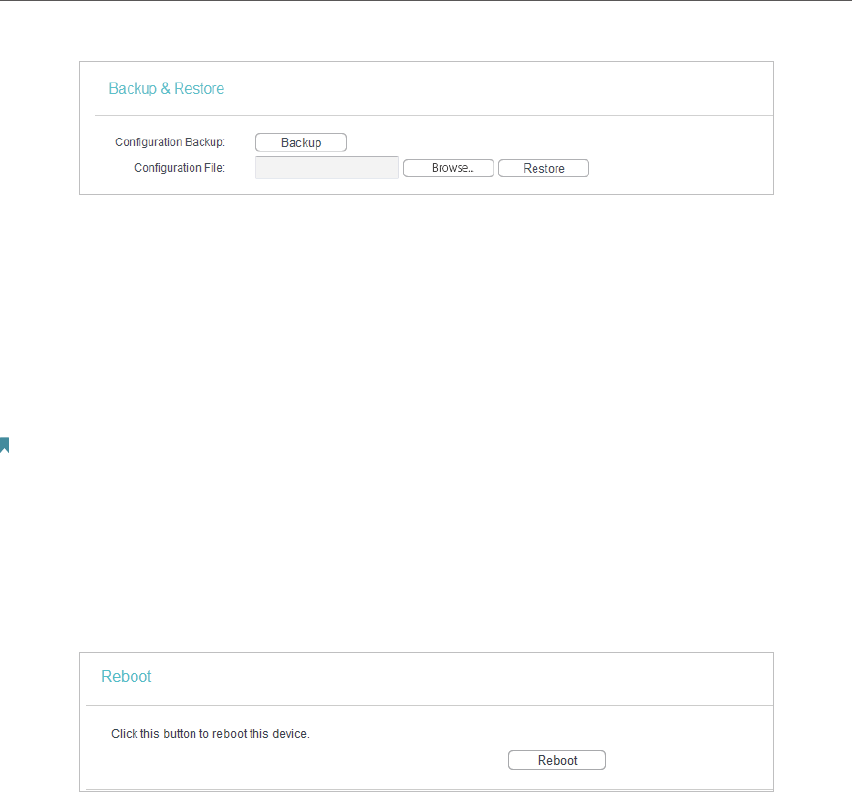
51
Chapter 4
• To backup configuration settings:
Click Backup to save a copy of the current settings in your local computer. A “.bin“ file
of the current settings will be stored in your computer.
• To restore configuration settings:
1. Click Choose File to locate the backup configuration file stored in your computer, and click
Restore.
2. Wait a few minutes for the restoring and rebooting.
Note:
During the restoring process, do not power off or reset the access point.
4. 5. 7. Reboot
1. Visit http://tplinkap.net, and log in using admin (all lowercase) for both Username and Password.
2. Go to System Tools > Reboot, and you can restart your access point.
Some settings of the access point will take effect only after rebooting, including:
• Change the LAN IP Address (system will reboot automatically).
• Change the DHCP Settings.
• Change the Working Modes.
• Change the Web Management Port.
• Upgrade the firmware of the access point (system will reboot automatically).
• Restore the access point to its factory defaults (system will reboot automatically).
• Update the configuration with the file (system will reboot automatically).
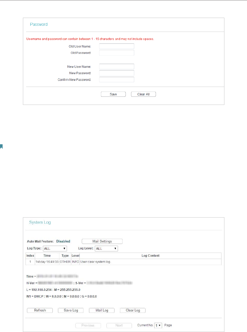
4. 5. 8. Password
1. Visit http://tplinkap.net, and log in using admin (all lowercase) for both Username and Password.
2. Go to System Tools > Password, and you can change the factory default username and
password of the access point.
52
Chapter 4
It is strongly recommended that you change the default username and password of
the access point, for all users that try to access the access point’s web-based utility or
Quick Setup will be prompted for the access point’s username and password.
Note:
The new username and password must not exceed 15 characters and not include any spacing.
3. Click Save.
4. 5. 9. System Log
1. Visit http://tplinkap.net, and log in using admin (all lowercase) for both Username and Password.
2. Go to System Tools > System Log, and you can view the logs of the access point.
• Auto Mail Feature - Indicates whether the auto mail feature is enabled or not.
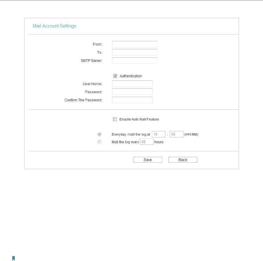
• Mail Settings - Set the receiving and sending mailbox address, server address,
validation information as well as the timetable for Auto Mail Feature.
53
Chapter 4
• From - Your mail box address. The access point will connect it to send logs.
• To - Recipient’s mail address. The destination mailbox which will receive logs.
• SMTP Server - Your smtp server. It corresponds with the mailbox filled in the
From field. You can log on the relevant website for help if you are not clear with
the address.
• Authentication - Most SMTP Server requires Authentication. It is required by
most mailboxes that need user name and password to log in.
Note:
Only when you select Authentication, do you have to enter the user name and password in the following fields.
• User Name - Your mail account name filled in the From field. The part behind @
is included.
• Password - Your mail account password.
• Confirm The Password - Enter the password again to confirm.
• Enable Auto Mail Feature - Select it to mail logs automatically. You could mail
the current logs either at a specified time everyday or by intervals, but only one
could be the current effective rule. Enter the desired time or intervals in the
corresponding field.
Click Save to apply your settings.
Click Back to return to the previous page.
• Log Type - By selecting the log type, only logs of this type will be shown.
• Log Level - By selecting the log level, only logs of this level will be shown.
• Refresh - Refresh the page to show the latest log list.

54
Chapter 4
• Save Log - Click to save all the logs in a txt file.
• Mail Log - Click to send an email of current logs manually according to the address
and validation information set in Mail Settings.
• Clear Log - All the logs will be deleted from the access point permanently, not just
from the page.
Click Next to go to the next page, or click Previous to return to the previous page.
4. 6. Logout
Click Logout at the bottom of the main menu, and you will log out of the web page and
return to the login window.

55
FAQ
Q1. How do I restore my Access Point’s configuration to its factory
default settings?
With the device powered on, use a pin to press and hold the Reset button until the Power
LED starts blinking, then release the button.
Note:
Upon resetting, all previous configurations will be cleared, and the AP device will reset to the default Access Point Mode.
Q2. What can I do if I forgot my wireless password?
The default wireless password is printed on the label of the access point. If the password
has been altered, please connect your computer to the access point using an Ethernet
cable and follow the steps below:
1. Visit http://tplinkap.net, and log in using admin (all lowercase) for both Username and Password.
2. Go to Wireless > Wireless Security to retrieve or reset your wireless password.
Q3. What can I do if I forgot my login password of the web management
page?
The default username and password of the web management page are admin (in
lowercase).
If you have altered the username and password but Password Recovery is disabled:
1. Reset the access point to factory default settings: use a pin to press and hold the Reset button
until the Power LED starts bliking, then release the button.
2. Visit
http://tplinkap.net, and log in using admin (all lowercase) for both Username and Password.
Note: You’ll need to reconfigure the access point to surf the Internet once the access point is reset, and please mark
down your new password for future use.
Q4. What can I do if my wireless is not stable?
It may be caused by too much interference, you can try the following methods:
• Set your wireless channel to a different one.
• Move the AP device to a new location away from Bluetooth devices and other
household electronics, such as cordless phone, microwave, and baby monitor and
more, to minimize signal interference.
Q5. What can I do to maximize my signal strength in Repeater/Bridge
mode?
When choosing an ideal location to optimize wireless signal in Repeater/ Bridge mode,
please use the following recommendations.
56
• The Best Way is Halfway
Generally, the ideal location for the repeater is about halfway between your wireless
router and your wireless clients and make sure that the location you choose is within
the range of the host router. If that is not possible, place it closer to your wireless
router to ensure stable performance.
• Less Obstacles Ensure Better Performance
Choose a location with less obstacles that may block the signal between the AP
device and the host network. An open corridor or a spacious location is ideal.
• Less Obstacles Ensure Better Performance
Choose a location with less obstacles that may block the signal between the AP
device and the host network. An open corridor or a spacious location is ideal.

57
COPYRIGHT & TRADEMARKS
Specifications are subject to change without notice. is a registered trademark of
TP-LINK TECHNOLOGIES CO., LTD. Other brands and product names are trademarks or
registered trademarks of their respective holders.
No part of the specifications may be reproduced in any form or by any means or used
to make any derivative such as translation, transformation, or adaptation without
permission from TP-LINK TECHNOLOGIES CO., LTD. Copyright © 2016 TP-LINK
TECHNOLOGIES CO., LTD. All rights reserved.

FCC STATEMENT
This equipment has been tested and found to comply with the limits for a Class B digital
device, pursuant to part 15 of the FCC Rules. These limits are designed to provide
reasonable protection against harmful interference in a residential installation. This
equipment generates, uses and can radiate radio frequency energy and, if not installed
and used in accordance with the instructions, may cause harmful interference to radio
communications. However, there is no guarantee that interference will not occur in a
particular installation. If this equipment does cause harmful interference to radio or
television reception, which can be determined by turning the equipment off and on, the
user is encouraged to try to correct the interference by one or more of the following
measures:
Reorient or relocate the receiving antenna.
Increase the separation between the equipment and receiver.
Connect the equipment into an outlet on a circuit different from that to which the
receiver is connected.
Consult the dealer or an experienced radio/ TV technician for help.
This device complies with part 15 of the FCC Rules. Operation is subject to the following
two conditions:
1This device may not cause harmful interference.
2This device must accept any interference received, including interference that may
cause undesired operation.
Any changes or modifications not expressly approved by the party responsible for
compliance could void the user’s authority to operate the equipment.
Note: The manufacturer is not responsible for any radio or TV interference caused by
unauthorized modifications to this equipment. Such modifications could void the user’s
authority to operate the equipment.
FCC RF Radiation Exposure Statement:
This equipment complies with FCC RF radiation exposure limits set forth for an
uncontrolled environment. This device and its antenna must not be co-located or
operating in conjunction with any other antenna or transmitter.
“To comply with FCC RF exposure compliance requirements, this grant is applicable to
only Mobile Configurations. The antennas used for this transmitter must be installed to
provide a separation distance of at least 20 cm from all persons and must not be
co-located or operating in conjunction with any other antenna or transmitter.”

CE Mark Warning
This is a class B product. In a domestic environment, this product may cause radio
interference, in which case the user may be required to take adequate measures.
RF Exposure Information
This device meets the EU requirements (1999/5/EC Article 3.1a) on the limitation of
exposure of the general public to electromagnetic fields by way of health protection.
The device complies with RF specifications when the device used at 20 cm from your
body.
Canadian Compliance Statement
This device complies with Industry Canada license-exempt RSSs. Operation is subject to
the following two conditions:
3This device may not cause interference, and
4This device must accept any interference, including interference that may cause
undesired operation of the device.
Le présent appareil est conforme aux CNR d’Industrie Canada applicables aux appareils
radio exempts de licence. L’exploitation est autorisée aux deux conditions suivantes :
5l’appareil ne doit pas produire de brouillage;
6l’utilisateur de l’appareil doit accepter tout brouillage radioélectrique subi, meme si le
brouillage est susceptible d’en compromettre le fonctionnement.
This radio transmitter (IC: 8853A-WA901NDV5/ Model: TL-WA901ND V5) has been
approved by Industry Canada to operate with the antenna types listed below with the
maximum permissible gain indicated. Antenna types not included in this list below, having
a gain greater than the maximum gain indicated for that type, are strictly prohibited for use
with this device.
Le présent émetteur radio (IC: 8853A-WA901NDV5/ Model: TL-WA901ND V5) a été
approuvé par Industrie Canada pour fonctionner avec les types d'antenne énumérés
ci-dessous et ayant un gain admissible maximal. Les types d'antenne non inclus dans
cette liste ci-dessous et dont le gain est supérieur au gain maximal indiqué, sont
strictement interdits pour l'exploitation de l'émetteur.
Radiation Exposure Statement:
This equipment complies with IC radiation exposure limits set forth for an uncontrolled
environment. This equipment should be installed and operated with minimum distance
20cm between the radiator & your body.

Déclaration d'exposition aux radiations:
Cet équipement est conforme aux limites d'exposition aux rayonnements IC établies pour
un environnement non contrôlé. Cet équipement doit être installé et utilisé avec un
minimum de 20 cm de distance entre la source de rayonnement et votre corps.
Industry Canada Statement
CAN ICES-3 (B)/NMB-3(B)
Korea Warning Statements
.
NCC Notice
!"#$!%&'()*+,-./012
34 '56*34789:*;<
= +,/0>?@ABCDEFGHIJKLEFKMN!
OPQR,!STUVWEFNX0YZ+,<[\G]!^]_`abWc
]< defG]*gb'hijDkl,8mEF<
BSMI Notice
BCnoDp\
q+,7rstOu*v;wxyz{|}s~+,yz{<
yz{[qsc<q+,'*H<
!q*yz{<
tG+,!jyz{}a$S¡¢£!q¤¥*¦§<
qyz{¨©ª«£s}¬X<"L®¯}G!°±/$©²³´µ¨¶<
q/·¸2¹º!/·»¼2H½¾yz{!q¿ÀÁ}ÂbÃÄHÅ\ga<
Продукт сертифіковано згідно с правилами системи УкрСЕПРО на відповідність
вимогам нормативних документів та вимогам, що передбачені чинними
законодавчими актами України.
Safety Information

When product has power button, the power button is one of the way to shut off the
product; when there is no power button, the only way to completely shut off power is
to disconnect the product or the power adapter from the power source.
Don’t disassemble the product, or make repairs yourself. You run the risk of electric
shock and voiding the limited warranty. If you need service, please contact us.
Avoid water and wet locations.
Adapter shall be installed near the equipment and shall be easily accessible. The
plug considered as disconnect device of adapter.
Use only power supplies which are provided by manufacturer and in the
original packing of this product. If you have any questions, please don't hesitate to
contact us.
Explanation of the symbols on the product label
Symbol
Explanation
DC voltage
RECYCLING
This product bears the selective sorting symbol for Waste electrical and electronic
equipment (WEEE). This means that this product must be handled pursuant to
European directive 2012/19/EU in order to be recycled or dismantled to minimize
its impact on the environment.
User has the choice to give his product to a competent recycling organization or to
the retailer when he buys a new electrical or electronic equipment.