TRAFICON N V 10-6034-6035 TrafiCam Wireless US User Manual Man TrafiCam R600 4TI R401 Installation EN
TRAFICON N.V. TrafiCam Wireless US Man TrafiCam R600 4TI R401 Installation EN
Contents
- 1. users manual
- 2. revised users manual
users manual
i
WX
TrafiCam® with a 4TI interface
Safety warning
EN55022
FCC Part 15
Warning
This is a class A product. In a domestic environment this product may cause radio interference in which
case the user may be required to take adequate measures.
This device complies with part 15 of the FCC Rules. Operation is subject to the following two
conditions: (1) This device may not cause harmful interference, and (2) this device must accept any
interference.
Note: This equipment has been tested and found to comply with the limits for a Class A digital device,
pursuant to part 15 of the FCC Rules. These limits are designed to provide reasonable protection
against harmful interference when the equipment is operated in a commercial environment. This
equipment generates, uses, and can radiate radio frequency energy and, if not installed and used in
accordance with the instruction manual, may cause harmful interference to radio communications.
Operation of this equipment in a residential area is likely to cause harmful interference in which case
the user will be required to correct the interference at his own expense.
Modifications not expressly approved by the manufacturer could void the user's authority to operate the
equipment under FCC rules.
draft version
draft version
ii
WX
TrafiCam® with a 4TI interface
Notice
The information contained in this document is subject to change without notice.
Traficon® n.v. makes no warranty of any kind with regard to this material, including, but not limited to,
the implied warranties of merchantability and fitness for a particular purpose.
Traficon® n.v. shall not be liable for errors contained herein or for incidental or consequential damages
in connection with the furnishing, performance, or use of this material.
No part of this document may be copied, reproduced, or translated to another language without the
prior written consent of Traficon® n.v.
© Copyright 2007, Traficon® n.v. - All rights reserved
Traficon® n.v.
Vlamingstraat 19
B-8560 Wevelgem
Belgium
Tel +32 (0)56 37.22.00
Fax +32 (0)56 37.21.96
E-mail traficon@traficon.com
draft version
draft version
iii
WX
TrafiCam® with a 4TI interface
Table of contents
Introduction . . . . . . . . . . . . . . . . . . . . . . . . . . . . . . . . . . . . . . . . . . . . . . . . . . . . . . . . . . . . . 1
Hardware. . . . . . . . . . . . . . . . . . . . . . . . . . . . . . . . . . . . . . . . . . . . . . . . . . . . . . . . . . . . . . . . 2
The TrafiCam® system items . . . . . . . . . . . . . . . . . . . . . . . . . . . . . . . . . . . . . . . . . . . . . . . 2
The TrafiCam® sensor . . . . . . . . . . . . . . . . . . . . . . . . . . . . . . . . . . . . . . . . . . . . . . . . . . . . 4
The 4TI interface . . . . . . . . . . . . . . . . . . . . . . . . . . . . . . . . . . . . . . . . . . . . . . . . . . . . . . . .6
The cables for connection . . . . . . . . . . . . . . . . . . . . . . . . . . . . . . . . . . . . . . . . . . . . . . . . . 8
The accessories for mounting . . . . . . . . . . . . . . . . . . . . . . . . . . . . . . . . . . . . . . . . . . . . . . 9
Installation . . . . . . . . . . . . . . . . . . . . . . . . . . . . . . . . . . . . . . . . . . . . . . . . . . . . . . . . . . . . . . 10
Maintenance . . . . . . . . . . . . . . . . . . . . . . . . . . . . . . . . . . . . . . . . . . . . . . . . . . . . . . . . . . . . . 14
Hardware specification - TrafiCam® sensor. . . . . . . . . . . . . . . . . . . . . . . . . . . . . . . . . . . . 15
Hardware specification - 4TI interface . . . . . . . . . . . . . . . . . . . . . . . . . . . . . . . . . . . . . . . . 16
Specification - wireless communication . . . . . . . . . . . . . . . . . . . . . . . . . . . . . . . . . . . . . . 17
Index . . . . . . . . . . . . . . . . . . . . . . . . . . . . . . . . . . . . . . . . . . . . . . . . . . . . . . . . . . . . . . . . . . . 18
draft version
draft version
iv
WX
TrafiCam® with a 4TI interface
List of figures
Figure 1: TrafiCam® installed at an intersection . . . . . . . . . . . . . . . . . . . . . . . . . . . . . . . . . . . 1
Figure 2: Items of the TrafiCam® system . . . . . . . . . . . . . . . . . . . . . . . . . . . . . . . . . . . . . . . . 2
Figure 3: Architecture of the TrafiCam® system . . . . . . . . . . . . . . . . . . . . . . . . . . . . . . . . . . . 3
Figure 4: Front and side view of the TrafiCam® sensor. . . . . . . . . . . . . . . . . . . . . . . . . . . . . . 4
Figure 5: The TrafiCam® sensor opened . . . . . . . . . . . . . . . . . . . . . . . . . . . . . . . . . . . . . . . . 5
Figure 6: The 4TI interface. . . . . . . . . . . . . . . . . . . . . . . . . . . . . . . . . . . . . . . . . . . . . . . . . . .6
Figure 7: The cables for connection. . . . . . . . . . . . . . . . . . . . . . . . . . . . . . . . . . . . . . . . . . . . 8
Figure 8: The mounting accessories (brackets and tube) . . . . . . . . . . . . . . . . . . . . . . . . . . . 9
draft version
draft version
1
WX
TrafiCam® with a 4TI interface
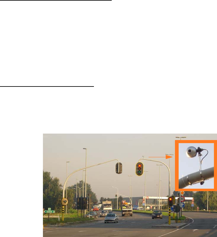
1. Introduction
This manual describes the hardware and installation of a wireless TrafiCam® system with the 4TI as
the interface between the TrafiCam® sensor, PC and traffic controller.
Functional characteristics of TrafiCam®
• Presence detection at the stop bar on intersections
• Advance detection of vehicles approaching the intersection
on up to 8 zones over different lanes.
The user can make these zones direction sensitive.
Via its digital outputs, TrafiCam® provides an input to the traffic controller upon presence detection.
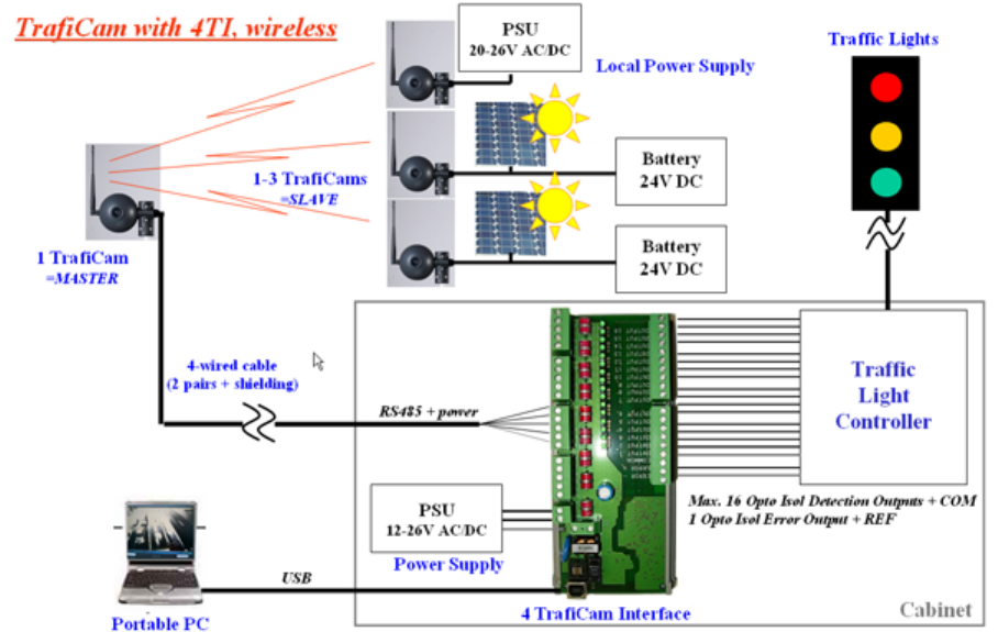
Functional characteristics of 4TI
• Serves as the interface for up to 4 TrafiCam® sensors
• Provides up to 16 outputs (maximum 4 per TrafiCam®) to the traffic controller
Figure 1: TrafiCam® installed at an intersection
The user configures TrafiCam® and the 4TI via TrafiCam® PC Tool. This tool allows to:
For TrafiCam®
• place the presence detection zones on an image from TrafiCam®
• assign the hardware outputs to the presence zones
• activate and verify the configuration
For 4TI
• link the outputs of TrafiCam® sensors and 4TI
• activate the system configuration
draft version
draft version
2
WX
TrafiCam® with a 4TI interface
2. Hardware
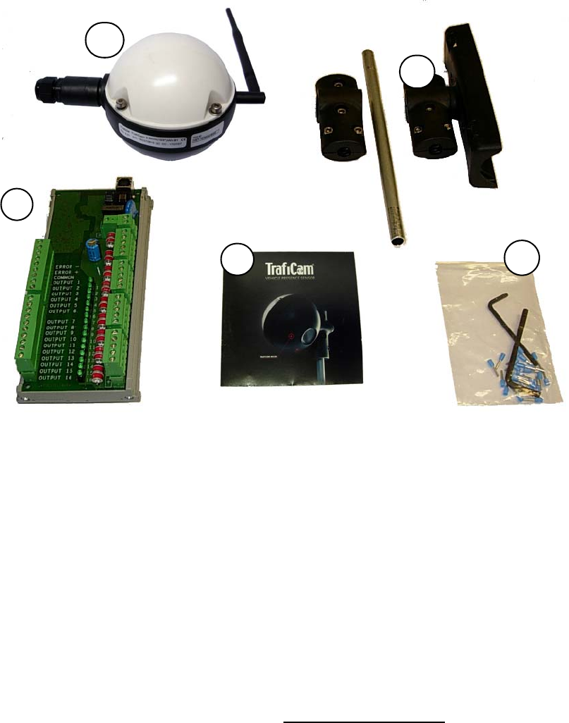
2.1. The TrafiCam® system items
The TrafiCam® system has the following items.
Figure 2: Items of the TrafiCam® system
1 = The TrafiCam® sensor
2 = The mounting accessories
3 = The installation CD (with the PC Tool and the manuals)
4 = Tools (hex keys and cable tags)
5 = The 4TI interface
In addition, the installation requires:
* retaining straps
* connection cables (see The cables for connection)
* PSU (12-26 V AC/DC)
Note: Traficon does not supply the retaining straps or the PSU.
1
5
2
34
draft version
draft version
4
WX
TrafiCam® with a 4TI interface
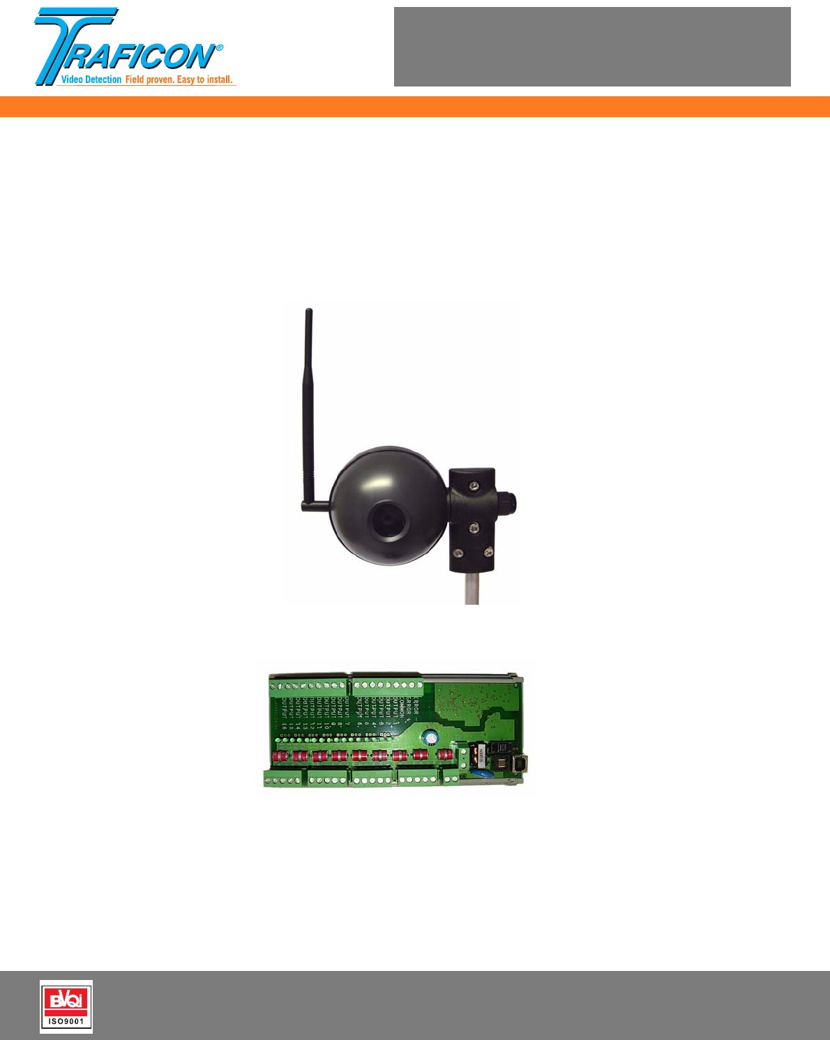
2.2. The TrafiCam® sensor
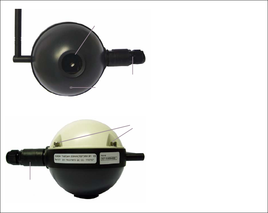
Figure 4: Front and side view of the TrafiCam® sensor
A = The lens
B = The gland to insert the cable for
connection between sensor and
interface
C = The LED (will light upon presence
detection)
D = The screws on the rear shell (to
open the sensor)
E = The rotating point to fix the
mounting bracket
A
C
D
E
B
draft version
draft version
5
WX
TrafiCam® with a 4TI interface
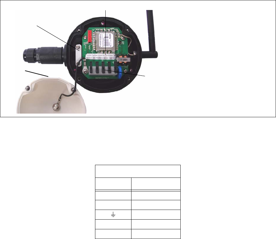
Figure 5: The TrafiCam® sensor opened
CN1 = The connector to the 4TI
CN1 pinout: see below.
A = The fixation plate (to keep the
connection cable in place)
B = The product label
C = Flattened side of the rear shell (as
an aid to close the sensor)
Pinout of connector CN1
Pin Description
+ + Power supply
- - Power supply
Grounding
A RS-485A
B RS-485B
CN1
A
C
B
draft version
draft version
6
WX
TrafiCam® with a 4TI interface
2.3. The 4TI interface
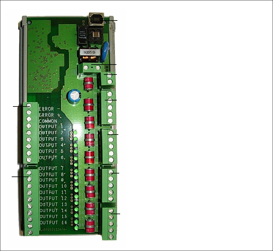
Figure 6: The 4TI interface
A
The USB/B connector (to connect to the PC)
JP12
The grounding
J11
The PSU connector for power supply to the
4TI interface
4TI can also feed the TrafiCam® sensors.
J1, J3, J4 or J5
The connector to the TrafiCam® master sensor
J12, J13
The output connectors to the traffic controller
The tables below provide the pinout scheme
of connector J1 to J5, J12 and J13.
JP12
A
J11
J5
J4
J3
J1
J12
J13
draft version
draft version

7
WX
TrafiCam® with a 4TI interface
Pinout of connector J1
(same for connector J3, J4, J5)
Pin Description
+ + Power supply
- - Power supply
A RS-485A
B RS-485B
Grounding
Pinout of connector J12 and J13
Pin Description
Error - - Error output
Error + + Error output
Common Common output
(for output 1 to 16)
Output 1 to 16 Output 1 to 16
draft version
draft version
8
WX
TrafiCam® with a 4TI interface
2.4. The cables for connection
The table below gives an overview of the cables used for connecting the TrafiCam® sensor, the 4TI
interface and the PC.
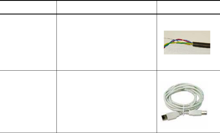
Figure 7: The cables for connection
Connection Cable Illustration
Sensor to interface Shielded twisted pair cable, UV-resistant,
4 wires + shielding
STP, d. 5-10 mm, min 2x2 + shield
Interface to PC USB cable type USB/A - USB/B
draft version
draft version
9
WX
TrafiCam® with a 4TI interface
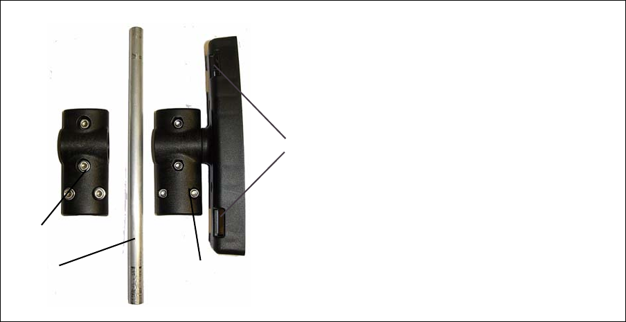
2.5. The accessories for mounting
There is a mounting bracket for the TrafiCam® sensor and a mounting bracket to the pole.
The tube connects both brackets.
Figure 8: The mounting accessories (brackets and tube)
A = The mounting bracket for the TrafiCam®
sensor
B = The tube
C = The mounting bracket to the pole
D = The holes to put the retaining straps
through
C
A
B
D
draft version
draft version
10
WX
TrafiCam® with a 4TI interface
3. Installation
Do not remove the lens cover until the TrafiCam® is installed.
Ensure that the system power is off before starting the installation.
.
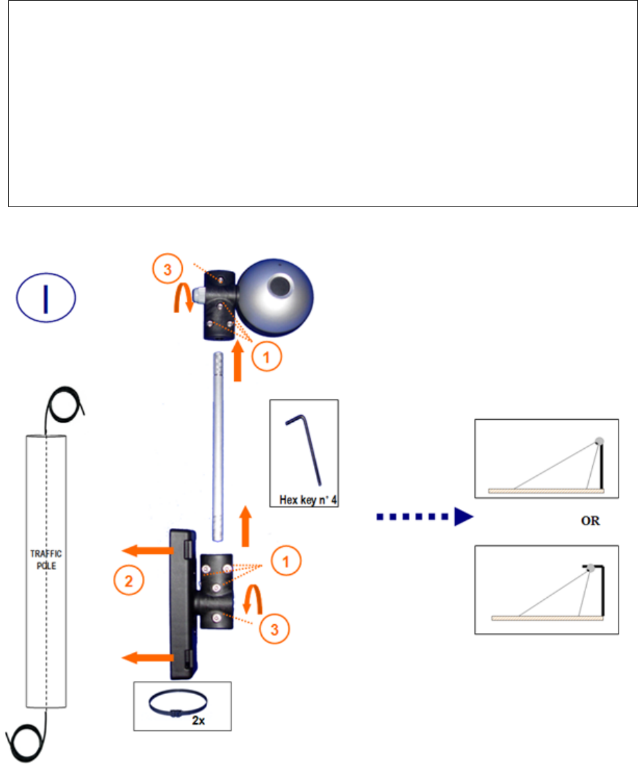
Step I: Mount the TrafiCam® on a stable pole.
1. Fix the mounting tube to the brackets (Torque max = 1,3 Nm).
2. Fix the TrafiCam® to the pole using retaining straps.
Put the retaining straps through the holes in the bracket.
3. Position the TrafiCam® provisionally (Torque max = 1,3 Nm).
You can mount the TrafiCam® in a horizontal or vertical position.
TrafiCam® is a downward looking device.
Verify that there is no horizon in the image!
draft version
draft version

11
WX
TrafiCam® with a 4TI interface
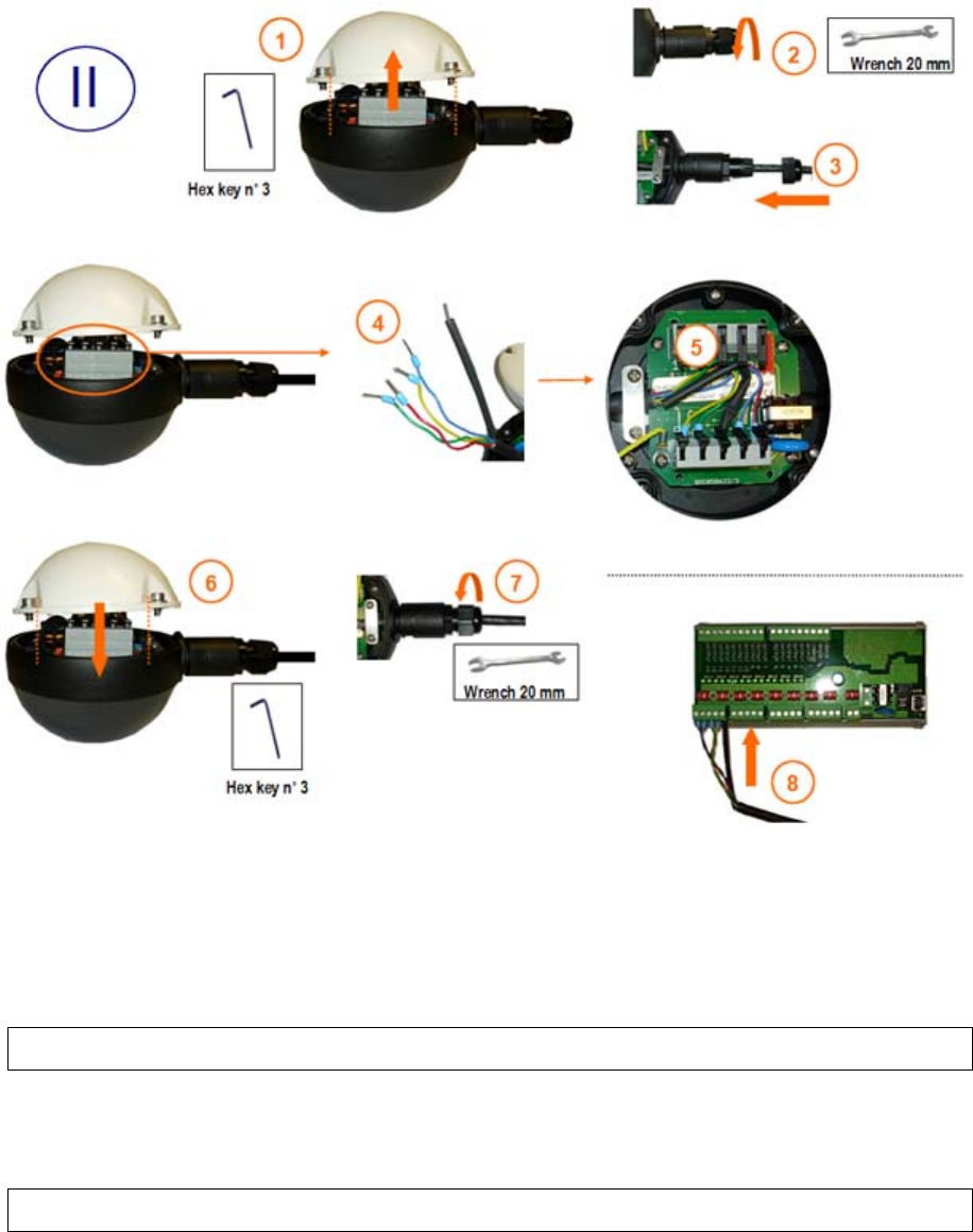
Step IIa: Connect the TrafiCam® master sensor to the 4TI interface.
Use a shielded twisted pair cable, UV-resistant, 4 wires+shield.
At the Traficam® side
1. Open the sensor.
2. Loosen the cable gland.
3. Insert the cable into TrafiCam® through the gland.
4. Strip the wires and fix the cable tags. Isolate the grounding wire.
5. connect the cable to CN1 and fix the cable plate.
6. Close the TrafiCam® (Torque max = 1,0 Nm).
7. Tighten the cable gland.
At the 4TI interface side
8. Connect the cable to the connector J1 (or J3, J4, J5).
Step IIb: Connect the TrafiCam® slave sensors to the local power supply.
Use a shielded twisted pair cable, UV-resistant, 2 wires +grounding.
At the Traficam® side
1. Open the sensor.
2. Loosen the cable gland.
3. Insert the cable into TrafiCam® through the gland.
4. Strip the wires and fix the cable tags. Isolate the grounding wire.
5. connect the cable to CN1 (power supply and grounding pins only) and fix the cable plate.
6. Close the TrafiCam® (Torque max = 1,0 Nm).
7. Tighten the cable gland.
At the 4TI interface side
No connections
Note: If you wish to supply power to the slave sensors via the 4TI interface you should connect
only the pins of CN1 as described above. Do NOT connect the RS-485 wires.
draft version
draft version
13
WX
TrafiCam® with a 4TI interface
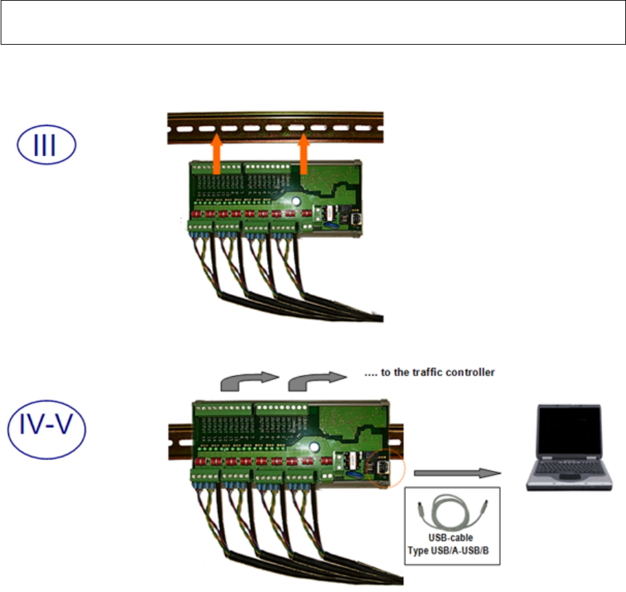
Finally connect the power supply.
The configuration manual (separate manual) describes how to optimise the position of the
TrafiCam®.
Tighten all screws after optimising the position of the TrafiCam®.
Step V: Connect the interface to the PC.
Use a USB cable type USB/A - USB/B.
draft version
draft version

14
WX
TrafiCam® with a 4TI interface
4. Maintenance
The maintenance of the TrafiCam® can be done during the regular maintenance of the traffic lights and
controller.
Note: Depending on the on-site conditions, you may need to increase the frequency of maintenance.
Instruction Frequency Tools Remark
Clean the faceplate of the
TrafiCam®.
Check the camera image.
Verify the configuration of
the system.
Once per year
Once per year
Soft cloth and mild
detergent
PC with TrafiCam® PC
tool
Avoid movement of the
TrafiCam®.
Use the configuration manual
for guidance.
draft version
draft version

15
WX
TrafiCam® with a 4TI interface
5. Hardware specification - TrafiCam® sensor
CAMERA
CMOS, black&white, resolution 640x480, 1/3 “
DIMENSIONS
L x H x W: 45 cm x 16 cm x 10 cm mounted vertically
41 cm x 18 cm x 10 cm mounted horizontally
Mass (including mounting bracket, excluding cable): 600 g
Sensor diameter: 10 cm
MATERIALS
Sensor
Front and back shell: polycarbonate
Mid section: fibre reinforced polyamide
Mounting bracket: fibre reinforced polyamide
Tube: aluminium
COMMUNICATION
RS485 service port for configuration
OUTPUTS
4 optically isolated digital outputs, Imax = 50 mA, Pmax = 300 mW
POWER SUPPLY VOLTAGE INPUT
+20V ...+26V AC/DC
POWER CONSUMPTION
85 mA @ +12 V DC (1,2 W)
50 mA @ +24 V DC (1,2 W)
ENVIRONMENTAL
Temperature range: between - 34°C and +80°C
0 to 95 % relative humidity, non-condensing
Housing: waterproof to IP67
Materials: weatherproof, UV-resistant
REGULATORY
EMC: CE Directive 89/336/EEC; product standard EN 55022 Class A
FCC: FCC part 15 Class A
NEMA: NEMA II Shock and vibration
LENS TYPE > Wide angle Narrow angle
Focal distance 3,0 mm 8,0 mm
Field of view - horizontal 95° 32°
Field of view - vertical 65° 22°
Field of view - diagonal 103° 39°
draft version
draft version
16
WX
TrafiCam® with a 4TI interface
6. Hardware specification - 4TI interface
DIMENSIONS
L x H x W: 18,5 cm x 8,5 cm x 5 cm; DIN-rail clickable
Mass: 250 g
COMMUNICATION
USB between 4TI and PC
RS-485 between 4TI and TrafiCam®
OUTPUTS
16 optically isolated digital outputs
1 optically isolated digital error output
POWER SUPPLY VOLTAGE INPUT
+12V ...+26V AC / DC
POWER CONSUMPTION
120 mA @ +12 V DC (1,5 W)
60 mA @ +24 V DC (1,5 W)
ENVIRONMENTAL
Temperature range: between - 34°C and +80°C
REGULATORY
EMC: CE Directive 89/336/EEC; product standard EN 55022 Class A
FCC: FCC part 15 Class A
NEMA: NEMA II Shock and vibration
draft version
draft version
17
WX
TrafiCam® with a 4TI interface
7. Specification - wireless communication
Wireless 915MHz Frequency Band (USA, Mexico, …)
Technology: Frequency Hopping Spread Spectrum (FHSS)
Frequency Range: 902-928MHz
Available Hop Patterns: 6
Transmission power (ERP): 250mW
Max. communications distance: max. 400m* with omni-directional antenna (to be confirmed)
Effective bandwidth: 115,2kbaud netto*
Input Voltage: 20-26V AC/DC
Current Consumption: 85mA @ 24V
Power Consumption: Peak 2,0W (to be confirmed), Average 1,5W (to be confirmed)
Certification:
FCC chapter 47 part 15
.207/209/249
FCC equipment autorisation: pending
FCC ID: VE7-10-6034-6035
* In ideal conditions: direct line of sight, no fixed objects in ellipse (trees/leafs, power lines, buildings,
etc..), no moving objects in ellipse (buses, trucks, trams, etc..), good weather, normal traffic
environment, no interference, 25mW transmission power, higher than 6m above the ground's surface
draft version
draft version
TrafiCam® with a 4TI interface
18
WX
Index
C
Connector pinout
4TI connector J1 (J3, J4, J5) 7
4TI connector J12 (J13) 7
TrafiCam connector CN1 5
H
Hardware specification
4TI interface 16
TrafiCam sensor 15
I
Installation accessories
cables for connection 8
mounting brackets and tube 9
Installation, stepwise 10
M
Maintenance 14
S
Specification wireless communication 17
System TrafiCam - 4TI
architecture 3
Items 2
T
TrafiCam sensor
front and side view 4
opened 5
draft version
draft version