TRAFICON N V 10-6034-6035 TrafiCam Wireless US User Manual Man TrafiCam R600 4TI R401 Installation EN
TRAFICON N.V. TrafiCam Wireless US Man TrafiCam R600 4TI R401 Installation EN
UserManual.wiki
>
TRAFICON N V
>
10-6034-6035 User Manual
>
users manual
Contents
1.
users manual
2.
revised users manual
users manual
Navigation menu
Upload a User Manual
Namespaces
Wiki Guide
HTML
PDF
Info
Views
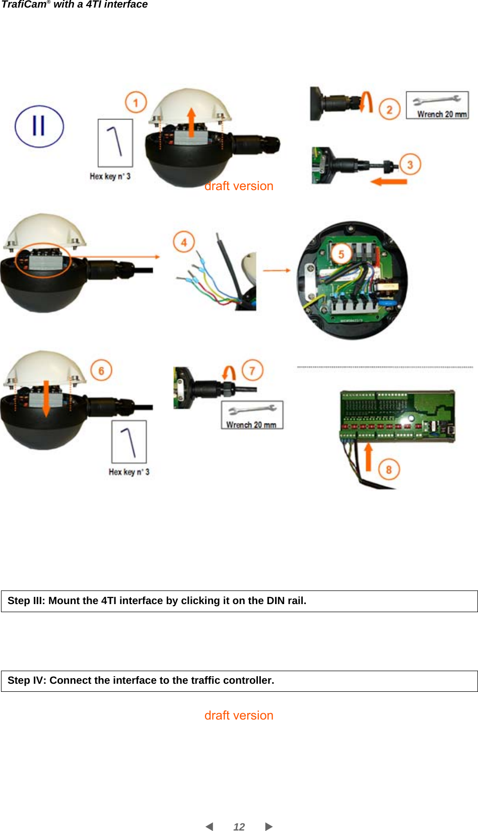
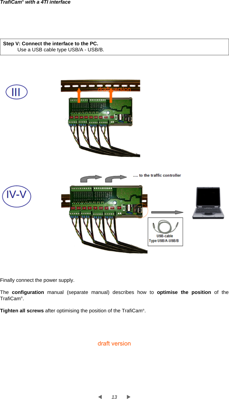
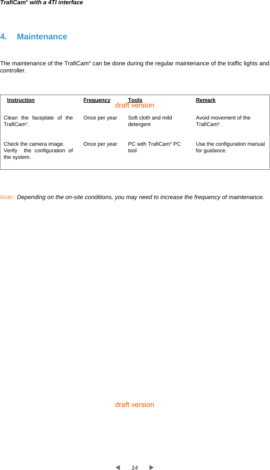
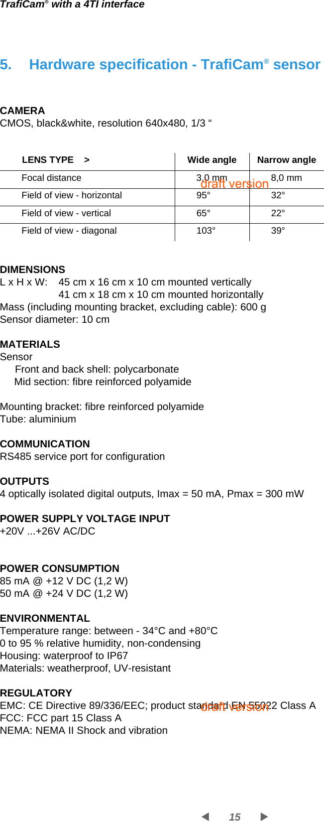
User Manual
Discussion / Help
Navigation