TRANE Air Conditioner/heat Pump(outside Unit) Manual L0801712
User Manual: TRANE TRANE Air conditioner/heat pump(outside unit) Manual TRANE Air conditioner/heat pump(outside unit) Owner's Manual, TRANE Air conditioner/heat pump(outside unit) installation guides
Open the PDF directly: View PDF ![]() .
.
Page Count: 8

TTB-IN-4A
18-A030 D10-2
Condensing Un
TTB012-024C
ALL phases of this installation must comply with NATIONAL, STATE AND LOCAL CODES
IMPORTANT -- This Document is customer property and is to remain with this unit. Please return to service
infbrmation pack upon completion of work.
These instructions do not cover all variations in
systems nor provide for every possible contingency
to be met in connection with installation. All phases
of this installation must comply with NATIONAL,
STATE AND LOCAL CODES. Should further informa-
tion be desired or should particular problems arise which
are not covered sufticiently for the purchaser's purposes,
the matter should be referred to your installing dealer or
local distributor.
A. GENERAL
The following instructions cover TTB012-024C; Condens-
ing Units.
NOTICE:
These outdoor units may be used with indoor units
equipped with Thermostatic Expansion Valve or
Accutron TMFlow Control Check Valve (F.C.C.V,) assem-
bly for refrigerant flow control only,
Check for transportation damage after unit is uncrated.
Report promptly, to the carrier, any damage fbund to the
unit.
To determine the electrical power requirements of the
unit, refer to the nameplate of the unit. The electrical
power available must agree with that listed on the
nameplate.
B. LOCATION &PREPARATION
OF THE UNIT
1. The trait should be set on a level support pad at least
as large as the unit base pan, such as a concrete slab.
If this is not the application used please refer to
application bulletin "Trane APB2001-02".
2. The support pad must NOT be in direct contact with
any structure. Unit must be positioned a minimum of
12" fi_om any wall or surrounding shrubbery to insure
adequate airflow. Clearance must be provided in front
of control box (access panels) & any other side requir-
ing service access to meet National Electrical (?ode.
Also, the unit location must be far enough away from
any structure to prevent excess roofrun-offwater from
pouring directly on the unit. Do not locate unit(s) close
to bedrooln(S).
@5 FT. ABOVE UNIT-UNRESTRICTED
3. The top discharge area must be unrestricted fi)r at
least five (5) feet above the unit.
4. When the outdoor unit is mounted on a roof, be sure
the roof will support the unit's weight. Properly
selected isolation is recommended to prevent sound or
vibration transmission to the building structure.
5. The maximum length ofrefi'igerant lines f?om outdoor
to indoor unit should NOT exceed eighty (80) feet.
6. If outdoor unit is mounted above the air handler,
maxfinmn lil_ should not exceed eighty (80) feet (suc-
tion line). Fair handler is mounted above condensing
unit, maximum lif_ should not exceed sixty (60) feet
(liquid line).
NOTE:
Refer to "Refrigerant Piping Software" Pub. No, 32-3312-02.

|nstaller's Guide
7. Locate and install indoor coil or air handler in accor-
dance with instruction included with that unit.
C. ACCUTRON TM FLOW CONTROL VALVE
If the indoor unit System Refl'igerant Flow control is an
Accutron TM orifice and check valve assembly, an orifice
size change may be necessary. See Figure 2.
The outdoor model determines the required orifice size.
Check the listed orifice size on nameplate of the selected
outdoor model. If the indoor unit is factory shipped with a
different orifice size, the orifice nmst be changed to obtain
system rated performance.
iMPORTANT:
The outdoor unit is shipped with the proper size orifice and a
stick-on orifice size label in an envelope attached to the
outdoor unit. Outdoor unit nameplate will have correct orifice
size specified as BAYFCCV---A for rated performance.
D. INSTALLING REFRIGERANT LINES
if using existing refrigerant lines make certain that all
joints are brazed, not soldered.
Condensing units have provisions for braze connections.
Pressure taps are provided on the service valves of outdoor
unit fbr compressor suction and liquid pressures.
The indoor end of the recommended refl'igerant line sets
may be straight or with a 90 degree bend, depending upon
situation requirements. This should be thoroughly
checked out before ordering refl'igerant line sets.
The gas line nmst always be insulated.
in scroll compressor applications, dome temperatures
may be hot. Do not touch top of compressor, may cause
minor to severe burning.
The units are factory charged with the system charge
required when using fil_een (15) feet of connecting line.
Unit nameplate charge is the same.
Final refrigerant charge adjustment is necessary.
Use the Charging Charts in the outdoor unit Service Facts.
1. Determine the most practical way to run the lines.
2. Consider types of bends to be made and space limitations.
NOTE:
Large diameter tubing will be very difficult to rebend
once it has been shaped,
3. Determine the best starting point lbr routing the
refl'igerant tubing- -INSIDE OR OUTSIDE THE
STRUCTURE.
4. Provide a pull-thru hole of sufficient size to allow both
liquid and gas lines.
5. Be sure the tubing is of sufficient length.
6. Uncoil the tubing -- do not Mnk or dent.
7. Route the tubing making all required bends and
properly secure the tubing bel[bre making connections.
8. To prevent a noise within the building structure due
to vibration transmission from the refrigerant lines,
the fbllowing precautions should be taken:
a. When the refrigerant lines have to be fastened to
floor joists or other l?aming in a structure, use
isolation type hangers.
b. Isolation hangers should also be used when reS"ig-
erant lines are run in stud spaces or enclosed
ceilings.
c. Where the refl'igerant lines run through a wall or
sill, they should be insulated and isolated.
d. Isolate the lines fl'om all ductwork.
E. SERVICE VALVE OPERATION
BRASS LiQUiD AND GAS LiNE SERVICE VALVES
The Brass Liquid and Gas Line Service Valves are lactory
shipped in the seated position to hold factory charge. The
pressure tap service port (when depressed) opens only to
the field brazing side of the valve when the valve is in the
seated position. The liquid line valve is not a back seating
valve (see WARNING below).
Extreme caution should be exercised when opening the
Liquid Line Service Valve. Turn valve stem counterclock-
wise only until the stem contacts the relied edge. (See
Figure 4) No torque is required.
@BRAZE TYPE iNDOOR END
ACCUTRON TM
COMPONENTS
SEALING CAP
_FLOW CONTROL
CHECK VALVE
(F,C.C.V,) ORIFICE
BO ss
_} FIELD SUPPLIED
LIQUID LINE
© 2003 American Standard Inc. All Rights Reserved 18-AC30D10-2

|nstaller's Guide
@LiQUiD LiNE SERVICE VALVE
UNIT SIDE OF
SERVICE VALVE
RETAINING RING
CAF
RETAINING RING
CAP
HEXHEADED
VALVE SYSTEM
LIQUID LINE
CONNECTION HEX HEADED
VALVE SYSTEM
GASLINE
CONNECTION
BRAZING REFRIGERANT LINES
1. Befbre brazing, remove plugs fl'om external copper
stub tubes. Clean internal and external surfaces of
stub tubes prior to brazing.
2. Cut and fit tubing, minimizing the use of sharp
90 ° bends.
3. Insulate the entire gas line and its fittings.
4. Do NOT allow uninsulated liquid line to come in
direct contact with bare gas line.
5. Precautions should be taken to avoid heat
damage to the pressure tap valve core during
brazing. It is recommended that the pressure
tap port valve core be removed and a wet rag
wrapped around the valve body.
NOTICE:
Use care to make sure that no moisture enters pressure
tap port, while wet rag is being used.
NOTICE:
Precautions should be taken to avoid heat damage to
basepan during brazing. It is recommended to keep the
flame directly off of the basepan.
6. Use a Dry Nitrogen Purge and Brazing Alloy without
flux when brazing the field line to the copper factory
connection. Flow dry nitrogen into either valve
pressure tap port, thru the tubing and out the other
port while brazing.
7. Braze using accepted good brazing techniques.
8. Leave heat shield in place while brazing to prevent
damaging the paint finish with torch. See Figure 4.
Discard the heat shield when finished with brazing.
LEAK CHECK
IMPORTANT:
Replace pressure tap port valve core before attaching hoses
for evacuation.
After the brazing operation of refi'igerant lines to both the
outdoor and indoor unit is completed, the field brazed
connections nmst be checked for leaks. Pressurize through
the service valve ports, the indoor unit and field refl'iger-
ant lines with dry nitrogen to 350-400 psi. Use soap
bubbles or other leak-checking methods to see that all field
joints are leak-fl'ee! If not, release pressure; then repair!
HEAT SHIELD
18-AC30D10-2 3
|.staller's Guide
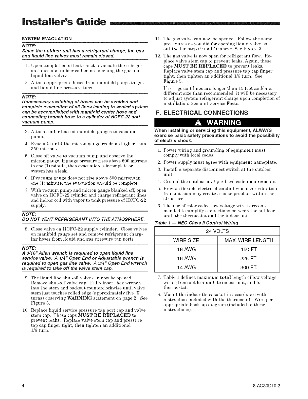
SYSTEM EVACUATION 11.
NOTE:
Since the outdoor unit has a refrigerant charge, the gas
and liquid line valves must remain closed, 12.
1. Upon completion of leak check, evacuate the refi'iger-
ant lines and indoor coil before opening the gas and
liquid line valves.
2. Attach appropriate hoses from manifold gauge to gas
and liquid line pressure taps.
NOTE:
Unnecessary switching of hoses can be avoided and
complete evacuation of al! lines leading to sealed system
can be accomplished with manifold center hose and
connecting branch hose to a cylinder of HCFC-22 and
vacuum pump,
3. Attach center hose of manifold gauges to vacuum
pump.
4. Evacuate until the micron gauge reads no higher than
350 microns.
5. Close offvalve to vacuum pump and observe the
micron gauge. If gauge pressure rises above 500 microns
in one (1) minute, then evacuation is incomplete or
system has a leak.
6. If vacuum gauge does not rise above 500 microns in
one (1) minute, the evacuation should be complete.
7. With vacuum pump and micron gauge blanked oft; open
valve on HCFC-22 cylinder and charge refl'igerant lines
and indoor coil with vapor to tank pressure of HCFC-22
supply.
NOTE:
DO NOT VENT REFRIGERANT INTO THE ATMOSPHERE.
8. (?lose valve on HCFC-22 supply cylinder. Close valves
on manifold gauge set and remove refl'igerant charg-
ing hoses from liquid and gas pressure tap ports.
NOTE:
A 3/16" Allen wrench is required to open liquid line
service valve. A 1/4" Open End or Adjustable wrench is
required to open gas line valve. A 3/4" Open End wrench
is required to take off the valve stem cap.
9. The liquid line shut-offvalve can now be opened.
Remove shut-off valve cap. Fully insert hex wrench
into the stem and backout counterclockwise until valve
stem just touches rolled edge (approximately five [5]
turns) observing WARNING statement on page 2. See
Figure 3.
10. Replace liquid service pressure tap port cap and valve
stem cap. These caps MUST BE REPLACED to
prevent leaks. Replace valve stem cap and pressure
tap cap finger tight, then tighten an additional
1/6 turn.
The gas valve can now be opened. Follow the same
procedures as you did for opening liquid valve as
outlined in steps 9 and 10 above. See Figure 3.
The gas valve is now open for refl'igerant flow. Re-
place valve stem cap to prevent leaks. Again, these
caps MUST BE REPLACED to prevent leaks.
Replace valve stem cap and pressure tap cap finger
tight, then tighten an additional 1/6 turn. See
Figure 5.
Ifrefi'igerant lines are longer than 15 feet and!or a
different size than recommended, it will be necessary
to adjust system refrigerant charge upon completion of
installation. See unit Service Facts.
F. ELECTRICAL CONNECTIONS
When installing or servicing this equipment, ALWAYS
exercise basic safety precautions to avoid the possibility
of electric shock.
1. Power wiring and grounding of equipment must
comply with local codes.
2. Power supply must agree with equipment nameplate.
3. Install a separate disconnect switch at the outdoor
unit.
4.
5.
Ground the outdoor unit per local code requirements.
Provide flexible electrical conduit whenever vibration
transmission may create a noise problem within the
structure.
6. The use of color coded low voltage wire is recom-
mended to simplify connections between the outdoor
unit, the thermostat and the indoor unit.
Table 1-- NEC Class It Control Wiring
24 VOLTS
WIRE SIZE MAX. WIRE LENGTH
18 AWG 150 FT
16 AWG 225 FT.
14 AWG 300 FT.
7. Table 1 defines maximmn total length of low voltage
wiring l}om outdoor unit, to indoor unit, and to
thermostat.
8. Mount the indoor thermostat in accordance with
instruction included with the thermostat. Wire per
appropriate hook-up diagram (included in these
instructions).
4 18-AC30D10-2
|nstaRer's Guide
G. COMPRESSOR START UP
After all electrical wiring is complete, SET THE THER-
MOSTAT SYSTEM SWITCH IN THE OFF POSITION SO
COMPRESSOR WILL NOT RUN, and apply power by
closing the system main disconnect switch. This will
activate the compressor sump heat (where used). Do not
change the Thermostat System Switch until power has
been applied for one (1) hour. Following this procedure will
prevent potential compressor overload trip at the initial
start-up.
H. OPERATIONAL AND
CHECKOUT PROCEDURES
Final phases of this installation are the unit Operational
and Checkout Procedures which are fbund in this instruc-
tion (see page 8). To obtain proper perlbrmance, all units
must be operated and charge adjustments made in accor-
dance with procedures found in the Service Facts.
I. ELECTRIC HEATERS
Electric heaters, if used, are to be installed in the air
handling device according to the instructions accompany-
ing the air handler and the heaters.
J. START CONTROL
Provisions are made on these units for field installed start
kit accessory BAY41X228. When adding an accessory,
follow the instructions provided with the kit.
K. OUTDOOR THERMOSTAT
An outdoor thermostat TAYSTAT250B may be field
installed. For data, see wiring diagram attached to unit
and instruction sheet packaged with outdoor thermostat.
L. SEACOAST SHIELD
BAYSEAC001 (Seacoast Kit) is available for application on
units installed within one mile of salt water, including
seacoasts and inland waterways.
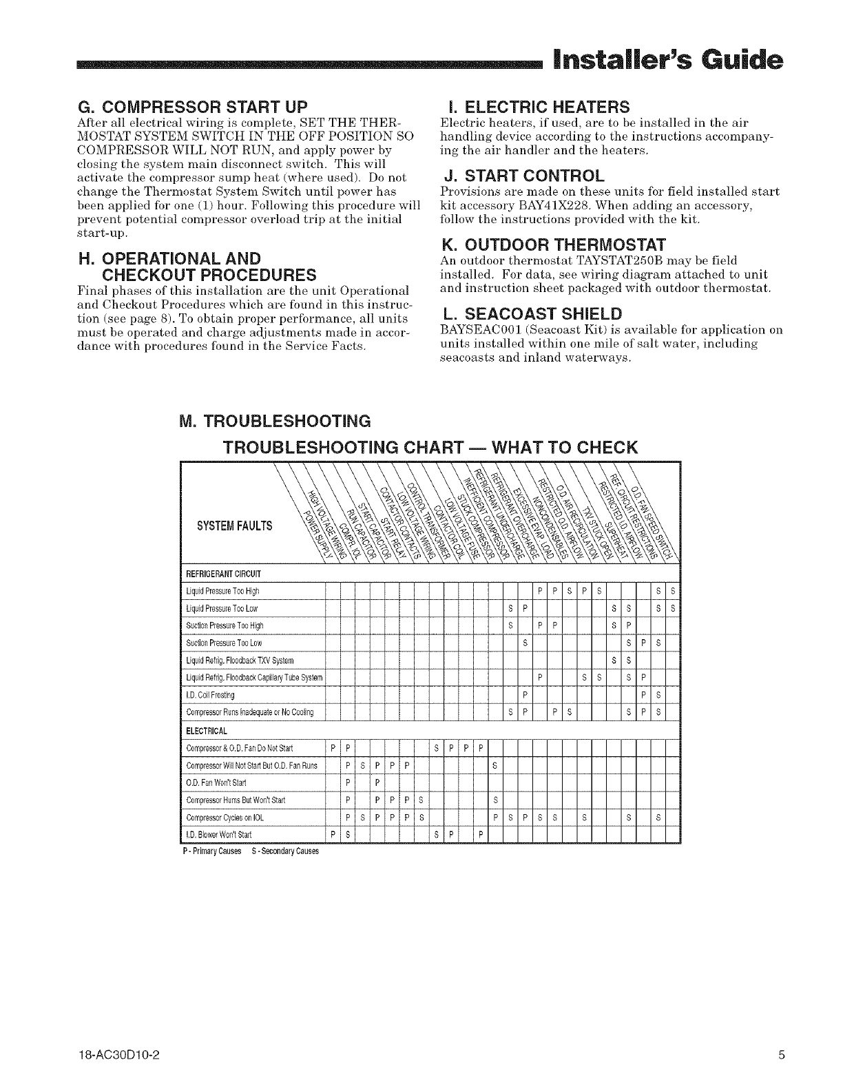
M. TROUBLESHOOTING
TROUBLESHOOTING CHART -- WHAT TO CHECK
SYSTEMFAULTS
REFRIGERANTCIRCUIT
LiquidPmsau_sToeHigh P P S P S S S
LiquidPressureToeLow S P S S S S
S P P S P
SuctionPressureTooHigh
SuctionPressureToo Low S S P S
LiquidRefdg.FlsadbaakTXV System S S
P S S S P
LiquidRefdg.FlssdbaskCapillaryTube System
i i
I.D.Coil Frosting P P S
S P P S S P S
CompressorRunsinadequatem No Cooling
!
I
i ELECTRICAL
Compressor&O.D.FanDaNstStad P P S P P P
CompressorWill NotStartBut O.D.Fan Runs P S P P P S
O.D.FanWon'tStart P P
CompresaorHumsButWoe'tStart P P P P S S
CompressorCydeson IOL P S P P P S P S P S S S S S
I.D. BblverWon'tStad P S S P P
P- Primary Causes S-SecondaryCauses
18-AC30D10-2 5

|.staller's Guide
TYPICAL FIELD HOOK-UP DIAGRAMS
' S]A IR I ANI)I kl_
R
£ G
W2
i .... W3
p,
PRINTED FROM B152901 P02
AI CONDI I ION}
...... y
ODT
_ ...... D
T'STAT
I STAGE
OR
2SILAGE
FURNACE AIR CONDITIONER
..... y
NOTE
...... B
PRINTEDFROM B152903P02
•kW2 presentonly on 2 stage
thermostatand furnace
Notes:
1. Be sure power supply agrees with equipment nameplate.
2. Power wiring and grounding of equipment must comply with local codes.
3. Low voltage wiring to be No. 18 AWG minimum conductor.
4. ©DT-B must be set lower than ©DT-A.
5. If outdoor thermostats (ODT) are not used connect W1 to W2 and W3.
LEGEND
..... FACTORY WIRING
_ FIELD WIRING
6 18-AC30D10-2

|nstaller's Guide
TTB012=024C OUTLINE DRAWING
Note: All dimensions are in MM (Inches).
595
\\
\
\
\\\22,2 I_) HOE FOR POWER W!RING
22.2 ¢_ ] HOLE WIT! RUBBER
oGROMMET FOR EONTRO
W[R] O
REAR VIEW
MODEL A B
TTB012C 5/8 1/4
TTB018C 5/8 1/4
TTB024C 3/4 5/16
NOTE: TABLE IN INCHES ONLY.
ELECTRICAL
CONTROLACCESS
(THIS SIDEONLY
FRONT
From Dwg. D147830 Rev. 2
18-AC30D10-2 7

|.staller's Guide
CHECKOUT PROCEDURE
After installation has been completed, it is recommended that the entire system be checked against the following list:
1. Refl'igerant Line, Leak checked ................................ [ ] 8. Supply registers and return grilles open and
2. Suction Lines and Fittings properly insulated ........ [ ]
3. Have all Refrigerant Lines been secured and
isolated properly? ....................................................... [ ]
4. Have passages through masonry been sealed?
If mortar is used, prevent mortar fl'om coming
into direct contact with copper tubing ..................... [ ]
5. Verify tightness of all electrical connects ................ [ ]
6. Observe outdoor fan during on cycle fbr clearance
and smooth operation ................................................ [ ]
7. Indoor coil drain line drains fl'eely. Pour water
into drain pan ............................................................. [ ]
unobstructed ............................................................... [
9. Return air filter installed .......................................... [
10. Thermostat thermometer is accurate. Check
against a reliable thermometer. Adjust per
instructions with thermostat .................................... [
11. Is correct speed tap being used?
(Indoor blower motor) ................................................ [
12. Operate complete system in each mode to
insure safe operation ................................................. [
]
]
]
]
]
CHECKOUT PROCEDURE WiTH MAiN POWER DISCONNECTS CLOSED (ON)
Off
X
X
i Step
i No. TO CHECK
1 SumpHeat
2 IndoorFan Operation
3 CoolingOperation
4 CheckingPerformance
& Charge
5 HeatingG
6
INDOORTHERMOSTAT
SWITCHSETTING
Q Q FanSwitch
Cool Heat Auto On
x x
I x x
I Ixlx!
Indoor
Blower
Runs
X
X
X
COMPONENTOPERATION
Outdoor
Fan Compressor
Runs
Runs
X X
I × I ×
(_ Comp. Furnace
Sump Heat
Heater Comes On
x
x
x
I × I
USECHARTSATTACHEDTOO.D. UNiT
I x I I ! xl x
Informowner on howto operatesystem andwhat to expectof it. At the sametimedeliverOwner'sUseand Care Booklet.
G Also set thermostat dial to call for cooling or heating as necessary.
@ Check only necessary if heating unit is used for indoor section and wiring has been disturbed during installation of cooling equipment,
(_ When applicable.
CUS
Trane
A business of
American Standard Companies
www.trane.com
Literature Order Number TI-B-IN-4A P.I.
File Number SV-UN-S/S-TI-B-IN-4A 5/03
Supersedes TI-B-IN-4 8/97
Stocking Location Webb/Mason-Houston
Trane has apolicy of continuous product and prodact data improvement and it reserves the right to change
design and specifications without notice.
