TRANE Air Conditioner/heat Pump(outside Unit) Manual L0801787
User Manual: TRANE TRANE Air conditioner/heat pump(outside unit) Manual TRANE Air conditioner/heat pump(outside unit) Owner's Manual, TRANE Air conditioner/heat pump(outside unit) installation guides
Open the PDF directly: View PDF ![]() .
.
Page Count: 8
It's Hard To Stop A Trane?
INSTALLER'S
GUIDE
Library
Product Section
Product
Model
Literature Type
Sequence
Date
File No.
Supersedes
18-AC41D 16-5
Model:TTR018D,TTR025-036C, Condensing Units
& TTR042-60D
IMPORTANT -- This Document is customer property and is to remain with this unit. Please return to service infi)rmation pack upon completion of work.
These instructions do not cover all variations in systems
nor provide for every possible contingency to be met in
connection with installation. All phases of this installa-
tion must comply with NATIONAL, STATE AND LOCAL
CODES. Should further information be desired or should
particular problems arise which are not covered sufficiently far
the purchaser's purposes, the matter should be referred to your
installing dealer or local distributor.
GENERAL
NOTICE: These outdoor units may be used with indoor
units equipped with Capillary Tube, Thermostatic
Expansion Valve or the Accutron TM Flow Control Check
Valve (F.C.C.V.) assembly for refrigerant flow control.
Check lbr transportation damage alter unit is uncrated. Report
promptly, to the carrier, any damage found to the unit.
To determine the electrical power requirements of the u nit, refer
to the nameplate of the unit. The electrical power available must
agree with that listed on the nameplate.
B. LOCATION & PREPARATION OF THE UNIT
1. The unit should be set on a level support pad at least as large
as the unit base pan.
2. The support pad must NOT be in direct contact with any
structure. The unit must be positioned a minimum of 12" Ii'om
any wall or surrounding shrubbery to insure adequ ate airflow. A
30" clearance must be provided in front of control box (access
panels) & any other side requiring service access to meet
National Electrical Code. The unit must be lar enough away
from any structure to prevent excess roof run-off water from
pouring directly on the unit.
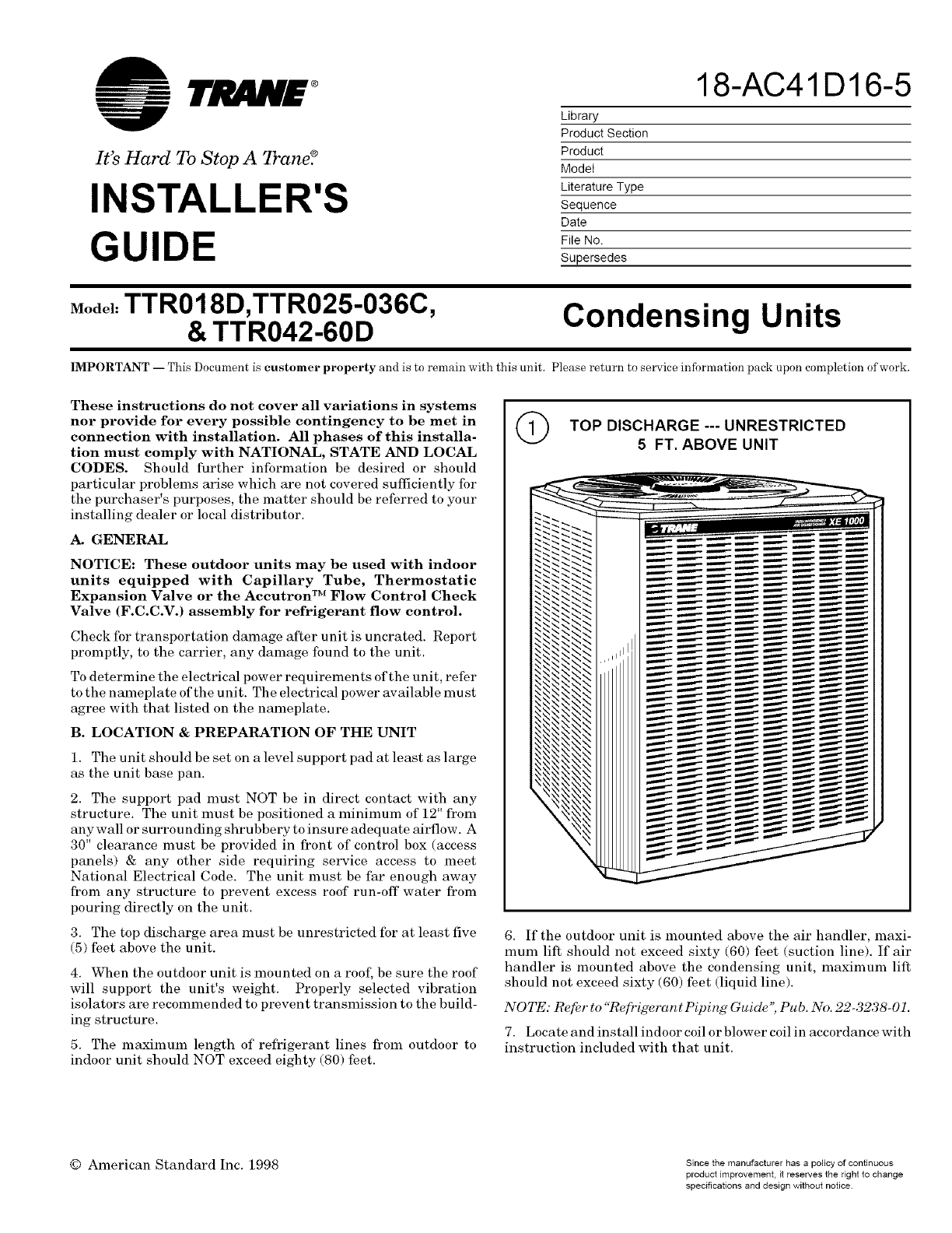
3. The top discharge area must be unrestricted for at least five
(5) feet above the unit.
4. When the outdoor unit is mounted on a roof, be sure the roof
will support the unit's weight. Properly selected vibration
isolators are recommended to prevent transmission to the build-
ing structure.
5. The maximmn length of refrigerant lines from outdoor to
indoor unit should NOT exceed eighty (80) feet.
QTOP DISCHARGE --- UNRESTRICTED
5 FT. ABOVE UNIT
6. If the outdoor unit is mounted above the air handler, maxi-
mum lift should not exceed sixty (60) feet (suction line). If air
handler is mounted above the condensing unit, maximum lilt
should not exceed sixty (60) feet (liquid line).
NOTE: Refi_r to "Re[i'igerant Piping Guide'; Pub. No. 22-3238-01.
7. Locate and install indoor coil or blower coil in accordance with
instruction included with that unit.
© American Standard Inc. 1998 Since the manufacturer has a policy of continuous
product improvement, it reserves the right to change
specifications and design without notice.
INSTALLER'S GUIDE
C. ACCUTRON TM FLOW CONTROL VALVE
If the indoor unit System Refrigerant Flow control is an
Accutron TM orifice and check valve assembly, an orifice size
change may be necessary.
The outdoor model determines the required orifice size. Check
the listed orifice size on nameplate of the selected outdoor model.
If the indoor u nit is factory shipped with a different orifice size,
the orifice must be changed to obtain system rated performance.
IMPORTANT: The outdoor unit is shipped with the proper size
orifice and a stick-on orifice size label in an envelope attached to
the outdoor unit. Outdoor unit nameplate will have correct
orifice size specified as BAYFCCV --- A for rated performance.
D. INSTALLING REFRIGERANT LINES
Condensing units have provisions lbr braze connections.
Pressure taps are provided on the service valves of outdoor unit
for compressor suction and liquid pressures.
The indoor end of recommended refrigerant line sets may be
straight or with a 90 degree bend, depending upon situation
requirements. This should be thoroughly checked out before
ordering refrigerant line sets.
The gas line must always be insulated.
The units are Ihctory charged with the system charge required
when using twenty-five (25) feet of connecting line. Unit name-
plate charge is the same. If final refrigerant charge adjustment
is necessary, use the Charge Charts in the outdoor unit Service
Facts.
1. Determine the most practical way to run the lines.
2. Consider types of bends to be made and space limitations.
NOTE: Lasce diameter tubing will be very difficult to rebend once
it has been shaped.
3. Determine the best starting point Ibr routing the refrigerant
tubing--INSIDE OR OUTSIDE THE STRUCTURE.
4. Provide a pull-thru hole of sufficient size to allow both liquid
and gas lines plus fittings to clear. The location of this hole (if
practical) should be just about the wall plate which is resting on
the Ibundation.
5. Be sure the tubing is of sufficient length.
6. Uncoil the tubing --- do not kink or dent.
7. Route the tubing making all required bends and properly
secure the tubing before making connections.
8. To prevent a noise within the building structure due to
vibration transmission from the refrigerant lines, the following
precautions should be taken:
a. When the refrigerant lines have to be Ihstened to floor
joists or other framing in a structure, use isolation type hangers.
b. Isolation hangers should also be used when refrigerant
lines are run in stud spaces or enclosed ceilings.
c. Where the refrigerant lines run through a wall or sill, they
should be insulated and isolated.
d. Isolate the lines from all ductwork.
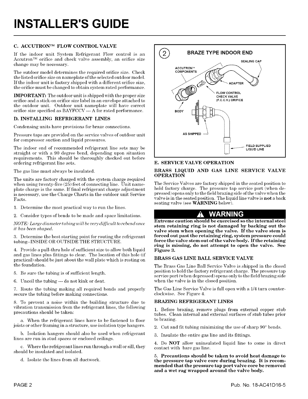
@BRAZE TYPE INDOOR END
SEALING CAP
ACCUTRON TM
COMPONENTS
'_ FLOW CONTROL
CHECK VALVE
(F.C.C,V.) ORIFICE
FIELD SUPPLIED
LIQUID LINE
E. SERVICE VALVE OPERATION
BRASS LIQUID AND GAS LINE SERVICE VALVE
OPERATION
The Service Valves are lhctory shipped in the seated position to
hold ihctory charge. The pressure tap service port (when de-
pressed) opens only to the field brazing side of the valve when the
valve is in the seated position. The liquid line valve is not a back
seating valve (see WARNING below).
Extreme caution should be exercised so the internal steel
stem retaining ring is not damaged by backing out the
valve stem when opening the valve. If the valve stem is
forced out past the retaining ring, system pressure could
force the valve stem out of the valve body. If the retaining
ring is missing, do not attempt to open the valve. See
Figure 3.
BRASS GAS LINE BALL SERVICE VALVE
The Brass Gas Line Ball Service Valve is shipped in the closed
position to hold the factory refrigerant charge. The pressure tap
service port (when depressed) opens only to the field brazing side
when the valve is in the closed position.
The Gas Line Service Valve is full open with a 1/4 turn counter-
clockwise. See Figure 4.
BRAZING REFRIGERANT LINES
1. Before brazing, remove plugs li'om external copper stub
tubes. Clean internal and external surfaces of stub tubes prior
to brazing.
2. Cut and fit tubing minimizing the use of sharp 90 ° bends.
3. Insulate the entire gas line and its fittings.
4. Do NOT allow uninsulated liquid line to come in direct
contact with bare gas line.
5. Precautions should be taken to avoid heat damage to
the pressure tap valve core during brazing. It is recom-
mended that the pressure tap port valve core be removed
and a wet rag wrapped around the valve body.
PAGE 2 Pub. No. 18-AC41D16-5
INSTALLER'S GUIDE
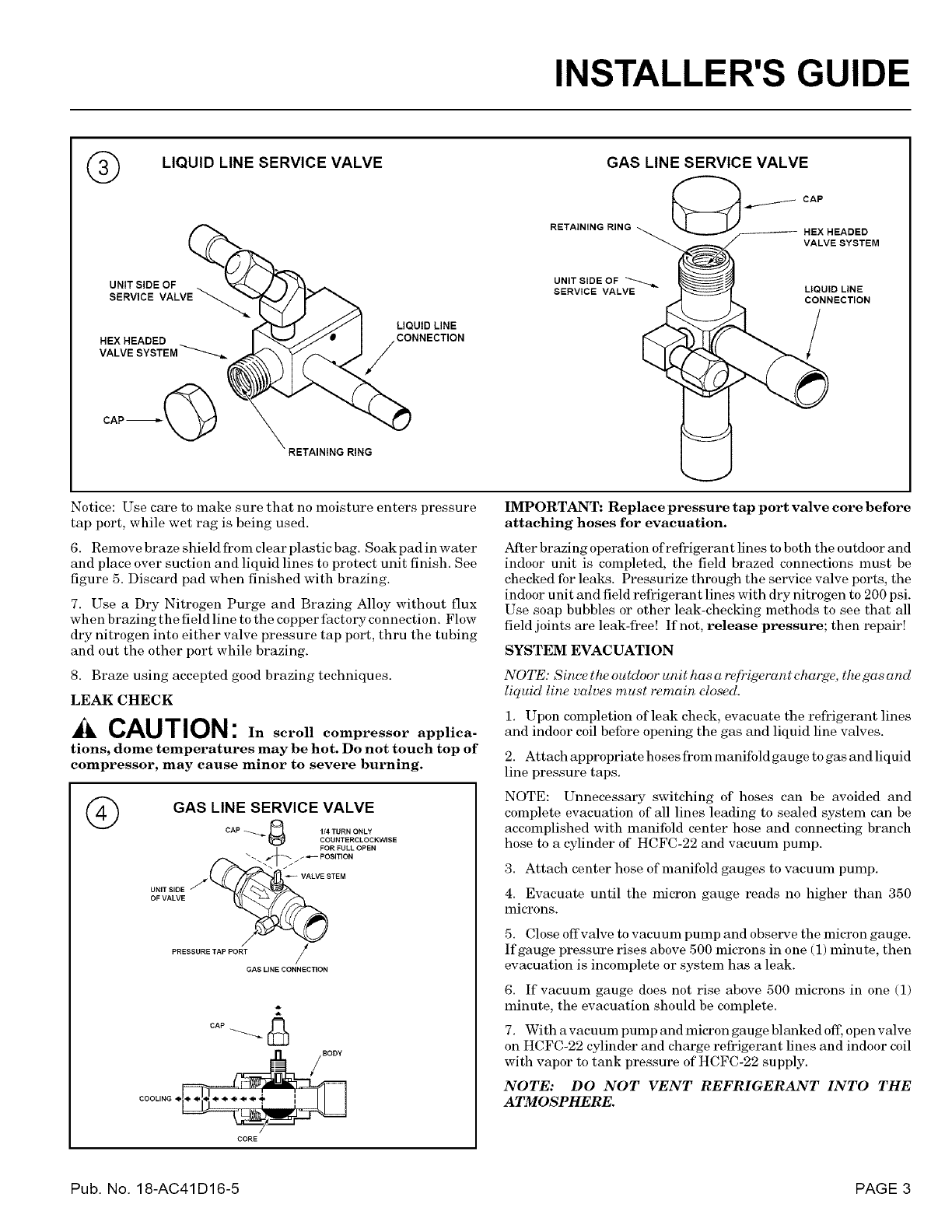
®LIQUID LINE SERVICE VALVE GAS LINE SERVICE VALVE
CAP
RETAINING RING HEXHEADED
VALVE SYSTEM
UNtTSIDE OF
SERVICE VALVE_
HEX HEADED
VALVE
CAP'_"_
LIQUID LINE
CONNECTION
UNIT SIDE OF
SERVICE VALVE LIQUID LINE
CONNECTION
Notice: Use care to make sure that no moisture enters pressure
tap port, while wet rag is being used.
6. Remove braze shield from clear plastic bag. Soak pad in water
and place over suction and liquid lines to protect unit finish. See
figure 5. Discard pad when finished with brazing.
7. Use a Dry Nitrogen Purge and Brazing Alloy without flux
when brazing the field line to the copper factory connection. Flow
dry nitrogen into either valve pressure tap port, thru the tubing
and out the other port while brazing.
8. Braze using accepted good brazing techniques.
LEAK CHECK
CAUTION: In scroll compressor applica-
tions, dome temperatures may be hot. Do not touch top of
compressor, may cause minor to severe burning.
©GAS LINE SERVICE VALVE
CAP _ J_ 114TURN ONLY
COUNTERCLOCKWISE
/
UNIT SIDE
OF VALVE
#
PRESSURE TAP PORT /'
/
GAS LINE CONNECTION
CAP _ &
CORE
IMPORTANT: Replace pressure tap port valve core before
attaching hoses for evacuation.
After brazing operation of refrigerant lines to both the outdoor and
indoor unit is completed, the field brazed connections must be
checked fbr leaks. Pressmize through the service valve ports, the
indoor u nit and field refrigerant lines with dry nitrogen to 200 psi.
Use soap bubbles or other leak-checking methods to see that all
field joints are leak-free! If not, release pressure; then repair!
SYSTEM EVACUATION
NOTE: Since the outdoor unit has a re[?igerant charde, the gas and
liquid line vcllves must remain closed.
1. Upon completion of leak check, evacuate the refrigerant lines
and indoor coil before opening the gas and liquid line valves.
2. Attach appropriate hoses from manifold gauge to gas and liquid
line pressure taps.
NOTE: Unnecessm'y switching of hoses can be avoided and
complete evacuation of all lines leading to sealed system can be
accomplished with manifold center hose and connecting branch
hose to a cylinder of HCFC-22 and vacuum pump.
3. Attach center hose of manifold gauges to vacuum pump.
4. Evacuate until the micron gauge reads no higher than 350
microns.
5. Close offvalve to vacuum pump and observe the micron gauge.
If gauge pressure rises above 500 microns in one (1) minute, then
evacuation is incomplete or system has a leak.
6. If vacuum gauge does not rise above 500 microns in one (1)
minute, the evacuation should be complete.
7. With a vacuum pump and micron gauge blm_ked off; open valve
on HCFC-22 cylinder and charge refrigerant lines and indoor coil
with vapor to tank pressure of HCFC-22 supply.
NOTE: DO NOT VENT REFRIGERANT INTO THE
ATMOSPHERE.
Pub. No. 18-AC41D16-5 PAGE 3
INSTALLER'S GUIDE
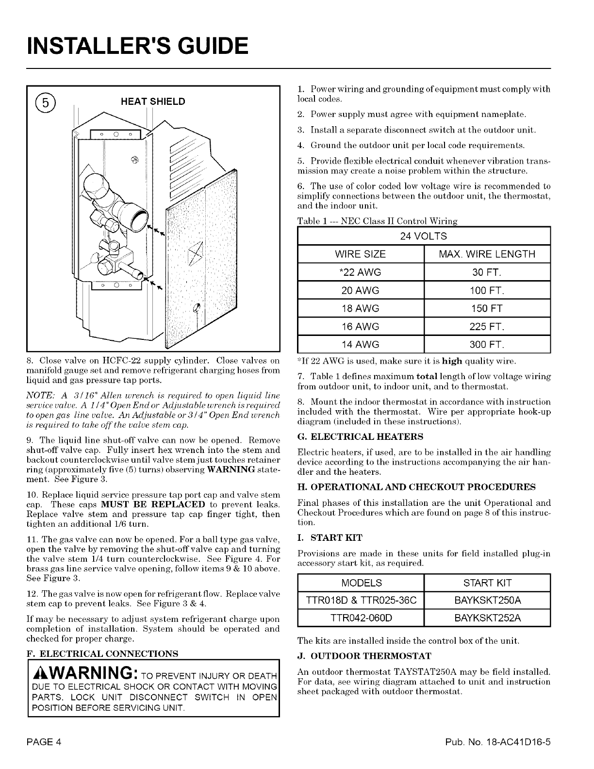
(_ HEAT SHIELD
8. Close valve on HCFC-22 supply cylinder. Close valves on
manifold gauge set and remove refrigerant charging hoses from
liquid and gas pressure tap ports.
NOTE: A 3/16" Allen wrench is required to open liquid line
service valve. A 1/4" Open End or Adjustable wrench is required
to open gas line valve. An Adjustable or 3 /4" Open End u._nch
is required to take aff the valve stem cap.
9. The liquid line shut-off valve can now be opened. Remove
shut-off valve cap. Fully insert hex wrench into the stem and
backou t cou nterclockwise until valve stem just tou ches retainer
ring (approximately five (5) turns) observing WARNING state-
ment. See Figure 3.
10. Replace liquid service pressure tap port cap and valve stem
cap. These caps MUST BE REPLACED to prevent leaks.
Replace valve stem and pressure tap cap finger tight, then
tighten an additional 1/6 turn.
11. The gas valve can now be opened. For a ball type gas valve,
open the valve by removing the shut-off valve cap and turning
the valve stein 1/4 turn counterclockwise. See Figure 4. For
brass gas line service valve opening, follow items 9 & 10 above.
See Figure 3.
12. The gas valve is now open for refrigerant flow. Replace valve
stem cap to prevent leaks. See Figure 3 & 4.
If may be necessary to adjust system refi'igerant charge upon
completion of installation. System should be operated and
checked for proper charge.
F. ELECTRICAL CONNECTIONS
WARN ING:TO PREVENT INJURY OR DEATH
ETO_t CT%%S;O%O OONT TW,T 20
POS T ON BEFORE SERV C NG UN T.
1. Power wiring and grounding of equipment must comply with
local codes.
2. Power supply must agree with equipment nameplate.
3. Install a separate disconnect switch at the outdoor unit.
4. Ground the outdoor unit per local code requirements.
5. Provide flexible electrical conduit whenever vibration trans-
mission may create a noise problem within the structure.
6. The use of color coded low voltage wire is recommended to
simplil_¢ connections between the outdoor unit, the thermostat,
and the indoor unit.
Table 1 --- NEC Class II Control Wiring
24 VOLTS
WIRE SIZE MAX. WIRE LENGTH
*22 AWG 30 FT.
20 AWG 100 FT.
18 AWG 150 FT
16 AWG 225 FT.
14 AWG 300 FT.
*If 22 AWG is used, make sure it is high quality wire.
7. Table I defines maximum total length of low voltage wiring
from outdoor unit, to indoor unit, and to thermostat.
8. Mount the indoor thermostat in accordance with instruction
included with the thermostat. Wire per appropriate hook-up
diagram (included in these instructions).
G. ELECTRICAL HEATERS
Electric heaters, if used, are to be installed in the air handling
device according to the instructions accompanying the air han-
dler and the heaters.
H. OPERATIONAL ANDCHECKOUTPROCEDURES
Final phases of this installation are the unit Operational and
Checkout Procedures which are Ibund on page 8 of this instruc-
tion.
I. START KIT
Provisions are made in these units for field installed plug4n
accessory start kit, as required.
MODELS START KIT
TTR018D & TTR025-36C BAYKSKT250A
TTR042-060D BAYKSKT252A
The kits are installed inside the control box of the unit.
J. OUTDOOR THERMOSTAT
An outdoor thermostat TAYSTAT250A may be field installed.
For data, see wiring diagram attached to unit and instruction
sheet packaged with outdoor thermostat.
PAGE 4 Pub. No. 18-AC41D16-5
INSTALLER'S GUIDE
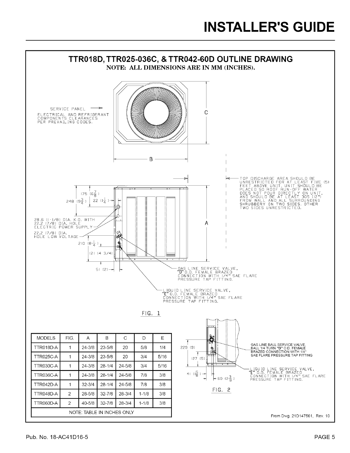
TTR018D, TTR025-036C, & TTR042-60D OUTLINE DRAWING
NOTE: ALL DIMENSIONS ARE IN MM INCHES).
SERVICE PANEL
ELECTRICAL AND REFRIGERANT
COMPONENTS CLEARANCES
PER PREVAILING CODES.
248 [95 22
28.6 (I I/'8} D[A. K.O. WITH
22.2 [7/8) D[A. HOLE
ELECTRIC POWER
22.2 [7/8) DiA.
HOLE LOW
210 (8_
l21 [4 3/41
SI
q
=o o. .
ii ii
ii ii
II
_TOP DISCHARGE AREA SHOULD BE
UNRESTRICTED FOR AT LEAST FiVE [5]
I FEET ABOVE UNIT. UNIT SHOULD BE
PLACEO SO ROOF RUN OFF WATER
DOES NOT POUR DIRECTLY ON UNIT,
AND SHOULD BE AT LEAST 305 (12"}
FROM WALL AND ALL SURROUNDING
SHRUBBERY ON TWO SIDES. OTHER
TWO SIDES UNRESTRICTED.
GAS LINE SERVICE VALVE,
"D'0.D. FEMALE BRAZED
CONNECTION WITH I/4" SAE FLARE
PRESSURE TAP FITTING.
LIQUID LINE SERVICE VALVE,
"E"0.D. FEMALE BRAZED
CONNECTION WITH I/'4" SAE FLARE
PRESSURE TAP FITTING.
FIG, i
MODELS FIG. A B C D E
TTR018D-A 1 24-3/8 23-5/8 20 5/8 !/4
TTR025C-A 1 24-3/8 23-5t8 20 3/4 5/!6
TTR030C-A 1 24-3/8 28-1/4 24-5/8 3/4 5/!6
TTR036C-A 1 24-3/8 28-1/4 24-5/8 7/8 3/8
TTR042D-A 1 32-3/4 28-1/4 24-5/8 7/8 3/8
TTR048D-A 2 28-5/8 32-7/8 28-3/4 1-118 3/8
TTR060D-A 2 40-5/8 32-7/8 28-3/4 1-1t8 3/8
NOTE: TABLE IN INCHES ONLY
229 (9]
127 (5)
41 (1_)_
FIG. 2
From Dwg. 21D147561, Rev 10
Pub. No. 18-AC41D16-5 PAGE 5
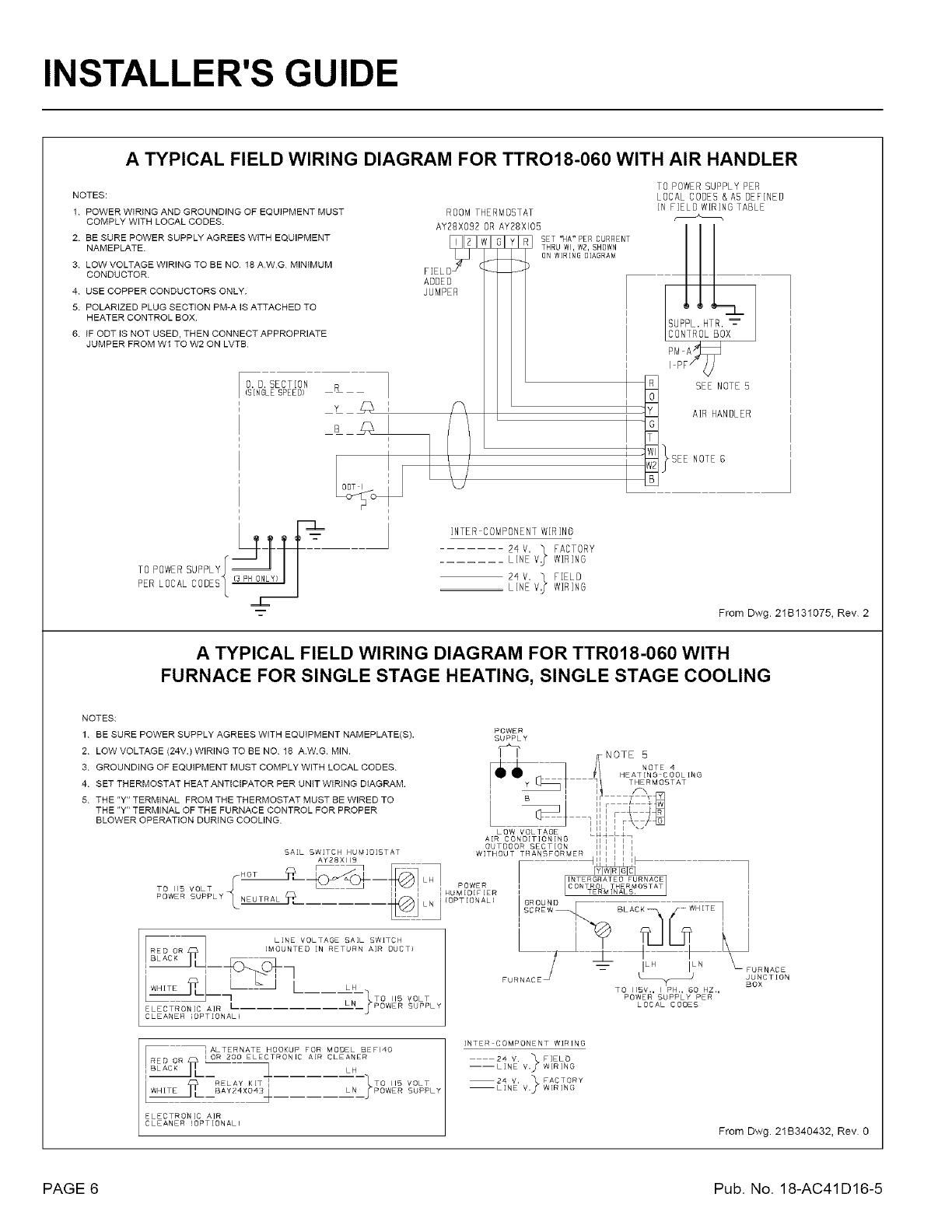
INSTALLER'S GUIDE
A TYPICAL FIELD WIRING DIAGRAM FOR TTRO18-060 WITH AIR HANDLER
NOTES:
1 POWER WIRING AND GROUNDING OF EQUIPMENT MUST
2
3
4
5
6
COMPLY WITH LOCAL CODES.
BE SURE POWER SUPPLY AGREES WITH EQUIPMENT _F_q[
o?
NAMEPLATE.
LOW VOLTAGE WIRING TO BE NO 18 AWG MINIMUM (
CONDUCTOR. F[EL
ADDED
USE COPPER CONDUCTORS ONLY. JUMPER
POLARIZED PLUG SECTION PM-A IS ATTACHED TO
HEATER CONTROL BOX
IF ODT IS NOT USED, THEN CONNECT APPROPRIATE
JUMPER FROM WI TO W2 ON LVTB
O. O. SECTION RI
)SINGLE SPEED) I
ROOM THERMOSTAT
AY28X092 OR AY28XI05
SET 'NA" PER CURRENT
THRU Wl, W2, SHOWN
ON WIRING DIAGRAM
INTER COMPONENT WIRING
24 V. "_ FACTORY
....... LINE V_ WIRING
24 V. "_ FIELD
LINE V_ WIRING
_L
%-
TO POWER SUPPLY PER
LOCAL CODED & AS DEFINED
IN FIELD WIRING TABLE
SEE NOTE 5
AIR HANDLER
NOTE 6
From Dwg. 21B131075, Rev2
A TYPICAL FIELD WIRING DIAGRAM FOR TTR018-060 WITH
FURNACE FOR SINGLE STAGE HEATING, SINGLE STAGE COOLING
NOTES:
1 BE SURE POWER SUPPLY AGREES WITH EQUIPMENT NAMEPLATE(S). POWER
SUPPLY
2 LOW VOLTAGE (24V.) WIRING TO BE NO 18 A.W.G. MIN. _ N OTE 5
3 GROUNDING OF EQUIPMENT MUST COMPLY WFH LOCAL CODES _ _- l! NOTE 4
HEATING COOLING
y_ THERMOSTAT4 SETTHERMOSTATHEATANTICIPATORPERUNITWIRINGDIAGRAM _ I _ r_
5 THE "Y" TERMINAL FROM THE THERMOSTAT MUST BE WIRED TO B I ir T _
.....
THE "Y" TERMINAL OF THE FURNACE CONTROL FOR PROPER i I I
BLOWER OPERATION DURING COOLING • I I • \
LOW VOLTAGE LI4' L / ""
AIR CONDITIONING I1_ I I_
OUTDOOR SECTION II I I I i
SAiL SWITCH HUMIOISTAT WiTHDUT TRANSFDRMER I I I I I
AY28XII9 4111 I I I_
_{_ -- h_ LN j IMTERGRATEO FURNACE
TO IIS VOLT II I I HUMIDIFIER TERMIN_L'S.
POWER SUPPLY IDPTIDNALI
I
ELECTRONIC AIR L
CLEANER _OPTIONAL)
] ALTERNATE HOOKUP FOR MODEL BEFI40
RED OR 3LOR2R 2OO ELECTRONIC AIR CLEANER
LH
---}TG.,, VOLT
RELAY KIT I
BAY24X043_ LM POWER SUPPLY
ELECTRONIC AIR
CLEANER ',OPTiON ALI
FURNACE
INTER COMPONENT WIRING
TO 115V., I PH., 60 HZ.,
POWER SUPPLY PER
LOCAL CODES
FURNACE
JUNCTION
BOX
From Dwg. 21B340432, Rev 0
PAGE 6 Pub. No. 18-AC41D16-5
INSTALLER'S GUIDE
CHECKOUT PROCEDURE
After installation has been completed, it is recommended that the entire system be checked against the
following list:
1. Refrigerant Line, Leak checked .......................................................................................................... [ ]
2. Suction Lines and Fittings properly insulated ...................................................................................... [ ]
3. Have all Refrigerant Lines been secured and isolated properly? ........................................................ [ ]
4. Have passages through masonry been sealed? If mortar is used, prevent mortar from
coming into direct contact with copper tubing ..................................................................................... [ ]
5. Indoor coil drain line drains freely. Pour water into drain pan ............................................................. [ ]
6. Supply registers and return grilles open and unobstructed ................................................................. [ ]
7. Return air filter installed ...................................................................................................................... [ ]
8. Thermostat thermometer is accurate. Check against a reliable thermometer. Adjust
per instructions with thermostat .......................................................................................................... [ ]
9. Is correct speed tap being used? (Indoor blower motor) ..................................................................... [ ]
SYSTEM OPERATIONAL CHECK
OPERATING PRESSURES: After the unit has operated in the cooling mode for a short period of time, install
pressure gauges on the gauge ports of the discharge and suction line valves. Check the suction and discharge
pressures and compare them to the normal operating pressures provided in the unit's Service Facts.
NOTE: Use the pressures from Service Facts to determine the unit refrigerant charge.
To charge the system accurately, use superheat charging, or pressures
depending on flow control.
1. Except as required for safety while servicing: DO NOT OPEN SYSTEM DISCONNECT SWITCH.
SUPPLEMENTARY HEATERS CHECKOUT PROCEDURES, IF USED
DOES HEATER REQUIRE A SEPARATE CIRCUIT?
1. Be sure the fused disconnect switch is "OFF," and safety label (if any) is attached ................................ [ ]
2. Check on field wiring for sound connections and grounding according to codes ..................................... [ ]
3. Check fuses for proper size per nameplate specifications ..................................................................... [ ]
4. Check control box panel-- in place and secured .................................................................................. [ ]
NOTE: OPERATION OF HEATERS MUST BE CHECKED DURING THE OPERATION CHECKOF THE TOTAL
SYSTEM.
Pub. No. 18-AC41D16-5 PAGE 7
INSTALLER'S GUIDE
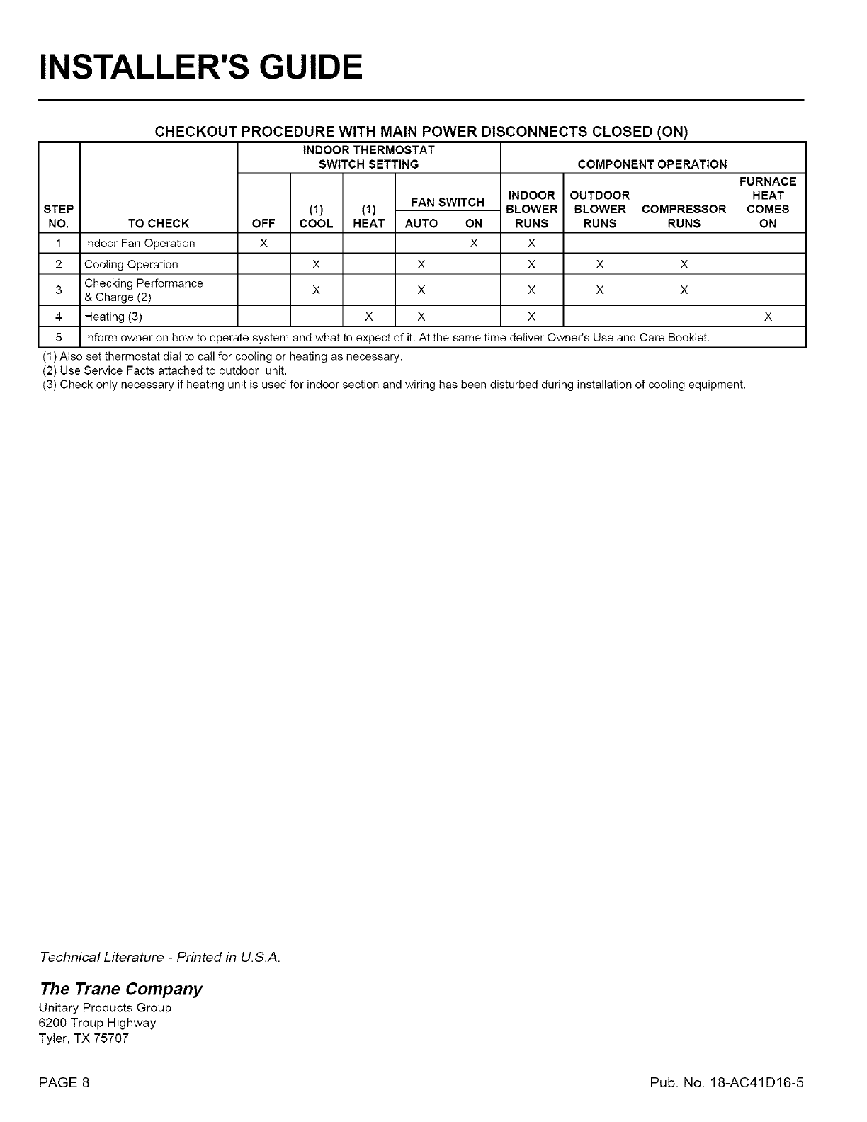
STEP
NO.
1
CHECKOUT PROCEDURE WITH MAIN POWER DISCONNECTS CLOSED (ON)
INDOOR THERMOSTAT
SWITCH SETTING COMPONENT OPERATION
TO CHECK
Indoor Fan Operation
Cooling Operation
Checking Performance
& Charge (2)
Heating (3)
OFF
X
(1) (1)
COOL HEAT
X
X
FAN SWITCH
AUTO ON
X
X
X
X
INDOOR
BLOWER
RUNS
X
OUTDOOR
BLOWER
RUNS
X
X
COMPRESSOR
RUNS
X
X
5 Inform owner on how to operate system and what to expect of it. At the same time deliver Owner's Use and Care Booklet.
(1) Also set thermostat dial to call for cooling or heating as necessary,
(2) Use Service Facts attached to outdoor unit,
(3) Check only necessary if heating unit is used for indoor section and wiring has been disturbed during installation of cooling equipment,
FURNACE
HEAT
COMES
ON
Technical Literature -Printed in U.S.A.
The Trane Company
Unitary Products Group
6200 Troup Highway
Tyler, TX 75707
PAGE 8 Pub. No. 18-AC41D16-5
