TRANE Furnace/Heater, Gas Manual L0903218
User Manual: TRANE TRANE Furnace/Heater, Gas Manual TRANE Furnace/Heater, Gas Owner's Manual, TRANE Furnace/Heater, Gas installation guides
Open the PDF directly: View PDF ![]() .
.
Page Count: 2
IIIIII IIIIIIIIIIIIII IIIIII
1 8- CH2 2 D2- 6
BAYVENT200B
For use with *UX, *DX, *UY, AND *DY models
DIRECT VENT FURNACE
SiDE WALL VENT KiT
*__First letter ma be "A", "C" or "T"
ALL phases of this installation must comply with NATIONAL, STATE AND LOCAL CODES
IMPORTANT -- This Document is customer property and is to remain with this unit.
P]ease return to service information pack upon comp]etion of' work.
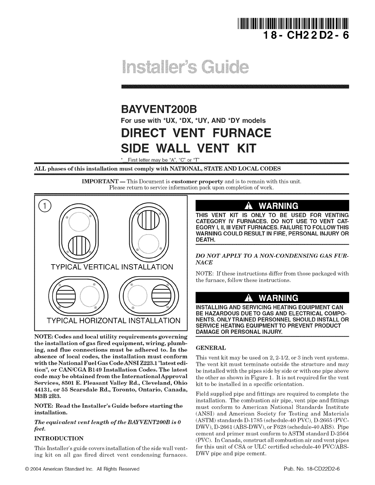
TYPICAL VERTICAL INSTALLATION
TYPICAL HORIZONTAL INSTALLATION
NOTE: Codes and local utility requirements governing
the installation of gas fired equipment, wiring, plumb-
ing, and flue connections must be adhered to. In the
absence of local codes, the installation must conform
with the National Fuel Gas CodeANSI Z223.1 'latest edi-
tion", or CAN/CGA B149 Installation Codes. The latest
code may be obtained from the InternationalApproval
Services, 8501 E. Pleasant Valley Rd, Cleveland, Ohio
44131, or 55 Searsdale Rd., Toronto, Ontario, Canada,
M3B 2R3.
NOTE: Read the Installer's Guide before starting the
installation.
The equivalent vent length of the BAYVENT2OOB is 0
feet.
INTRODUCTION
This Installer's guide covers installation of the side wall vent-
ing kit on all gas fired direct vent condensing furnaces.
THIS VENT KIT IS ONLY TO BE USED FOR VENTING
CATEGORY IV FURNACES. DO NOT USE TO VENT CAT-
EGORY I, II, Ill VENT FURNACES. FAILURE TO FOLLOWTHIS
WARNING COULD RESULT IN FIRE, PERSONAL INJURY OR
DEATH.
DO NOT APPLY TO A NON-CONDENSING GAS FUR-
NACE
NOTE: If these instructions differ from those packaged with
the furnace, follow these instructions.
INSTALLING AND SERVICING HEATING EQUIPMENT CAN
BE HAZARDOUS DUE TO GAS AND ELECTRICAL COMPO-
NENTS. ONLYTRAINED PERSONNEL SHOULD INSTALL OR
SERVICE HEATING EQUIPMENT TO PREVENT PRODUCT
DAMAGE OR PERSONAL INJURY.
GENERAL
This vent kit may be used on 2, 2-1/2, or 3 inch vent systems.
The vent kit must terminate outside the structure and may
be installed with the pipes side by side or with one pipe above
the other as shown in Figure 1. It is not required for the vent
kit to be installed in a specific orientation.
Field supplied pipe and fittings are required to complete the
installation. The combustion air pipe, vent pipe and fittings
must conform to American National Standards Institute
(ANSI) and American Society for Testing and Materials
(ASTM) standards D-1785 (schedule-40 PVC), D-2665 (PVC-
DWV), D-2661 (ABS-DWV), or F628 (schedule-40 ABS). Pipe
cement and primer must conform to ASTM standard D-2564
(PVC). In Canada, construct all combustion air and vent pipes
for this unit of CSA or ULC certified schedule-40 PVC/ABS-
DWV pipe and pipe cement.
© 2004 American Standard inc. All Rights Reserved Pub. No. 18-CD22D2-6
INSTALLATION - Side Wahl Vent Kit
1. Determine the best location for the vent kit.
NOTE: In addition to all applicable local codes, consider the
following when determining the vent kit location:
• The vent kit should be positioned where the vent
vapors and flue gas condensate will not damage building
materials, plants, shrubs, or air conditioning equipment.
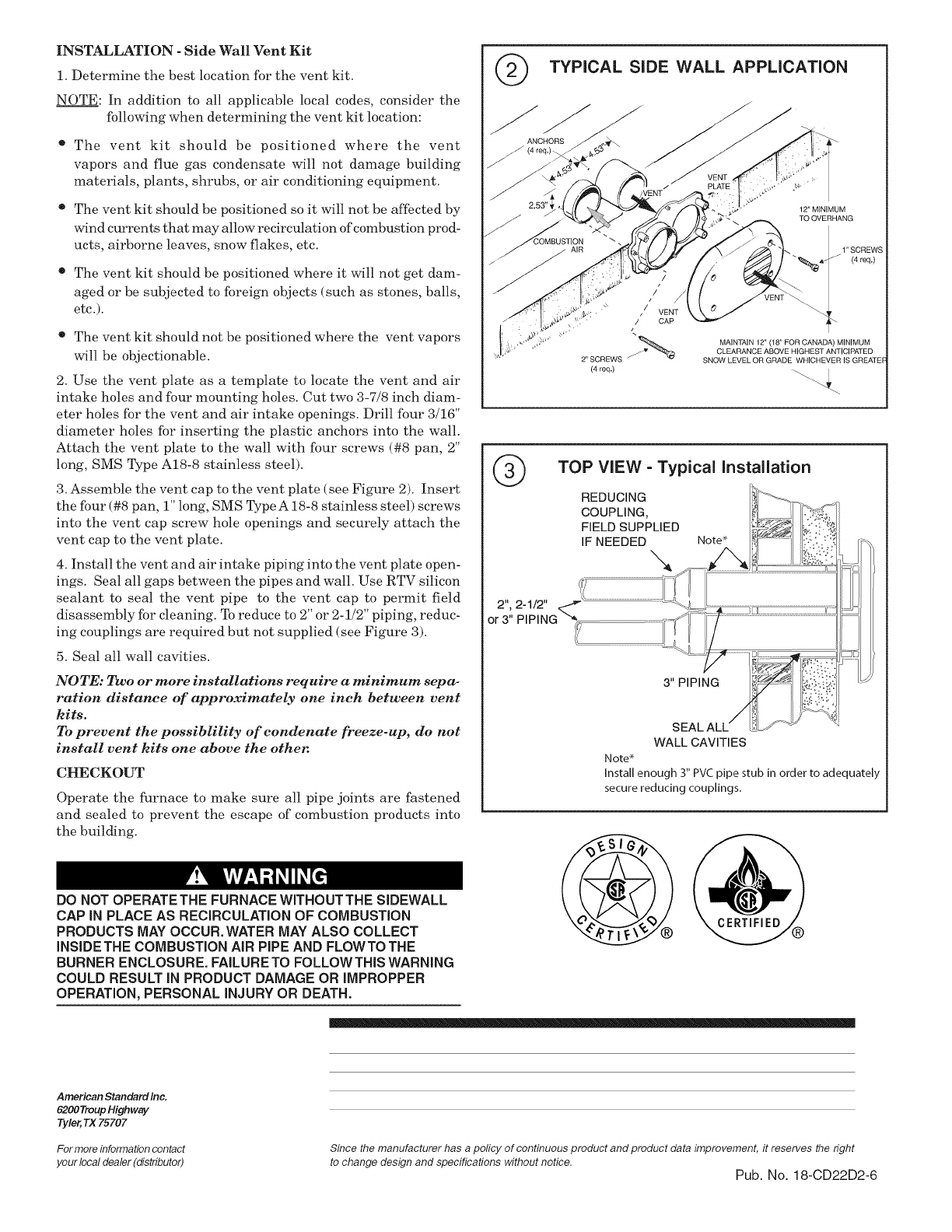
TYPICAL SiDE WALL APPLiCATiON
ANCHORS
• The vent kit should be positioned so it will not be affected by
wind currents that may allow recireulation of combustion prod-
ucts, airborne leaves, snow flakes, etc.
• The vent kit should be positioned where it will not get dam-
aged or be subjected to foreign objects (such as stones, balls,
etc.).
• The vent kit should not be positioned where the vent vapors
will be objectionable.
2. Use the vent plate as a template to locate the vent and air
intake holes and four mounting holes. Cut two 3-7/8 inch diam-
eter holes for the vent and air intake openings. Drill four 3/16"
diameter holes for inserting the plastic anchors into the wall.
Attach the vent plate to the wall with four screws (#8 pan, 2"
long, SMS Type A18-8 stainless steel).
3. Assemble the vent cap to the vent plate (see Figure 2). Insert
the four (#8 pan, 1" long, SMS TypeA 18-8 stainless steel) screws
into the vent cap screw hole openings and securely attach the
vent cap to the vent plate.
4. Install the vent and air intake piping into the vent plate open-
ings. Seal all gaps between the pipes and wall. Use RTV silicon
sealant to seal the vent pipe to the vent cap to permit field
disassembly for cleaning. To reduce to 2" or 2-1/2" piping, reduc-
ing couplings are required but not supplied (see Figure 3).
5. Seal all wall cavities.
NOTE: Two or more installations require a minimum sepa-
ration distance of approximately one inch between vent
kits.
To prevent the possiblility of condenate freeze-up, do not
install vent kits one above the other.
CHECKOUT
Operate the furnace to make sure all pipe joints are thstened
and sealed to prevent the escape of combustion products into
the building.
DO NOT OPERATETHE FURNACE WffHOUTTHE SIDEWALL
CAP iN PLACE AS RECIRCULATION OF COMBUSTION
PRODUCTS MAY OCCUR. WATER MAY ALSO COLLECT
iNSIDE THE COMBUSTION AIR PIPE AND FLOWTO THE
BURNER ENCLOSURE. FAILURE TO FOLLOW THB WARNING
COULD RESULT iN PRODUCT DAMAGE OR IMPROPPER
OPERATION, PERSONAL INJURY OR DEATH.
®
2", 2-1/2"
or 3"
12" MINIMUM
TO OVERHANG
1" SCREWS
(4 req.)
2" SCREWS
(4 req.)
/
/
/CAP
L
MAINTAIN 12" (18" FOR CANADA) MINIMUM
CLEARANCE ABOVE HIGHEST ANTICIPATED
SNOW LEVEL OR GRADE WHICHEVER IS GREATEF
TOP ViEW -Typical installation
REDUCING
COUPLING,
FIELD SUPPLIED
IF NEEDED\, Note*
3" PIPING
.....I
WALL CAVITIES
Note*
Install enough 3" PVC pipe stub in order to adequately
secure reducing couplings.
American Standard Inc.
6200Troup Highway
Tyler, TX 75707
For more information contact
your loca! dealer (distributed
Since the manufacturer has a policy of continuous product and product data linprovement, it reserves the right
to change design and specifications without notice. Pub. No. 18-CD22D2-6
