TRANE Air Conditioner/heat Pump(outside Unit) Manual L0904664
User Manual: TRANE TRANE Air conditioner/heat pump(outside unit) Manual TRANE Air conditioner/heat pump(outside unit) Owner's Manual, TRANE Air conditioner/heat pump(outside unit) installation guides
Open the PDF directly: View PDF ![]() .
.
Page Count: 8
18-AC50D1-3
Condensing n
4TTX3; 4TTX4
ALL phases of this installation must comply with NATIONAL, STATE AND LOCAL CODES
IMPORTANT -- This Document is customer property and is to remain with this unit. Please return to service information
pack upon completion of work.
These instructions do not cover all variations in
systems nor provide for every possible contingency to
be met in connection with installation. All phases of
this installation must comply with NATIONAL, STATE
AND LOCAL CODES. Should further information be
desired or should particular problems arise which are not
covered sufficiently for the purchaser's purposes, the matter
should be referred to your installing dealer or local distributor.
A. GENERAL
The following instructions cover 4TTX3; 4TTX4 Condensing
Units.
NOTICE:
These outdoor units may be used with indoor units
equipped with Thermostatic Expansion Valve or
Accutron TM Flow Control Check Valve (F.C.C.V.) assembly
for refrigerant flow control only.
These units use R-410A refrigerant which operates at 50
to 70% higher pressures than R-22. Use only R-410A
approved service equipment. Refrigerant cylinders are
painted a "Rose" color to indicate the type of refrigerant
and may contain a"dip" tube to allow for charging of liquid
refrigerant into the system. All R-410A systems use a POE
oil that readily absorbs moisture from the atmosphere. To
limit this "hygroscopic" action, the system should remain
sealed whenever possible. Never break a vacuum with air
and always change the driers when opening the system for
component replacement.
Check for transportation damage after unit is uncrated.
Report promptly, to the carrier, any damage found to the unit.
To determine the electrical power requirements of the unit,
refer to the nameplate of the unit. The electrical power
available must agree with that listed on the nameplate.
B. LOCATION &PREPARATION
OF THE UNiT
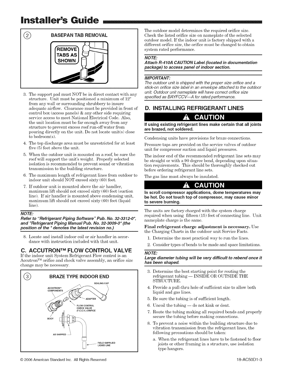
1. When removing unit from the pallet, notice the tabs on
the basepan. Remove tabs by cutting with a sharp tool as
shown in Figure 2 (see page 2).
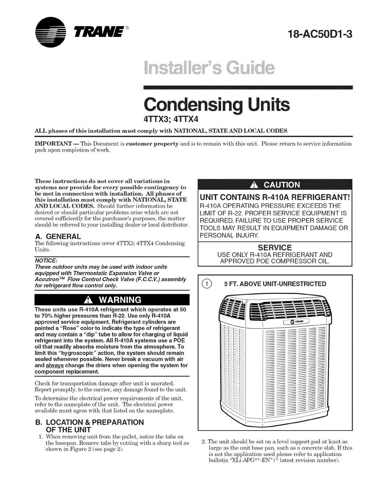
UNiT CONTAINS R-410A REFRIGERANT!
R-410A OPERATING PRESSURE EXCEEDS THE
LiMiT OF R-22. PROPER SERVICE EQUIPMENT IS
REQUIRED. FAILURE TO USE PROPER SERVICE
TOOLS MAY RESULT IN EQUIPMENT DAMAGE OR
PERSONAL INJURY.
SERVICE
USE ONLY R-410A REFRIGERANT AND
APPROVED POE COMPRESSOR OiL.
5 FT. ABOVE UNIT=UNRESTRICTED
2. The unit should be set on a level support pad at least as
large as the unit base pan, such as a concrete slab. If this
is not the application used please refer to application
bulletin "XLi-APG**-EN" (* latest revision number).
|nsta||er's Guide
@
3. The support pad must NOT be in direct contact with any
structure. Unit must be positioned a minimum of 12"
from any wall or surrounding shrubbery to insure
adequate airflow. Clearance must be provided in front of
control box (access panels) & any other side requiring
service access to meet National Electrical Code. Also,
the unit location must be far enough away from any
structure to prevent excess roof run-offwater from
pouring directly on the unit. Do not locate unit(s) close
to bedroom(s).
4. The top discharge area must be unrestricted for at least
five (5) feet above the unit.
5. When the outdoor unit is mounted on a roof', be sure the
roof will support the unit's weight. Properly selected
isolation is recommended to prevent sound or vibration
transmission to the building structure.
6. The maximum length of refrigerant lines from outdoor to
indoor unit should NOT exceed sixty (60) feet.
7. If outdoor unit is mounted above the air handler,
maximum lift should not exceed sixty (60) feet (suction
line). If air handler is mounted above condensing unit,
maximum lift should not exceed sixty (60) feet (liquid
line).
NOTE:
Refer to "Refrigerant Piping Software" Pub. No. 32-3312-0",
and "Refrigerant Piping Manual Pub. No. 32-3009=0* (the
position of the * denotes the latest revision no.)
8. Locate and install indoor coil or air handler in accor-
dance with instruction included with that unit.
C. ACCUTRON TM FLOW CONTROL VALVE
If the indoor unit System Refrigerant Flow control is an
Accutron TM orifice and check valve assembly, an orifice size
change may be necessary.
®BRAZE TYPE INDOOR END
SEALING CAP
ACCUTRON TM
oo> -" ADAP'E""xi'2)
\ FLQWCQN,.QL
SSH
FIELD SUPPLIED
_LIQUID LINE
The outdoor model determines the required orifice size.
Check the listed orifice size on nameplate of the selected
outdoor model. If the indoor unit is factory shipped with a
diffhrent orifice size, the orifice must be changed to obtain
system rated performance.
NOTE:
Attach R-410A CAUTION Label (located in documentation
package) to access panel of indoor section.
IMPORTANT:
The outdoor unit is shipped withthe proper size orifice and a
stick-on orifice size label in an envelope attached to the outdoor
unit. Outdoor unit nameplate will have correct orifice size
specified as BA YFCCV---A for rated performance.
D. iNSTALLiNG REFRIGERANT LINES
If using existing refrigerant lines make certain that all joints
are brazed, not soldered.
Condensing units have provisions for braze connections.
Pressure taps are provided on the service valves of outdoor
unit for compressor suction and liquid pressures.
The indoor end of the recommended refrigerant line sets may
be straight or with a 90 degree bend, depending upon situa-
tion requirements. This should be thoroughly checked out
before ordering refrigerant line sets.
The gas line must always be insulated.
In scroll compressor applications, dome temperatures may
be hot. Do not touch top of compressor, may cause minor
to severe burning.
The units are factory charged with the system charge
required when using fifteen (15) feet of connecting line. Unit
nameplate charge is the same.
Final refrigerant charge adjustment is necessary. Use
the Charging Charts in the outdoor unit Service Facts.
1. Determine the most practical way to run the lines.
2. Consider types of bends to be made and space limitations.
NOTE:
Large diameter tubing will be very difficult to rebend once it
has been shaped.
3. Determine the best starting point for routing the
refrigerant tubing -- INSIDE OR OUTSIDE THE
STRUCTURE.
4.
5.
6.
7.
8.
Provide a pull-thru hole of sufficient size to allow both
liquid and gas lines.
Be sure the tubing is of sufficient length.
Uncoil the tubing -- do not ldnk or dent.
Route the tubing making all required bends and properly
secure the tubing before maMng connections.
To prevent a noise within the building structure due to
vibration transmission from the refrigerant lines, the
following precautions should be taken:
a. When the refrigerant lines have to be fastened to floor
joists or other framing in a structure, use isolation
type hangers.
© 2006 American Standard inc. All Rights Reserved 18-AC50D1-3
|nsta||er's Guide
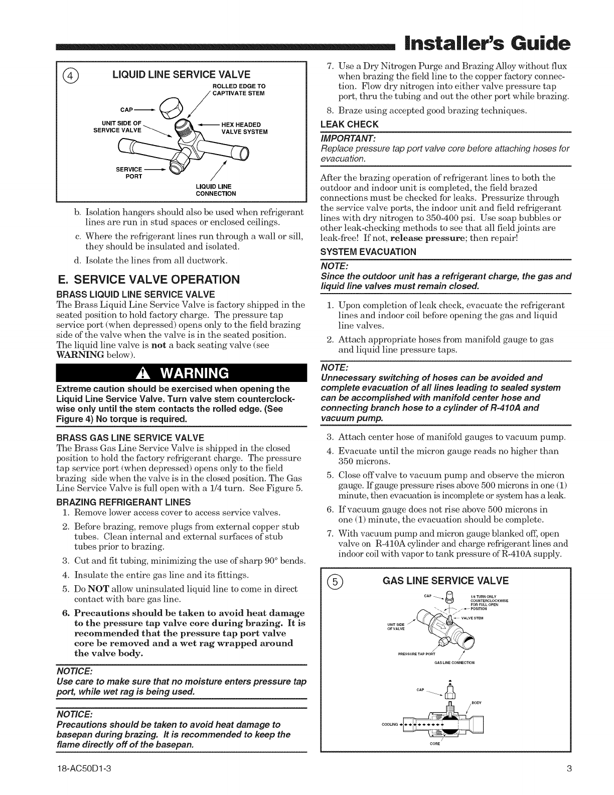
©LIQUID LINE SERVICE VALVE
CAP'_ (_
UNIT SIDE OF f
SERVICE VALVE "_._.._ _
PORT
ROLLED EDGE TO
CAPTIVATE STEM
LIQUID LINE
CONNECTION
b. Isolation hangers should also be used when refrigerant
lines are run in stud spaces or enclosed ceilings.
c. Where the refrigerant lines run through a wall or sill,
they should be insulated and isolated.
d. Isolate the lines from all ductwork.
E. SERVICE VALVE OPERATION
BRASS LIQUID LiNE SERVICE VALVE
The Brass Liquid Line Service Valve is factory shipped in the
seated position to hold factory charge. The pressure tap
service port (when depressed) opens only to the field brazing
side of the valve when the valve is in the seated position.
The liquid line valve is not a back seating valve (see
WARNING below).
Extreme caution should be exercised when opening the
Liquid Line Service Valve. Turn valve stem counterclock-
wise only until the stem contacts the rolled edge. (See
Figure 4) No torque is required.
BRASS GAS LINE SERVICE VALVE
The Brass Gas Line Service Valve is shipped in the closed
position to hold the fhctory refrigerant charge. The pressure
tap service port (when depressed) opens only to the field
brazing side when the valve is in the closed position. The Gas
Line Service Valve is full open with a 1/4 turn. See Figure 5.
BRAZING REFRIGERANT LINES
1. Remove lower access cover to access service valves.
2. Before brazing, remove plugs from external eopper stub
tubes. Clean internal and external surfaces of stub
tubes prior to brazing.
3. Cut and fit tubing, minimizing the use of sharp 90° bends.
4. Insulate the entire gas line and its fittings.
5. Do NOT allow uninsulated liquid line to come in direct
contact with bare gas line.
6. Precautions should be taken to avoid heat damage
to the pressure tap valve core during brazing. It is
recommended that the pressure tap port valve
core be removed and a wet rag wrapped around
the valve body.
NOTICE:
Use care to make sure that no moisture enters pressure tap
port, while wet rag is being used.
NOTICE:
Precautions should be taken to avoid heat damage to
basepan during brazing. It is recommended to keep the
flame directly off of the baeepan.
18-AC50D1-3
7. Use a Dry Nitrogen Purge and Brazing Alloy without flux
when brazing the field line to the copper factory connec-
tion. Flow dry nitrogen into either valve pressure tap
port, thru the tubing and out the other port while brazing.
8. Braze using accepted good brazing techniques.
LEAK CHECK
IMPORTANT:
Replace pressure tap port valve core before attaching hoses for
evacuation.
After the brazing operation of refrigerant lines to both the
outdoor and indoor unit is completed, the field brazed
connections must be checked for leaks. Pressurize through
the service valve ports, the indoor unit and field refrigerant
lines with dry nitrogen to 350-400 psi. Use soap bubbles or
other leak-checking methods to see that all field joints are
leak-free! If not, release pressure; then repair!
SYSTEM EVACUATION
NOTE:
Since the outdoor unit has a refrigerant charge, the gas and
liquid line valves must remain closed.
1. Upon completion of leak check, evacuate the refrigerant
lines and indoor coil before opening the gas and liquid
line valves.
2. Attach appropriate hoses from manifold gauge to gas
and liquid line pressure taps.
NOTE:
Unnecessary switching of hoses can be avoided and
complete evacuation of all lines leading to sealed system
can be accomplished with manifold center hose and
connecting branch hose to a cylinder of R-410A and
vacuum pump.
3.
4.
Attach center hose of manifold gauges to vacuum pump.
Evacuate until the micron gauge reads no higher than
350 microns.
5. Close offvalve to vacuum pump and observe the micron
gauge. If gauge pressure rises above 500 microns in one (1)
minute., then evacuation is incomplete, or system has a leak.
6. If vacuum gauge does not rise above 500 microns in
one (1) minute, the evacuation should be complete.
7. With vacuum pump and micron gauge blanked off; open
valve on R-410A cylinder and charge refrigerant lines and
indoor coil with vapor to tank pressure of R-410A supply.
@GAS LINE SERVICE VALVE
FORFULLOPEN
UNIT SIDE /_STEM
OFVALVE
PRESSURETAPPORT /
GAS LINE CONNECTION
|nsta||er's Guide
NOTE:
DO NOT VENT REFRIGERANT INTO THE ATMOSPHERE.
8. Close valve on R-410A supply cylinder. Close valves on
manifold gauge set and remove refrigerant charging
hoses from liquid and gas pressure tap ports.
NOTE:
A 3/16" Allen wrench is required to open liquid line service
valve. A I/4" Open End or Adjustable wrench is required
to open gas line valve. A 3/4" Open End wrench is required
to take off the valve stem cap.
9. The liquid line shut-offvalve can now be opened. Remove
shut-off valve cap. Fully insert hex wrench into the stem
and backout counte.rclockwise until valve stem just touches
rolled edge (approximately five [5] turns) observing
WARNING statement on page 3. See Figure 4.
10. Replace liquid service pressure tap port cap and valve
stem cap. These caps MUST BE REPLACED to
prevent leaks. Replace valve stem cap and pressure tap
cap finger tight, then tighten an additional 1/6 turn.
11. The gas valve can now be opened. Open the gas valve
by removing the shut-off valve cap and turning the valve
stein 1/4 turn counterclockwise, using 1/4" Open End or
Adjustable wrench. See Figure 5.
12. The gas valve is now open for refrigerant flow. Replace
valve stem cap to prevent leaks. Again, these caps
MUST BE REPLACED to prevent leaks. Replace valve
stem cap and pressure tap cap finger tight, then tighten
an additional 1/6 turn. See Figure 5.
If refrigerant lines are longer than 15 feet and/or a
difihrent size than recommended, it will be necessary to
adjust system refrigerant charge upon completion of
installation. See unit Service Facts.
F. ELECTRICAL CONNECTIONS
When installing or servicing this equipment, ALWAYS
exercise basic safety precautions to avoid the possibility
of electric shock.
1. Power -wiring and grounding of equipment must comply
with local codes.
2. Power supply must agree with equipment nameplate.
3. Install a separate disconnect switch at the outdoor unit.
4. Ground the outdoor unit per local code requirements.
5. Provide flexible electrical conduit whenever vibration
transmission may create a noise problem within the
structure.
6. The use of color coded low voltage wire is recommended
to simplify connections between the outdoor unit, the
thermostat and the indoor unit.
Table 1-- NEC Class II Control Wiring
24 VOLTS
WIRE SIZE MAX. WIRE LENGTH
18 AWG 150 FT
16 AWG 225 FT.
14 AWG 300 FT.
7. Table i defines maximum total length of low voltage
wiring from outdoor unit, to indoor unit, and to thermostat.
8. Mount the indoor thermostat in accordance with instruc-
tion included with the thermostat. Wire per appropriate
hook-up diagram (included in these instructions).
G. COMPRESSOR START UP
After all electrical wiring is complete, SET THE THERMO-
STAT SYSTEM SWITCH IN THE OFF POSITION SO
COMPRESSOR WILL NOT RUN, and apply power by
closing the system main disconnect switch. This will activate
the compressor sump heat (where used). Do not change the
Thermostat System Switch until power has been applied for
one (1) hour. Following this procedure -will prevent potential
compressor overload trip at the initial start-up.
H. OPERATIONAL AND
CHECKOUT PROCEDURES
Final phases of this installation are the unit Operational and
Checkout Procedures which are found in this instruction (see
page 8). To obtain proper performance, all units must be
operated and charge adjustments made in accordance with
procedures found in the Service Facts.
I. ELECTRIC HEATERS
Electric heaters, if used, are to be installed in the air han-
dling device according to the instructions accompanying the
air handler and the heaters.
J. START CONTROL
Some models have quick start components which are factory
installed. For models that do not have factory installed start
components, provisions are made for a field installed start kit
accessory. When adding an accessory, follow the instructions
provided with the kit.
K. OUTDOOR THERMOSTAT
An outdoor thermostat TAYSTAT250A may be field installed.
For data, see wiring diagram attached to unit and instruction
sheet packaged with outdoor thermostat.
L. XL SEACOAST SHIELD
All units are shipped with a black Seacoast Shield attached
to the access panel. Removal of the shield will potentially
shorten the life of the joints in the outdoor coil.
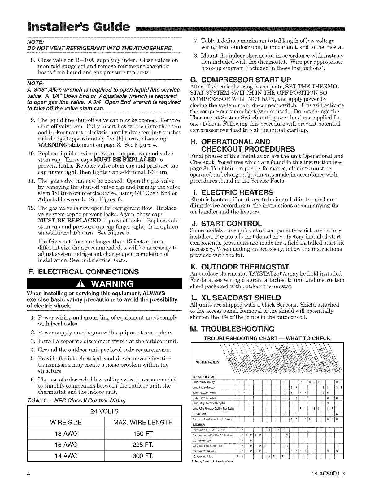
M. TROUBLESHOOTING
TROUBLESHOOTING CHART -- WHAT TO CHECK
SYSTEMFAULTS
Compressor&OD FanDoNotStart
CompressorWIllNotStartButOD FanRuns
P-PrimaryCauses S-SecondaryCauses
4 18-AC50 D 1-3
|nsta|ler's Guide
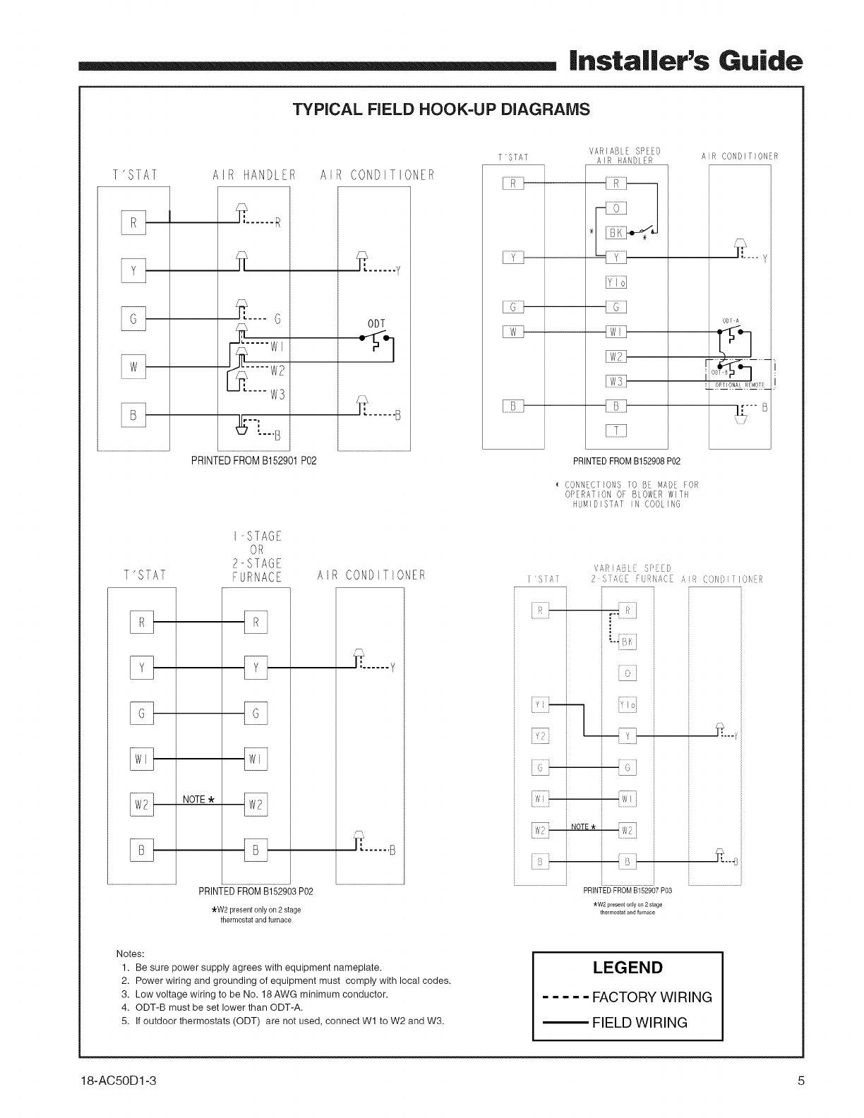
TYPICAL FIELD HOOK=UP DIAGRAMS
1 ' S1AF
T'STAT
E3
A R tIANDL R
_- ..... R
_ .... G
_[--B
PRINTED FROM B152g01 P02
I-STAGE
OR
2-STAGE
FURNACE
NOTE
PRINTEDFROMB152903 P02
"kW2presentonlyon2stage
thermostatandfurnace
A CONDITIONER
...... y
ODT
t:)......B
AIR CONDITIONER
..... y
VARIABLE SPEED
T'STAT AIR HANDLER AIR CONDIr}ONER
"_,'i'... y
ODT A
•.r_i_ _--
I OP leNA R_40T
N'
PRINTED FROM B152908 P02
CONNECTIONS TO BE MADE FOR
OPERATION OF BLOWER WITH
NUMIDISTAT IN COOLING
I 'S J',
V;R _ i : SP '_D
2 S AGE :UF!['£,C Ai_] (()N} i ION R
i _oi '
i NOTE,k l
WP
PRINTED FROM B152907 P03
_rW2 present only on 2 stage
thermostat and furnace
_,"....
Notes:
1. Be sure power supply agrees with equipment nameplate.
2. Power wiring and grounding of equipment must comply with local codes.
3. Low voltage wiring to be No. 18 AWG minimum conductor.
4. ODT-B must be set lower than ODT-A.
5. If outdoor thermostats (ODT) are not used, connect W1 to W2 and W3.
LEGEND
..... FACTORY WIRING
_ FIELD WIRING
18-AC5OD1-3 5
|nsta||er's Guide
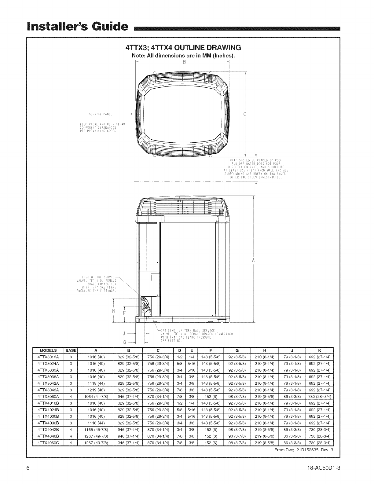
4TTX3; 4TTX4 OUTLINE DRAWING
Note: All dimensions are in MM (Inches).
S[RViCL PANEi ................
EIDCIFiiCAi AND REIRiOERANI
COMPONEN[CiBARANCES
PER PRDVAiilNG CODES
}NI J SOULO B PLAf;ED SO ROD
RU DEE _,A ER DOS NOI POUR
i) REC [v O1'4 JNI ,AND SHO D BE
AI AS 305 {2' FRO_,_ _,Ail #ND AI
SURROUN}I_6 S RUBBERY OK T_,O S DES
OHER [WO $ D_S U RES RICED
MODELS BASE
4TTX3018A 3
4TTX3024A 3
4TTX303OA 3
4TTX3036A 3
4TTX3042A 3
4TTX3048A 3
4TTX3060A 4
4TTX4018B 3
4TTX4024B 3
4TTX4030B 3
4TTX4038B 3
4TTX4042B 4
4TTX4048B 4
4TTX4080C 4
LIQUID LINE SERVICE
VAiV r, "E" ID FEMALE
BRAZE CONB_CTiON
WiTii i/4" SA_ FLARE _\
P_{SSURE rAP FITiiNOS
G
A
1016 (40) 829
1016 (40) 829
1016 (40) 829
1016 (40) 829
1118 (44) 829
1219 (48) 829
1064 (41-7/8) 946
1016 (40) 829
1016 (40) 829
1016 (40) 829
1118 (44) 829
1165 (48-7/8) 946
1267 (49-7/8) 946
1267 (49-7/8) 946
B
(32-5/8)
(32-5/8)
(32-5/8)
(32-5/8)
(32-5/8)
(32-5/8)
(37-1/4)
(32-5/8)
(32-5/8)
(32-5/8)
(32-5/8)
(37-1/4)
(37-1/4)
(37-1/4)
GAS LINE i/4 FURN BALL SERVICE
VALVE, "D" iD FEMALE BRAZED CONNECTION
WiiR I/4 ¸`SAE ELATE P_ESS_RE
rAP EliiiN6
C D EF
758 (29-3/4) 1/2 1/4 143 (5-5/8)
758 (29-3/4) 5/8 5/18 143 (5-5/8)
758 (29-3/4) 3/4 5/18 143 (5-5/8)
758 (29-3/4) 3/4 3/8 143 (5-5/8)
758 (29-3/4) 3/4 3/8 143 (5-5/8)
758 (29-3/4) 7/8 3/8 143 (5-5/8)
870 (34-1/4) 7/8 3/8 152 (8)
758 (29-3/4) 1/2 1/4 143 (5-5/8)
758 (29-3/4) 5/8 5/18 143 (5-5/8)
758 (29-3/4) 3/4 5/18 143 (5-5/8)
758 (29-3/4) 3/4 3/8 143 (5-5/8)
870 (34-1/4) 3/4 3/8 152 (8)
870 (34-1/4) 7/8 3/8 152 (8)
870 (34-1/4) 7/8 3/8 152 (8)
H
210 (8-1/4)
210 (8-1/4)
210 (8-1/4)
210 (8-1/4)
210 (8-1/4)
210 (8-1/4)
219 (8-8/8)
210 (8-1/4)
210 (8-1/4)
210 (8-1/4)
210 (8-1/4)
219 (8-8/8)
219 (8-8/8)
219 (8-8/8)
J
79 (3-1/8)
79 (3-1/8)
79 (3-1/8)
79 (3-1/8)
79 (3-1/8)
79 (3-1/8)
86 (3-3/8)
79 (3-1/8)
79 (3-1/8)
79 (3-1/8)
79 (3-1/8)
86 (3-3/8)
86 (3-3/8)
86 (3-3/8)
K
692 (27-1/4)
692 (27-1/4)
692 (27-1/4)
692 (27-1/4)
692 (27-1/4)
692 (27-1/4)
730 (28--3/4)
692 (27-1/4)
692 (27-1/4)
692 (27-1/4)
692 (27-1/4)
730 (28-3/4)
730 (28-3/4)
730 (28-3/4)
G
92 (3-5/8)
92 (3-8/8)
92 (3-8/8)
92 (3-8/8)
92 (3-8/8)
92 (3-8/8)
98 (3-7/8)
92 (3-8/8)
92 (3-8/8)
92 (3-8/8)
92 (3-8/8)
98 (3-7/8)
98 (3-7/8)
98 (3-7/8)
From Dwg. 21D152635 Rev. 3
6 18-AC5 0D1-3
|nsta||er's Guide
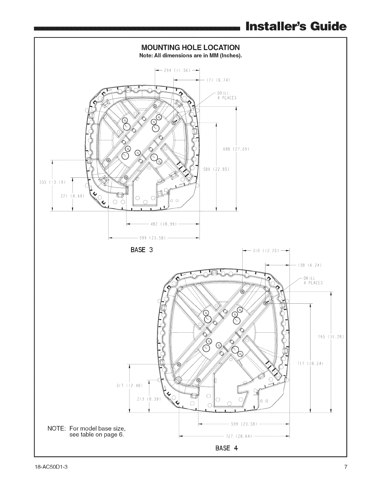
MOUNTING HOLE LOCATION
Note: All dimensions are in IVllVl(Inches).
i7i (6 i/,)
319)
72_ (869
...........................................482 (1899} ......................................
!39'9 (2}%)
BASE 3
C9
;'1;' (28 24)
NOTE: For model base size,
see table on page 6.
5'99 (73 58)
' 2 ( 26 64 )
BASE 4
18-AC50D1-3 7
|nstaller's Guide
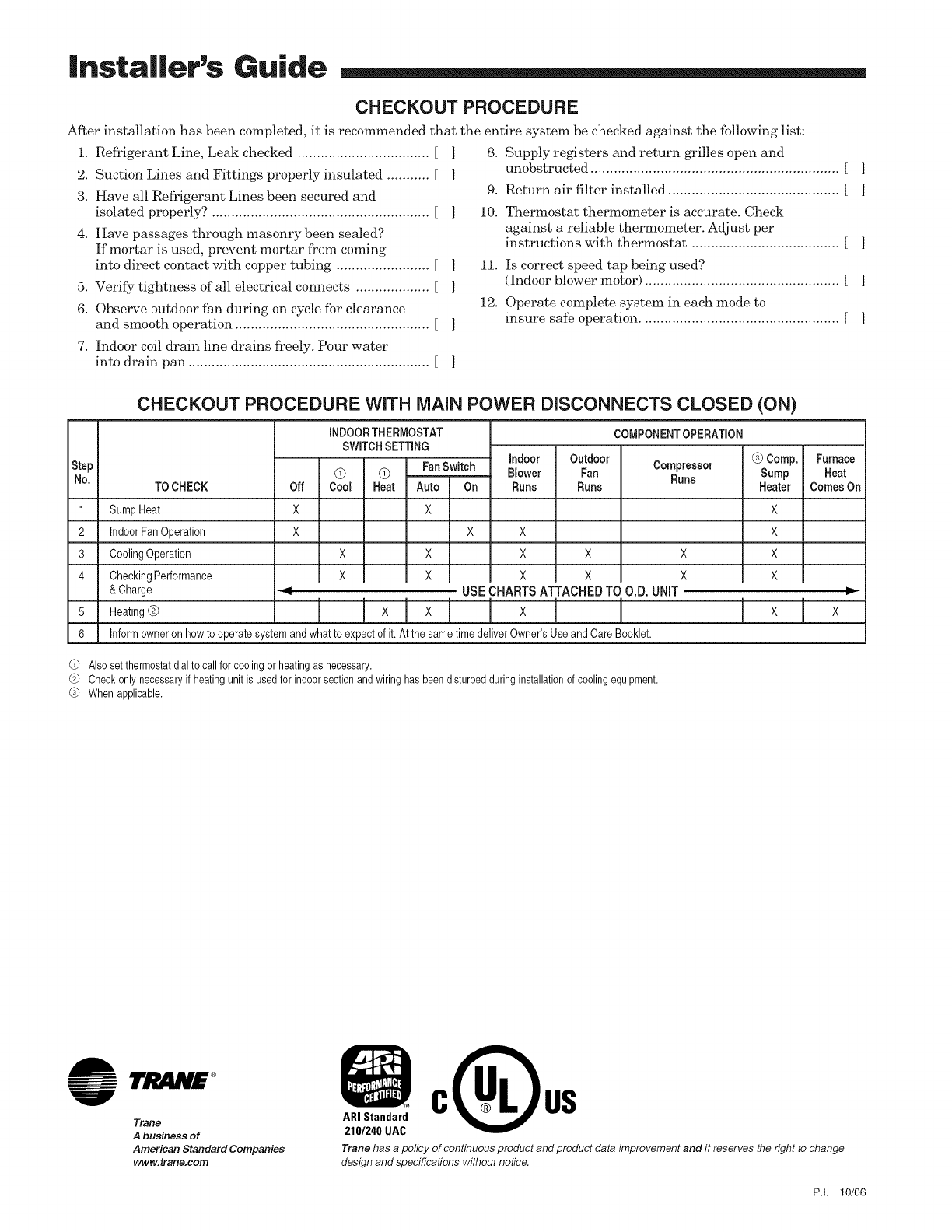
CHECKOUTPROCEDURE
After installation has been completed, it is recommended that the entire system be checked against the following list:
1. Refrigerant Line, Leak checked .................................. [
2. Suction Lines and Fittings properly insulated ........... [
3. Have all Refrigerant Lines been secured and
isolated properly? ........................................................ [
4. Have passages through masonry been sealed?
If mortar is used, prevent mortar from coining
into direct contact with copper tubing ........................ [
5. Verify tightness of all electrical connects ................... [
6. Observe outdoor fan during on cycle for clearance
and smooth operation .................................................. [
]
]
]
]
8. Supply registers and return grilles open and
unobstructed ................................................................ [ ]
9. Return air filter installed ............................................ [ ]
10. Thermostat thermometer is accurate. Check
against a reliable thermometer. Adjust per
instructions with thermostat ...................................... [ ]
11. Is correct speed tap being used?
(Indoor blower motor) .................................................. [ ]
12. Operate complete system in each mode to
insure safe operation ................................................... [ ]
7. Indoor coil drain line drains freely. Pour water
into drain pan .............................................................. [
CHECKOUT PROCEDURE WITH MAiN P(
Step
No. TO CHECK
1 SumpHeat
2 IndoorFan Operation
3 CoolingOperation
4 CheckingPerformance
& Charge
5 Heating@
6
Off
iNDOORTHERMOSTAT
SWITCHSETTING
@ @ FanSwitch
Cool Heat Auto On
X X
)WER DISCONNECTS CLOSED (ON)
COMPONENTOPERATION
Compressor @ Comp. Furnace
Runs Sump Heat
Heater Comes On
X
X
X
X
X
indoor Outdoor
Blower Fan
Runs Runs
x x
x x x x x
x ix I x I x x
USECHARTSATTACHEDTOO.D. UNIT
I Ixlx! Ix ! I
Informowner on howto operatesystem andwhat to expectof it. At the sametimedeliverOwner'sUseand Care Booklet.
!
@Also set thermostat dial to call for cooling or heating as necessary.
@ Check only necessary if heating unit is used for indoor section and wiring has been disturbed during installation of cooling equipment,
@ When applicable.
1r'JMNE
Trane
A business of
American Standard Companies
www.trane.com
,0°0°,
210/248UAC
Trane has a policy of continuous product and product data improvement and it reserves the right to change
design and specifications without notice.
P.I. 10/06
