TRANE Air Handler (indoor Blower&evap) Manual L0905031
User Manual: TRANE TRANE Air Handler (indoor blower&evap) Manual TRANE Air Handler (indoor blower&evap) Owner's Manual, TRANE Air Handler (indoor blower&evap) installation guides
Open the PDF directly: View PDF 
Page Count: 24
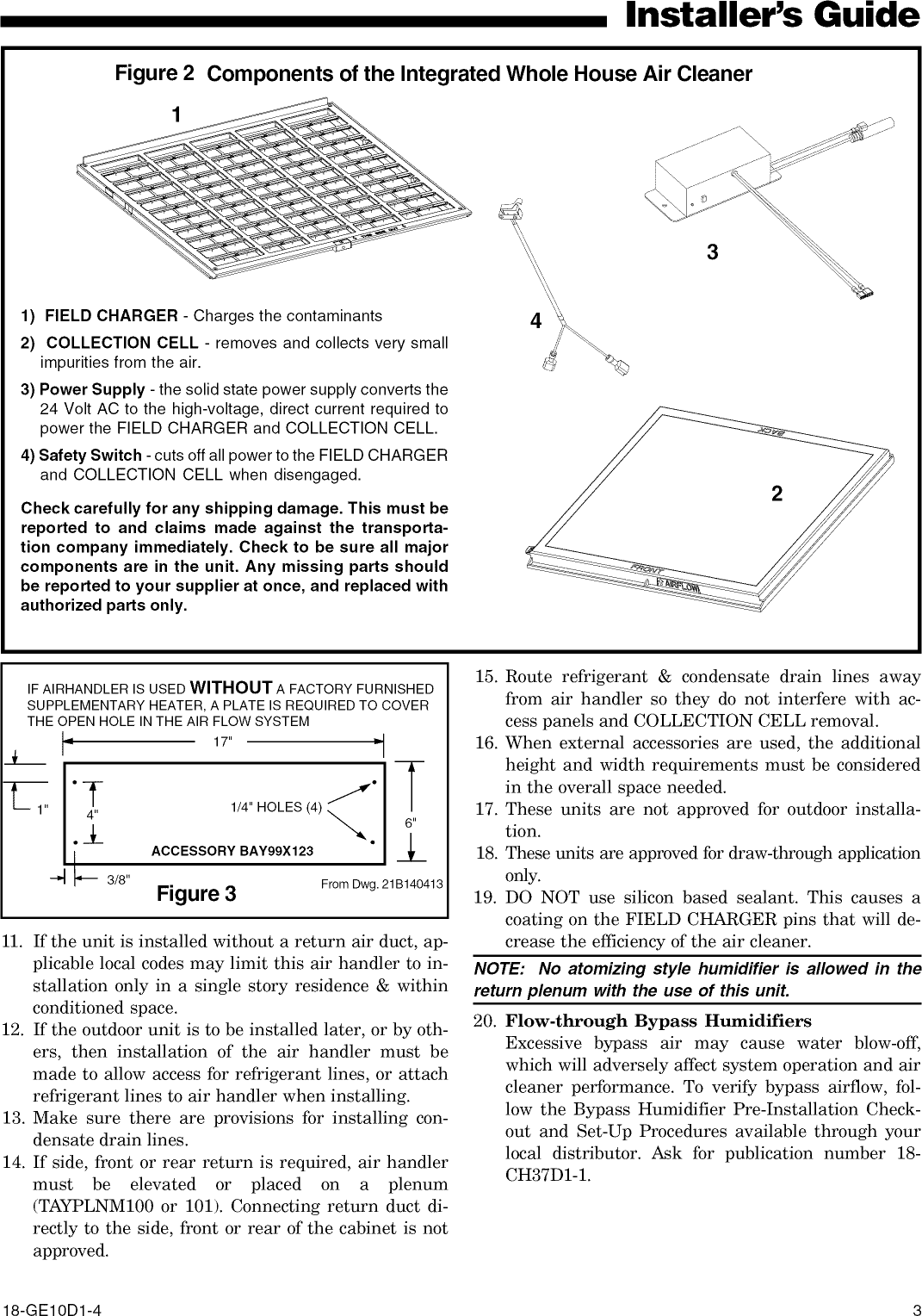
![Installer's GuideThese air handlers are suitable for installation in acloset, alcove or utility room with free, non-ducted, airreturn, using the area space as a return air plenum.With ducted supply air, if the minimum clearances tocombustible materials and service access are observed,the above installations are suitable.This area may also be used for other purposes, includ-ing an electric hot water heater- but in no case shalla fossil fuel device be installed and!or operated inthe same closet, alcove or utility room.In addition, these air handlers are suitable for installa-tion in an attic, garage or crawl space with ducted sup-ply and return air.This equipment has been evaluated in accordance withthe U.S. Department of Housing and Urban Develop-ment code. Air handler is Suitable for mobile home/manufactured housing use. Unit is also approved formodular homes.For proper installation the following items must be con-sidered:1. If adequate power is available and correct accordingto nameplate specifications.2. Prior to unit installation, a heavy gauge steelplate is attached to the bottom of the unit forprotection during shipping and handling.Leave this plate in place until the unit isready to be connected to ductwork.3. Insulate all ducts, particularly if unit is located out-side of the conditioned space.4. Pursuant to Florida Building Code 13-610.2.A.2.1,this unit meets the criteria for a factory sealedair handler.5. To ensure maximum efficiency and system perfor-mance, the existing supply and return duct systemstatic pressures must not exceed the total availablestatic pressure of the air handler. Reference ACCAManual D, Manual S and Manual RS along with theair handler Product Data and Service Facts for addi-tional information.6. It is recommended that the outline drawing be stud-ied and dimensions properly noted and checkedagainst selected installation site. By noting in ad-vance which knockouts are to be used, proper clear-ance allowances can be made for installation and fu-ture service.7. Allow a minimum of 21 inches clearance in frontof the air handler to permit removal of COLLEC-TION CELL and FIELD CHARGER.8. Do not install air handler where air cleaner can beexposed to UV light.9. When the air handler with supplementary heater isto be installed in the downflow position on combus-tible flooring an accessory sub-base (TAYBASE101for 2/4TEE3D31, TAYBASE100 for 2/4TEE3D37,TAYBASE102 for 2/4TEE3D40-65) must be used.See Figure 1.10. If supplementary heat is to be added, power supplymust be sut_cient to carry the load. In addition,minimum airflow settings, unit and duct clearancesto combustible material must be maintained asstated on the air handler rating nameplate.[o lji o]For air handlers not equipped with a factory installedelectric heater, a field installed heater is available fromTrane. Only heaters built by Trane are approved for usein the air handler. These heaters have been designedand tested in accordance with UL standards to providesafe and reliable operation. A list of approved heatersis provided on the air handler rating nameplate. Heat-ers that are not factory approved could cause damageand are not covered under equipment warranty.NOTE: If air handler is used WITHOUT a supplemen-tary electric heater, a sheetmetal plate is required tocover the open hole in the airflow system. See Figure3.Figure 1 AIR HANDLER SUB-BASEFLOOR OPENING - SIZEMODEL NO. A BTAYBASE100 23-3/4 14-13/16TAYBASE101 21-3/4 14-13/16TAYBASE102 26-3/4 14-13/16........ AINAILS_._AOER'" *_I" _" _ ANY¢OMSUS_SBLE_ATEm_L© 2008Trane 18-G E10D1-4](https://usermanual.wiki/TRANE/L0905031.1135706890-User-Guide-Page-2.png)