TRANE Air Handler (indoor Blower&evap) Manual L0905031
User Manual: TRANE TRANE Air Handler (indoor blower&evap) Manual TRANE Air Handler (indoor blower&evap) Owner's Manual, TRANE Air Handler (indoor blower&evap) installation guides
Open the PDF directly: View PDF ![]() .
.
Page Count: 24
8-GE0D-5
Convertible Variable Speed - Air Handlers 2 1/2 - 5 Ton
with Integrated Whole House Air Cleaner
2/4TEE3D31A1000A, 2/4TEE3D37A1000A, 2/4TEE3D40A1000A,
2/4TEE3D49A1000A, 2/4TEE3D65A1000A
ALL phases of this installation must comply with NATIONAL, STATE AND LOCAL CODES
IMPORTANT -- This Document is customer property and is to remain with this unit. Please return to service information
pack upon completion of work.
A. GENERAL INFORMATION
THIS INFORMATION IS FOR USE BY INDIVIDUALS
HAVING ADEQUATE BACKGROUNDS OF ELECTRICAL
AND MECHANICAL EXPERIENCE. ANY ATTEMPT TO
REPAIR A CENTRAL AIR CONDITIONING PRODUCT
MAY RESULT IN PERSONAL INJURY AND/OR PROP-
ERTY DAMAGE. THE MANUFACTURER OR SELLER
CANNOT BE RESPONSIBLE FOR THE INTERPRETA-
TION OF THIS INFORMATION, NOR CAN IT ASSUME
ANY LIABILITY IN CONNECTION WITH ITS USE.
To prevent shortening its service life, the air handler
should not be used during the finishing phases of con-
struction. The low return air temperatures can lead to
the formation of condensate. Condensate in the pres-
ence of chlorides and fluorides from paint, varnish,
stains, adhesives, cleaning compounds, and cement
creates a corrosive condition which may cause rapid
deterioration of the cabinet and internal components.
This unit is equipped with an integrated high efficiency
Whole House Air Cleaner. Careful consideration must
be taken in the installation process to avoid personal in-
jury or equipment damage. These instructions do not
cover all variations in systems or provide for every pos-
sible contingency. Should further information be desired
or particular problems arise which are not covered suffi-
ciently by this manual, contact your local distributor or
the manufacturer as listed on the air handler name-
plate.
These Air Handlers are shipped from the factory in the
upflow or horizontal right configuration and are fully
convertible to downflow or horizontal left. Refer to Sec-
tion C beginning on page 4 for additional information.
INSPECTION
Check carefully for any shipping damage. This must be
reported to and claims made against the transportation
company immediately. Check to be sure all major com-
ponents are in the unit. Any missing parts should be re-
ported to your supplier at once, and replaced with au-
thorized parts only.
CONTENTS
General Information ........................................... .._ _
Installation Limitations & Recommendations
Two Piece Cabinet Disassembly
Unit Installation ...................................................
Vertical Upflow ....................................................................
Vertical Downflow ................................................................
Horizontal Left ..................................................................... i:
Horizontal Right
Duct Connection
Refrigerant Piping ..............................................
Brazing to Evaporator Section ........................
Condensate Drain Piping ...................................
Electrical-Wiring ................................................
Airflow Adjustment ..............................................
Maintenance Check Out Procedure ...............
Cleaning the COLLECTION CELL ................. _i_
Cleaning the FIELD CHARGER ....................... ..........
Hook Up Diagrams ..............................................
Outline Drawings ................................................
Checkout Procedures .........................................
INSTALLATION LIMITATIONS& RECOMMENDATIONS
The general location of the air handler is normally se-
lected by the architect, contractor and/or home owner
for the most effective application and satisfaction.
NOTE: Condensation may occur on the surface of the
air handler when installed in an unconditioned loca-
tion. When units are installed in unconditioned spaces,
verify that all electrical and refrigerant line penetrations
on the air handler are sealed completely.
Installer's Guide
These air handlers are suitable for installation in a
closet, alcove or utility room with free, non-ducted, air
return, using the area space as a return air plenum.
With ducted supply air, if the minimum clearances to
combustible materials and service access are observed,
the above installations are suitable.
This area may also be used for other purposes, includ-
ing an electric hot water heater- but in no case shall
a fossil fuel device be installed and!or operated in
the same closet, alcove or utility room.
In addition, these air handlers are suitable for installa-
tion in an attic, garage or crawl space with ducted sup-
ply and return air.
This equipment has been evaluated in accordance with
the U.S. Department of Housing and Urban Develop-
ment code. Air handler is Suitable for mobile home/
manufactured housing use. Unit is also approved for
modular homes.
For proper installation the following items must be con-
sidered:
1. If adequate power is available and correct according
to nameplate specifications.
2. Prior to unit installation, a heavy gauge steel
plate is attached to the bottom of the unit for
protection during shipping and handling.
Leave this plate in place until the unit is
ready to be connected to ductwork.
3. Insulate all ducts, particularly if unit is located out-
side of the conditioned space.
4. Pursuant to Florida Building Code 13-610.2.A.2.1,
this unit meets the criteria for a factory sealed
air handler.
5. To ensure maximum efficiency and system perfor-
mance, the existing supply and return duct system
static pressures must not exceed the total available
static pressure of the air handler. Reference ACCA
Manual D, Manual S and Manual RS along with the
air handler Product Data and Service Facts for addi-
tional information.
6. It is recommended that the outline drawing be stud-
ied and dimensions properly noted and checked
against selected installation site. By noting in ad-
vance which knockouts are to be used, proper clear-
ance allowances can be made for installation and fu-
ture service.
7. Allow a minimum of 21 inches clearance in front
of the air handler to permit removal of COLLEC-
TION CELL and FIELD CHARGER.
8. Do not install air handler where air cleaner can be
exposed to UV light.
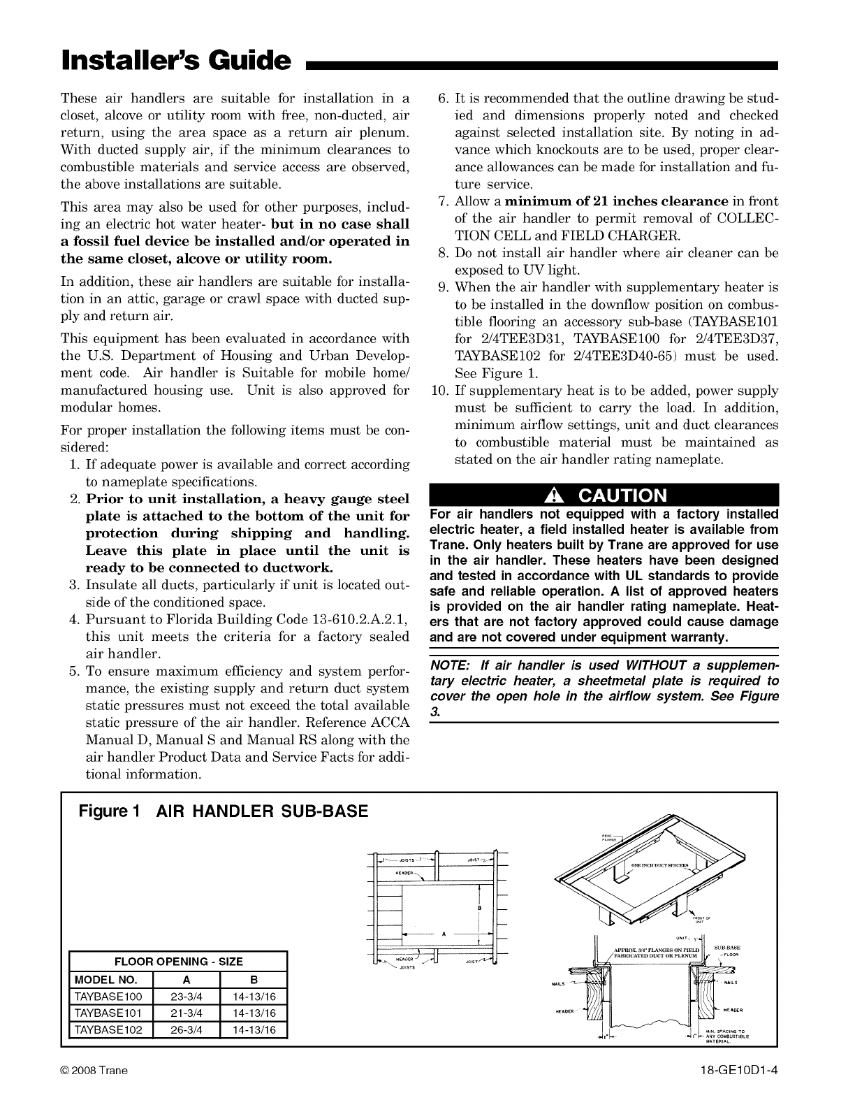
9. When the air handler with supplementary heater is
to be installed in the downflow position on combus-
tible flooring an accessory sub-base (TAYBASE101
for 2/4TEE3D31, TAYBASE100 for 2/4TEE3D37,
TAYBASE102 for 2/4TEE3D40-65) must be used.
See Figure 1.
10. If supplementary heat is to be added, power supply
must be sut_cient to carry the load. In addition,
minimum airflow settings, unit and duct clearances
to combustible material must be maintained as
stated on the air handler rating nameplate.
[o lji o]
For air handlers not equipped with a factory installed
electric heater, a field installed heater is available from
Trane. Only heaters built by Trane are approved for use
in the air handler. These heaters have been designed
and tested in accordance with UL standards to provide
safe and reliable operation. A list of approved heaters
is provided on the air handler rating nameplate. Heat-
ers that are not factory approved could cause damage
and are not covered under equipment warranty.
NOTE: If air handler is used WITHOUT a supplemen-
tary electric heater, a sheetmetal plate is required to
cover the open hole in the airflow system. See Figure
3.
Figure 1 AIR HANDLER SUB-BASE
FLOOR OPENING - SIZE
MODEL NO. A B
TAYBASE100 23-3/4 14-13/16
TAYBASE101 21-3/4 14-13/16
TAYBASE102 26-3/4 14-13/16
........ A
I
NAILS_
._AOER'" *_
I" _" _ ANY¢OMSUS_SBLE
_ATEm_L
© 2008Trane 18-G E10D1-4

Installer's Guide
Figure 2 Components of the Integrated Whole House Air Cleaner
3
1) FIELD CHARGER - Charges the contaminants
2) COLLECTION CELL - removes and collects very small
impurities from the air.
3) Power Supply - the solid state power supply converts the
24 Volt AC to the high-voltage, direct current required to
power the FIELD CHARGER and COLLECTION CELL.
4) Safety Switch - cuts off all power to the FIELD CHARGER
and COLLECTION CELL when disengaged.
Check carefully for any shipping damage. This must be
reported to and claims made against the transporta-
tion company immediately. Check to be sure all major
components are in the unit. Any missing parts should
be reported to your supplier at once, and replaced with
authorized parts only.
4
L
IF AIRHANDLER IS USED WITHOUT A FACTORY FURNISHED
SUPPLEMENTARY HEATER, A PLATE IS REQUIRED TO COVER
THE OPEN HOLE IN THE AIR FLOW SYSTEM
4 17" ='{
I
"T
4"
.±
_-- 3/8"
(4) J"
1/4" HOLES
=
ACCESSORY BAY99X123
7
Figure 3 From Dwg. 21B140413
11. If the unit is installed without a return air duct, ap-
plicable local codes may limit this air handler to in-
stallation only in a single story residence & within
conditioned space.
12. If the outdoor unit is to be installed later, or by oth-
ers, then installation of the air handler must be
made to allow access for refrigerant lines, or attach
refrigerant lines to air handler when installing.
13. Make sure there are provisions for installing con-
densate drain lines.
14. If side, front or rear return is required, air handler
must be elevated or placed on a plenum
(TAYPLNM100 or 101). Connecting return duet di-
rectly to the side, front or rear of the cabinet is not
approved.
15. Route refrigerant & condensate drain lines away
from air handler so they do not interfere with ac-
cess panels and COLLECTION CELL removal.
16. When external accessories are used, the additional
height and width requirements must be considered
in the overall space needed.
17. These units are not approved for outdoor installa-
tion.
18. These units are approved for draw-through application
only.
19. DO NOT use silicon based sealant. This causes a
coating on the FIELD CHARGER pins that will de-
crease the efficiency of the air cleaner.
NOTE: No atomizing style humidifier is allowed in the
return plenum with the use of this unit.
20. Flow-through Bypass Humidifiers
Excessive bypass air may cause water blow-off,
which will adversely affect system operation and air
cleaner performance. To verify bypass airflow, fol-
low the Bypass Humidifier Pre-Installation Cheek-
out and Set-Up Procedures available through your
local distributor. Ask for publication number 18-
CH37D1-1.
18-GE10D1-4 3

Installer's Guide
Steam and Flow-through Fan Power Duct-
mounted Humidifiers
Follow the humidifier installation instructions.
These should only be installed on the supply air
side of the system.
Other Duct Mounted Humidifiers are Not rec-
ommended for installation with the air
cleaner.
21. Unit installation must include either a return air
duet or grill that prevents accidental access to pins.
For upflow open air intake applications that do not
have a grill or return air duet, installation will re-
quire the use of either BAYPLNM120, TASB215,
TA_qB235, or TA_qB260 depending on cabinet size.
TA_qB accessories can be purchaed from:
Miami Tech Inc.
3611 NW 74 Street
Miami, Florida 33147
Phone: 800-339-2290
Fax: 305-693-6152
www.miamitech.com
TA_qB215 for use with 21.5" cabinets 2/4TEE3D31
TANB235 for use with 23.5" cabinets 2/4TEE3D37
TA_qB260 for use with 26.0" cabinets 2/4TEE3D40,49,
and 65
22. A PRE-FILTER is not required to be installed with
the air handler containing a Whole House Air
Cleaner. If the use of a PRE-FILTER is desired, it
must be installed at least 6" away from the Whole
House Air Cleaner.
B. TWO PIECE CABINET DISASSEMBLY
(OPTIONAL)
NOTE: For easier installation into tight areas, the 4
and 5ton air handlers can be disassembled and reas-
sembled after moved to an attic or other space.
Steps for disassembly and reassembly (See Figures 4
and 5)
1. Disconnect wiring.
2. Remove center bracket.
3. Remove blower assembly.
4. Remove coil.
5. Cut foil tape - minimum 3" foil tape.
6. Remove top 8 screws. See Figure 3.
7. Lift upper section.
8. Set air handler in place.
9. Attach screws - insure gaskets are aligned
along flange.
10. Use foil tape to seal - use minimum 3" foil tape.
11. Insert coil.
12. Reinstall blower assembly.
13. Reinstall center bracket.
14. Reconnect wiring.
NOTE: In Downflow, remove coil before blower by
reversing steps 4 and 5.
SCREWS 5-8
LOCATED ON
LEFT SIDE _._
Figure 4 Closeup of Spear Locations
Figure 5 2 Piece Wrapper Spear
I
!
//
o/
/
C. UNIT INSTALLATION
UPFLOW
When unit is installed in non-ducted appfications,
BAYPLNM120 must be used.
a. Before installing unit, remove thumbscrews to
the filter panel. Carefully remove the COLLEC-
TION CELL by grasping the leading edge of the
frame. See Figure 6. Set aside in a safe place un-
til the unit is set in place and ready to start up.
b. Use a 5/16" nutdriver to remove the screws hold-
ing the FIELD CHARGER retainer and take out
both. Slightly lift the FIELD CHARGER and care-
fully remove. Set aside in a safe place until the
unit is set in place and ready to start up. See Fig-
ures 7 and 8.
e. Position unit to remove the bottom protector
plate by laying the unit on its back. Use a flat
blade screwdriver between the protector plate
and the unit to pry apart. See Figure 9. Gently
pull the plate towards the front of the unit to re-
move.
4 18-GE10D1-5

Installer's Guide
d. For maximum efficiency, the horizontal drip
tray should be removed. See Figures 10, 11 and
12. Tray removal requires that the coil be re-
moved by sliding the coil out on the coil channel
supports. For the TEE3D40-65 units, there is a
coil support tab at the top of the coil connected to
the case that must be removed first. Remove 1
inch insulation strip covering the lip of the drip
tray. The tray is detached by removing the two
screws at the drain pan. Remove the two screws
holding the two brackets at the top of the coil.
Remove drip tray by gently breaking the seal be-
tween the drip tray and drain pan.
e. Remove the factory installed baffle assembly
from the apex of the coil by using a 5/16"
nutdriver to remove the screws. Replace this
baffle with the factory supplied narrow coil baffle
using the screws removed previously. See Figure
15. Reinstall coil assembly.
When installing the narrow coil baffle, make sure to
align the baffle up with the holes so NOT to puncture
the coil tubing.
f. Position unit on Pedestal or other suitable foun-
dation. If Pedestal is not used, a frame strong
enough to support the total weight must be pro-
vided. Provide a minimum height of 14 inches for
proper unrestricted airflow. In open return ap-
plications, installation requires a BAYPLNM or
TA_B stand.
g. If a return air duct is connected to the air han-
dler, it must be the same dimensions as shown in
the outline drawing on page 20.
h. On units with sheetmetal returns: Return
plenum must be flanged. Sheetmetal screws
must be 1/2" in length or shorter. Self-tap-
ping screws are supplied with unit in ac-
cessory pack. See Figure 17.
i. No sheetmetal screws may be used to at-
tach return duct work on the side of the
unit.
j. Pedestal and unit should be isolated from the
foundation using a suitable isolating material.
k. Openings where field wiring enters the
cabinet must be completely sealed. Location
of power entry is shown on the Outline Drawing.
Use 2.5" clear stickers provided to seal all unused
electrical knockouts. See Figure 16.
1. After ductwork connections are made, seal air-
tight and per Local codes.
m. Install FIELD CHARGER as shown in Figure 18
(Upflow). Ionizing pins must face downward (into
the return air stream) and electrical contacts
must be on the left side of the unit.
n. Reinstall FIELD CHARGER retainer bracket.
o. Install COLLECTION CELL as shown in Figure
18 (Upflow) so that electrical contacts and actua-
tor tab are on the left side of the unit.
p. Install filter panel with thumbscrews.
DOWNFLOW
a. Before installing unit, remove thumbscrews to
the filter panel. Carefully remove the COLLEC-
TION CELL by grasping the leading edge of the
frame. See Figure 6. Set aside in a safe place un-
til the unit is set in place and ready to start up.
b. Use a 5/16" nutdriver to remove the screw in the
FIELD CHARGER retainer and take out both.
Slightly lift the FIELD CHARGER and carefully
remove. Set aside in a safe place until the unit is
set in place and ready to start up. See Figures 7
and 8.
c. Position unit to remove the bottom protector
plate by laying the unit on its back. Use a flat
blade screwdriver between the protector plate
and the unit to pry apart. See Figure 9. Gently
pull the plate towards the front of the unit to re-
move.
d. For maximum efficiency, the horizontal drip
tray should be removed. See Figures 10, 11 and
12. Tray removal requires that the coil be re-
moved by sliding the coil out on the coil channel
supports. For the TEE3D40-65 units, there is a
coil support tab at the top of the coil connected to
the case that must be removed first. Remove 1
inch insulation strip covering the lip of the drip
tray. The tray is detached by removing the two
screws at the drain pan and the two screws hold-
ing the two brackets at the top of the coil. Re-
move drip tray by gently breaking the seal be-
tween the drip tray and drain pan.
e. Remove the factory installed baffle assembly
from the apex of the coil by using a 5/16"
nutdriver to remove the screw. Replace this
baffle with the factory supplied narrow coil baffle
using the screws removed previously. See Figure
15.
When installing the narrow coil baffle, make sure to
align the baffle up with the holes so NOT to puncture
the coil tubing.
NOTE: Installation of the downflow baffle kit included
with unit is required on downflow applications. See
Figure 14.
f. Remove front shield by removing screws on right
side. Make sure to reinstall front shield after
baffle changes. See Figure 14.
g. Detach the coil from the drain pan by removing 4
screws as shown in Figure 14.
18-GE10D1-5 5

Installer's Guide
Figure 6 COLLECTION CELL Removal
o
Figure 7 FIELD CHARGER Retainer Bracket Removal
Figure 9 Protector Plate Removal
/
Figure 8 FIELD CHARGER Removal Figure 10 Drip Pan Foam Removal
18-GE10D1-5
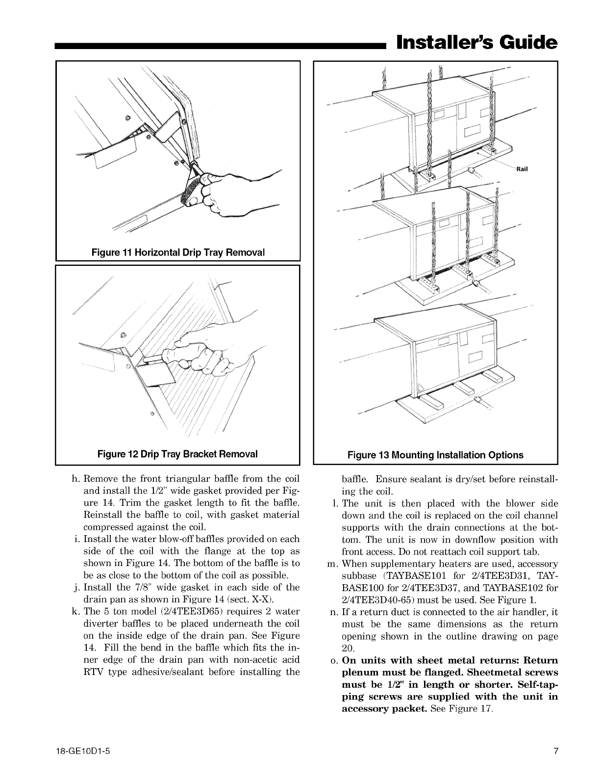
Figure 11 Horizontal Drip Tray Removal
\
,,f
Figure 12 Drip Tray Bracket Removal
h. Remove the front triangular baffle from the coil
and install the 1/2" wide gasket provided per Fig-
ure 14. Trim the gasket length to fit the baffle.
Reinstall the baffle to coil, with gasket material
compressed against the coil.
i. Install the water blow-offbaffles provided on each
side of the coil with the flange at the top as
shown in Figure 14. The bottom of the baffle is to
be as close to the bottom of the coil as possible.
j. Install the 7/8" wide gasket in each side of the
drain pan as shown in Figure 14 (sect. X-X).
k. The 5 ton model (2/4TEE3D65) requires 2 water
diverter baffles to be placed underneath the coil
on the inside edge of the drain pan. See Figure
14. Fill the bend in the baffle which fits the in-
ner edge of the drain pan with non-acetic acid
RTV type adhesive/sealant before installing the
Installer's Guide
......... Rail
Figure 13 Mounting Installation Options
baffle. Ensure sealant is dry/set before reinstall-
ing the coil.
1. The unit is then placed with the blower side
down and the coil is replaced on the coil channel
supports with the drain connections at the bot-
tom. The unit is now in downflow position with
front access. Do not reattach coil support tab.
m. When supplementary heaters are used, accessory
subbase (TAYBASE101 for 2/4TEE3D31, TAY-
BASE100 for 2/4TEE3D37, and TAYBASE102 for
2/4TEE3D40-65) must be used. See Figure 1.
n. If a return duet is connected to the air handler, it
must be the same dimensions as the return
opening shown in the outline drawing on page
20.
o. On units with sheet metal returns: Return
plenum must be flanged. Sheetmetal screws
must be 1/2" in length or shorter. Self-tap-
ping screws are supplied with the unit in
accessory packet. See Figure 17.
18-GE10D1-5 7

Installer's Guide
SCREWS TO
REMOVE COIL
7/8"
7/8"
Figure 14 DOWNFLOW BAFFLE KIT
DISCARD
TRAY
TRIANGULAR
BAFFLE
FRONT
SHIELD
SECT. X-X
(TYP. BOTH SIDES)
1/2" GASKET
INSIDE SURFACE
OF BAFFLE SCREWS TO
REMOVE COIL
p.
q.
r.
S.
t.
U.
WATER _.
BLOW-OFF--,. /o°_°_°/ _,,W,ATE R,_, _o°_
BAFFLES "X_ /2_OoO/_ v LH,L,..H_... _oOoOo\,._
Ooo _
ATTACH WITH '_/L'./_o rLonEl_) _o_o_,
2 SCREWS [ZZ_ """ /'i_/_._
EACH SIDE I ,, -... ,/ ,- ,J,J
_LL WITH SEALANT
No sheetmetal screws may be used to at-
tach return ductwork on the side of the
unit.
Install FIELD CHARGER as shown in Figure 18
(Downflow). Ionizing pins must face upward (into
the return air stream) and electrical contacts
must be on the right side of the unit.
Reinstall FIELD CHARGER retainer bracket.
Install COLLECTION CELL as shown in Figure
18 (Downflow) so that electrical contacts and ac-
tuator tab are on the right side of the unit.
Install filter panel with thumbscrews.
Openings where field wiring enters the
cabinet must be completely sealed. Location
of power entry is shown on the outline drawing.
For Maximum Efficiency
on Horizontal Left_
Upflow and Downflow
Remove Replace
and with
Discard Narrow
Baffle
Figure 15
Use 2.5" clear stickers provided to seal all unused
electrical knockouts. See Figure 16.
v. After ductwork connections are made, seal air-
tight and per Local codes.
HORIZONTAL LEFT
8 18-GE10D1-5

f
/
Figure 16
Figure 17 Flange Attachment
a. Before installing unit, remove thumbscrews to
the filter panel. Carefully remove the COLLEC-
TION CELL by grasping the leading edge of the
frame. See Figure 6. Set aside in a safe place un-
til the unit is set in place and ready to start up.
b. Use a 5/16" nutdriver to remove the screws in
the FIELD CHARGER retainer and take out
both. Slightly lift the FIELD CHARGER and care-
fully remove. Set aside in a safe place until the
unit is set in place and ready to start up. See Fig-
ures 7 and 8.
C.
d.
e.
Installer's Guide
Position unit to remove the bottom protector
plate by laying the unit on its back. Use a fiat
blade screwdriver between the protector plate
and the unit to pry apart. See Figure 9. Gently
pull the plate towards the front of the unit to re-
move.
To convert the unit to horizontal left, front ac-
cess, slide the coil out on the coil channel sup-
ports and rotate the complete coil 180 degrees.
For maximum efficiency, remove the factory
installed baffle assembly from the apex of the coil
by using a 5/16" nutdriver to remove the hex
head screws. For the TEE3D40-65 units, there is
a coil support tab at the top of the coil connected
to the case must be removed first. Replace this
baffle with the factory supplied narrow coil baffle
using the screws removed previously. See Figure
15.
When installing the narrow coil baffle, make sure to
align the baffle up with the holes so NOT to puncture
the coil tubing.
f. The coil is then inserted back into the cabinet on
the opposite side coil channel supports. The unit
is now horizontal left with front access. Do not
reattach coil support tab.
g. If the unit is suspended, it must be supported
from the bottom near both ends as well as the
middle to prevent sagging. The service access
must remain unobstructed. If the unit is sup-
ported along the length of the front and back
with rails, the air handler only needs to be sus-
pended at both ends. See Figure 13.
If the unit is not suspended it must be supported
as mentioned above and isolated carefully to pre-
vent sound transmission. Vibration isolators (put-
chased locally) must be placed under the unit.
h. It is always recommended that an auxiliary drain
pan be installed under a horizontal air handler
(See Condensate Piping) to prevent possible dam-
age to ceilings.
i. Isolate the auxiliary drain pan from the unit or
from the structure.
j. Connect the auxiliary drain line to a separate
drain line (no trap is needed in this line) and ter-
minate according to National and Local codes.
k. If a return duet is connected to the air handler, it
must be the same dimensions as the return
opening shown in the outline drawing on page
20.
.On units with sheetmetal returns: Return
plenum must be flanged. Sheetmetal screws
18-GE10D1-5 9

Installer's Guide
m.
n.
must be 1/2" in length or shorter. Self-tap-
ping screws are supplied with the unit in
accessory packet. See Figure 17.
No sheetmetal screws may be used to at-
tach return ductwork on the side of the
unit.
Install FIELD CHARGER as shown in Figure 19
(Horitzontal Left). Ionizing pins must point into
the return air stream (right). Electrical contacts
will now be on the bottom of the FIELD
CHARGER.
o. Reinstall FIELD CHARGER retainer bracket.
p. Install COLLECTION CELL as shown in Figure
19 (Horizontal Left) so that electrical contacts
and actuator tab are on the bottom of the COL-
LECTION CELL.
q. Install filter panel with thumbscrews.
r. Openings where field wiring enters the
cabinet must be completely sealed. Location
of power entry is shown on the outline drawing.
Use 2.5" clear stickers provided to seal all unused
electrical knockouts. See Figure 16.
n. After ductwork connections are made, seal air-
tight and per Local codes.
HORIZONTAL RIGHT
a. Before installing unit, remove thumbscrews to
the flter panel. Carefully remove the COLLEC-
TION CELL by grasping the leading edge of the
frame. See Figure 6. Set aside in a safe place un-
til the unit is set in place and ready to start up.
b. Use a 5/16" nutdriver to remove the screws hold-
ing the FIELD CHARGER retainer and take out
both. Slightly lift the FIELD CHARGER and care-
fully remove. Set aside in a safe place until the
unit is set in place and ready to start up. See Fig-
ures 7 and 8.
C. Position unit to remove the bottom protector
plate by laying the unit on its back. Use a flat
blade screwdriver between the protector plate
and the unit to pry apart. See Figure 9. Gently
pull the plate towards the front of the unit to re-
move.
d.
e.
Unit is shipped from the factory in the upflow or
horizontal right configuration. Unit conversion is
not required.
If the unit is suspended, it must be supported
from the bottom near both ends as well as the
middle to prevent sagging. The service access
must remain unobstructed. If the unit is sup-
g.
h.
ported along the length of the front and back, the
air handler only needs to be suspended at both
ends. See Figure 13.
If the unit is not suspended it must be supported
as mentioned above and isolated carefully to pre-
vent sound transmission. Vibration isolators (put-
chased locally) must be placed under the unit.
It is always recommended that an auxiliary drain
pan be installed under a horizontal air handler
(See Condensate Drain Piping) to prevent pos-
sible damage to ceilings.
Isolate the auxiliary drain pan from the unit or
from the structure.
Connect the auxiliary drain line to a separate
drain line (no trap is needed in this line) and ter-
minate according to National and Local codes.
If a return duct is connected to the air handler, it
must be the same dimensions as the return
opening shown in the outline drawing on page
20.
j. On units with sheetmetal returns: Return
plenum must be flanged. Sheetmetal screws
must be 1/2" in length or shorter. Self-tap-
ping screws are supplied with the unit in
accessory packet. See Figure 17.
k. No sheetmetal screws may be used to at-
tach return ductwork on the side of the
unit.
m.
n.
Install FIELD CHARGER as shown in Figure 19
(Horizontal Right). Ionizing pins must point into
the return air stream (left). Electrical contacts
will now be on the top of the FIELD CHARGER.
Reinstall FIELD CHARGER retainer bracket.
Install COLLECTION CELL as shown in Figure
19 (Horitzontal Right) so that electrical contacts
and actuator tab are on the top of the COLLEC-
TION CELL.
o. Install filter panel with thumbscrews.
10 18-GE10D1-5

Installer's Guide
Figure 18 COLLECTION CELL AND
FIELD CHARGER ORIENTATIONS
UPFLOW
Electrical Contacts
Actuator Tab
/
COLLECTION C_°
CELL Electrical ntacts
DOWNFLOW
COLLECTION
CELL
\
FIELD
CHARGER
Electrical
Contacts
Actuator
Tab
Electrical
Contacts
18-GE10D1-5 11

Installer's Guide
Figure 19 COLLECTION CELL AND
FIELD CHARGER ORIENTATIONS
CELL
HORIZONTAL LEFT
FIELD
CHARGER
Actuator Tab
on Bottom side Electrical Contacts
on Bottom side
Electrical Contacts
on Bottom side
HORIZONTAL RIGHT
Electrical Contacts
Electrical
Contacts
Actuator Tab
COLLECTION
CELL FIELDj_
CHARGER
12 18-GE10D1-5
p. Openings where field wiring enters the
cabinet must be completely sealed. Location
of power entry is shown on the outline drawing.
Use 2.5" clear stickers provided to seal all unused
electrical knockouts. See Figure 16.
q. After ductwork connections are made, seal air-
tight and per Local codes.
D. DUCT CONNECTIONS
The supply and return air ducts should be connected to
the unit with flame retardant duct connectors. Convert-
ible duct flanges are provided on the discharge opening
to provide a "flush fit" for 3/4" or 1-1/2" duct board appli-
cations, see the Outline drawing on page 20 for sizes of
the duct connections. After the duct is secured, seal
around the supply duct to prevent air leakage.
NOTE: No sheetmetal screws may be used to attach re-
turn ductwork on the side.
NOTE: On units with sheetmetal returns: Return plenum
must be flanged. Sheetmetal screws must be 1/2" in
length or shorter to ensure no contact with air cleaner
or components. Self-tapping screws are supplied with
the unit in the accessory pack. See Figure 17.
NOTE: If the convertible duct flanges are not used, they
must be removed and discarded for proper airflow.
NOTE: Any duct board return connection can be made
to the sides of the unit using tape or mastic.
E, REFRIGERANT PIPING
IMPORTANT:
Refrigerant piping must be routed to maintain service
access to blower compartment and provide easy re-
moval of filter access panel and COLLECTION CELL.
1. Refrigerant connections are made outside the
cabinet.
NOTE: TXV bulb MUST be protected (wrap a wet rag
around the suction line between the TXV bulb and the
braze joint) or removed, while brazing the tubing. Over-
heating of the sensing bulb will affect the functional
characteristics and performance of the air handler.
Installer's Guide
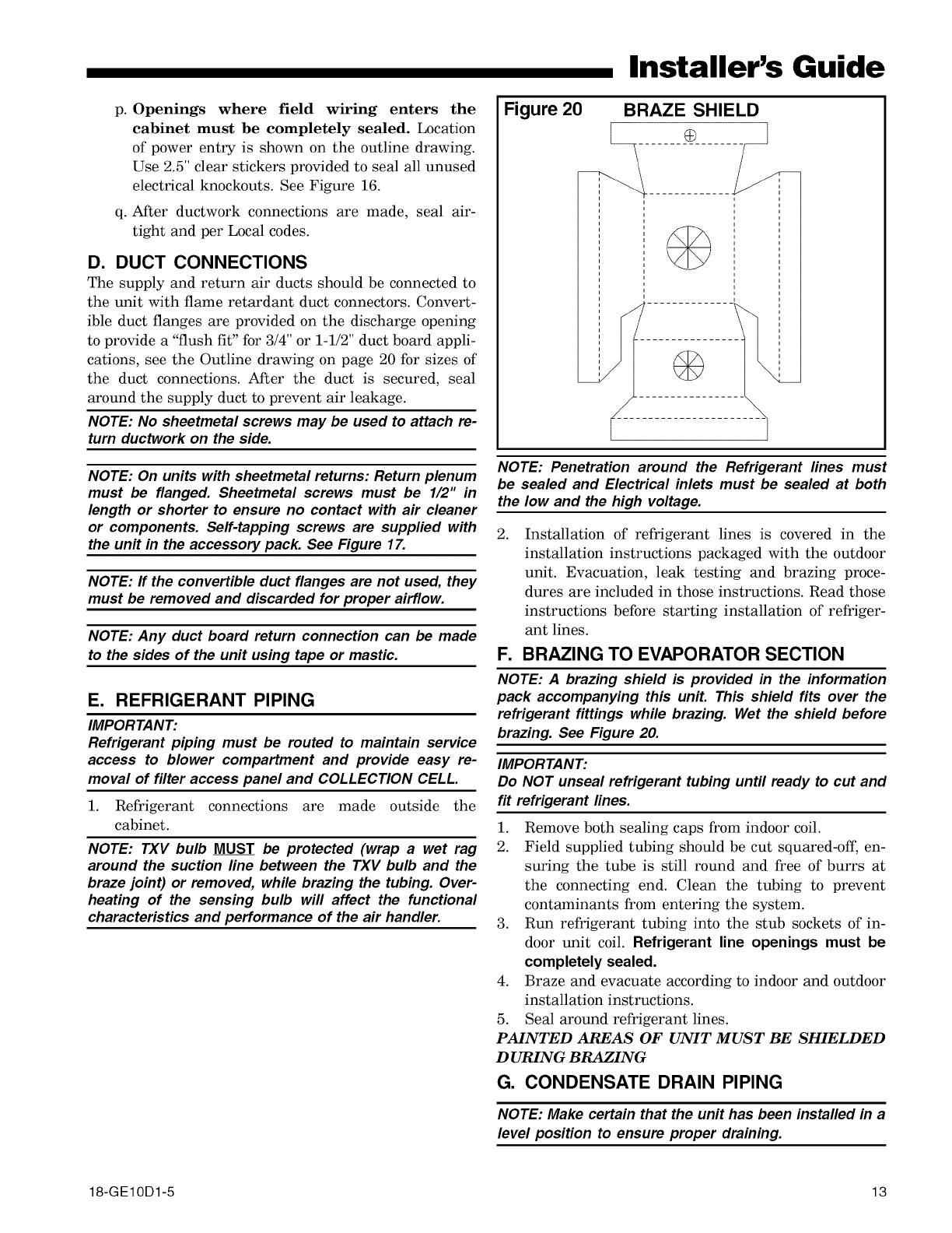
Figure 20 BRAZE SHIELD
........O.....
NOTE: Penetration around the Refrigerant lines must
be sealed and Electrical inlets must be sealed at both
the low and the high voltage.
.Installation of refrigerant lines is covered in the
installation instructions packaged with the outdoor
unit. Evacuation, leak testing and brazing proce-
dures are included in those instructions. Read those
instructions before starting installation of refriger-
ant lines.
F. BRAZING TO EVAPORATOR SECTION
NOTE: A brazing shield is provided in the information
pack accompanying this unit. This shield fits over the
refrigerant fittings while brazing. Wet the shield before
brazing. See Figure 20.
IMPORTANT:
Do NOT unseal refrigerant tubing until ready to cut and
fit refrigerant lines.
1. Remove both sealing caps from indoor coil.
2. Field supplied tubing should be cut squared-off, en-
suring the tube is still round and free of burrs at
the connecting end. Clean the tubing to prevent
contaminants from entering the system.
3. Run refrigerant tubing into the stub sockets of in-
door unit coil. Refrigerant line openings must be
completely sealed.
4. Braze and evacuate according to indoor and outdoor
installation instructions.
5. Seal around refrigerant lines.
PAINTED AREAS OF UNIT MUST BE SHIELDED
D URING BRAZING
G. CONDENSATE DRAIN PIPING
NOTE: Make certain that the unit has been installed in a
level position to ensure proper draining.
18-GE10D1-5 13

Installer's Guide
()
3/4" NPT
Secondary
drain
connection
Seal weep 1
hole except
for Downflow
configuration --
3/4" NPT
Primary drain
/connection
Figure 21
The indoor blower is downstream of the evaporator coil
which creates a negative pressure at the condensate
drain connections during operation. The condensate
drain connections in front of the indoor coil are 3/4"
NPT. The lower connection is the primary drain. See
Figure 21.
Two secondary drain connections are provided for the
different orientations (See Figure 21). The lower of the
two should be connected as a backup to prevent conden-
sate overflow by a blocked primary drain. The weep
hole in center of drain coupling area should be sealed
Manufactured traps
2" MINIMUM
2" MINIMUM
EZT-105 Figure 22
Field fabricated trap
CAP OR
2" MIN.
2" MIN.
I
i
I
Close as possible I
Trap must be within 4
of air handier condensate
drain connection, Figure 23
with caulk or RTV except in downflow unless secondary
drain is connected.
For proper drainage of condensate, the following steps
must be followed:
1. The primary drain line must be trapped with a
minimum of 2" water seal as shown in Figures 22 &
23. Do NOT use preformed 3/4" PVC running
traps.
The use of Field fabricated or manufactured traps
as shown in Figures 22 & 23 is acceptable. The
manufactured trap shown in Figure 22 allows for a
float switch option to be added.
Refer to the float switch manufacturers data and in-
structions for details.
2. The trap must be located within 4 feet of the air
handler drain outlet connection.
3. It is recommended that a clean-out tee or cross be
installed in the primary drain line for future main-
tenance (See Figures 22 & 23).
4. Do not use reducing fittings in the condensate drain
lines.
5. Slope the drain lines downward a minimum of 1/4"
per foot.
6. Insulate the primary drain to prevent sweating
where pipe temperature could meet or fall below
dewpoint temperatures.
7. Provide means for drainage to prevent winter
freeze-up of condensate line.
8. Do not connect the drain line to a closed drain sys-
tem.
9. Use Teflon _'_tape on the air handler drain line con-
nections! Do Not Use pipe joint compound or PVC/
CPVC cement!
It is always recommended that an auxiliary drain pan
be installed under a horizontally installed air handler.
Connect the auxiliary drain line to a separate drain line
(no trap is needed in this line) and terminate according
to National and Local codes.
NOTE: DO NOT use a torch or flame near the plastic
drain pan coupling.
NOTE: DO NOT tighten the drain pipe excessively. Sup-
port the condensate piping and traps outside the unit
to prevent strain on the drain coupling.
H. ELECTRICAL iPOWER WIRING
1. These Air Handlers are shipped from the factory
wired for 230 volts. The units may be wired for 208
volts. Follow instructions on unit wiring diagram lo-
cated on blower housing and in the Service Facts
document included with the unit.
2. The selection of wire and fuse sizes should be made
according to the Minimum Branch Circuit Ampacity
and the Maximum Overcurrent Device listed on the
unit nameplate.
14 18-GE10D1-5

Installer's Guide
TO PREVENT INJURY OR DEATH DUE TO ELECTRICAL
SHOCK OR CONTACT WITH MOVING PARTS, LOCK
UNIT DISCONNECT SWITCH IN OPEN POSITION BE-
FORE SERVICING UNIT.
.
4.
Field wiring diagrams for electric heaters and unit
accessories are shipped with the accessory.
Wiring must conform to National and Local codes.
If an electric heater is not installed, the Knockout
Plate provided in the Accessory Kit MUST be in-
stalled on the air handler and the conduit termi-
nated to it. The electrical connections are made us-
ing the two power leads and ground wire connec-
tions which are located near the discharge of the
blower.
NOTE: If air handler is used with or without a heater,
the electrical entry hole as well as any other cabinet
penetrations must be sealed air-tight.
I. CONTROL WIRING
1. Connect wiring between indoor unit, outdoor unit
and Comfort Control. The use of color-coded low-
voltage wires is recommended.
2. A low voltage terminal board is provided for control
wiring, and is located on the left side of the cross
brace in the center of the unit.
3. Field wiring diagrams are provided on page 18 and
19 which show the low voltage wiring hookup for a
single speed cooling only system (with supplemen-
tary heaters) and a heat pump system (with supple-
mentary heaters). Plug in type electrical connectors
are provided for use with supplementary heaters.
IMPORTANT:
When supplementary heaters are installed, inspect to
ECM FAN CONTROL
GFM
SELECTION DIP
.SWITCHES
/2'c8°°79°P°9
CNT03600
• F0123a56781
£ CFMFAN Y Y LO H
@H
z
W5W2Wl
Figure 24 From Dwg. 800796a
Figure 25
ooo...G.EAT..GFA.OFFAOX.' R
1"2-RFL_) 4 i Ai EiS iS
;°;1I;1I;I;
DIP SWITCHES (AS SHIPPED)
insure that all packaging material has been removed.
J. AIRFLOW ADJUSTMENT
Disconnect power to the air handler before changing
dip switch positions.
Failure to follow this procedure may result in equip-
ment damage.
Blower speed changes are made on the ECM Fan Con-
trol mounted inside the control box. The ECM Fan Con-
trol controls the variable speed motor.
There is a bank of 8 dip switches (See Figure 24). The
dip switches work in pairs to match the airflow for the
outdoor unit size (tons), cooling airflow adjustment, Fan
off-delay options, and heating airflow adjustment. The
switches appear as shown in Figure 25.
If the airflow needs to be increased or decreased, see
the Airflow Label on the air handler or the Blower Per-
formance Table in the Service Facts. Information on
changing the speed of the blower motor for your specific
outdoor model size is in the Blower Performance Table.
Be sure to set the airflow for the correct tonnage.
Refer to blower housing for correct setting.
Switches 1 - 4 Cooling Airflow
Switches 5 - 6 Fan Off Delay Options
Switches 7 - 8 Auxiliary Heat
If the optional humidistat is used, remove R-BK jumper
from the low voltage terminal board (not shown) and in-
stall the humidistat between R and BK. (Jumper R to O
for cooling-only/non-heat pump systems with a humidis-
tat.)
INDOOR BLOWER TIMING
The FAN-OFF period is set on the ECM Fan Control
board by dip switches #5 and #6. The blower off-delay
settings are as follows:
IMPORTANT:
Leave dip switch 5& 6 in the "as-shipped" position
during system start-up and check out. Afterwards,
adjust as desired.
18-GE10D1-5 15

Installer's Guide
FAN OFF - DELAY OPTIONS
NOMINAL
SELECTION AIRFLOW
SAME
100% *
50%
50 - 100%
NONE
1.5 MINUTES
3 MINUTES
I'4 ENHANC ED**
* - This setting is equivalent to the BAY24X045 relay benefit.
** - This ENHANCED MODE selection provides a ramping up
and ramping down of the blower speed to provide improved
comfort, quietness, and potential energy savings. The graph
shows the ramping process.
2. The FIELD CHARGER must be removed and
cleaned only by a qualified service professional.
3. The FIELD CHARGER must be cleaned at least once
a year.
4. The FIELD CHARGER may require more frequent
cleaning in homes with high indoor relative humid-
ity (greater than 65% RH).
5. Consult your service professional about cleaning
intervals.
High Voltage is present within the air cleaner for opera-
tion, Before removing the Filter Door or Panel, turn the
Comfort Control to the OFF position and disconnect all
sources of power to the unit and wait at least 15 seconds
to allow voltage to discharge.
Dehumidify
Fast Coil Cooling
and Heating
_' 7.5
minute minutes
100% if necessary
/
Efficiency
_.y.FF
,as required
o
minutes
I OFF
NOTE: Direct drive motors have bearings which are
permanently lubricated and under normal use lubrica-
tion is not recommended.
K. CHECKOUT PROCEDURE
NOTE: In normal operation, the air cleaner makes a
slight sound as the air passes through and is cleaned.
In some applications, you may notice this sound com-
ing from the return air vent(s). If desired, this sound
level can be reduced with minimal impact on air clean-
ing efficiency by reducing the power setting of the
FIELD CHARGER. The unit is shipped with the power
set at 9.6KV (high). If sound is heard, reduce power
level to 8.0KV (low) at the switch on the power supply.
See Figure 27.
1. Check the air handler installation in accordance
with the instructions on page 23.
L. INTEGRATED WHOLE HOUSE AIR
CLEANER MAINTENANCE
1. For maximum efficiency the COLLECTION CELL
should be inspected and cleaned on a regular basis.
NOTE: A 30 to 90 day cleaning interval is normal for the
COLLECTION CELL and should be adjusted based upon
unit run time and the home environment.
RISK OF ELECTRIC SHOCK:
These servicing instructions are for use by qualified
service technician. To reduce the risk of electric
shock, do not perform any servicing other than that
contained in these operating instructions unless you
are qualified to do so.
NOTE: System Information
Before cleaning the coil or ducts in the air handler,
remove the COLLECTION CELL and FIELD CHARGER
from the air cleaner. Chemicals used during the
cleaning of the air handler or ductwork can damage the
air cleaner components and degrade the performance
of the air cleaner.
M. CLEANING THE COLLECTION CELL
1. Turn the air conditioning system off at the Comfort
Control.
2. Loosen thumbscrews to remove the filter panel.
Remove the COLLECTION CELL by pulling for-
ward. See Figure 6.
CLEANING
The COLLECTION CELL may be cleaned either by
vacuuming (recommended method) or by washing
with water only.
VACUUM CLEANING
Remove COLLECTION CELL from conditioned
space. Vacuum both sides of the COLLECTION CELL
to clean.
WASHING
Use low-pressure water spray, such as a sink sprayer
or garden hose to clean the COLLECTION CELL.
Some residue may require warm water to be
removed.
•Do NOT use soap or detergent in cleaning the COL-
LECTION CELL.
•Do NOT immerse the COLLECTION CELL completely
16 18-GE10D1-5

Installer's Guide
in water.
• Do NOT place the COLLECTION CELL into a dish-
washer to clean.
•ALLOW THE COLLECTION CELL TO DRY THOR-
OUGHLY BEFORE REINSTALLING.
Slightly tap the COLLECTION CELL to remove
water retained. Allow the COLLECTION CELL to
completely dry before reinstalling.
N. CLEANING THE FIELD CHARGER
1. Turn the air conditioning system to the off position
at the Comfort Control. Loosen thumbscrews to re-
move the filter panel. Remove the COLLECTION
CELL by pulling forward. See Figure 6.
2. Use a 5/16" nutdriver to remove the screws holding
the FIELD CHARGER retainer bracket. See Fig-
ures 7 and 8.
3. Remove the FIELD CHARGER from the unit. Lay
the FIELD CHARGER on a secured flat surface.
FIELD CHARGER PINS ARE SHARP. DO NOT BEND
24 VAC Hot
24 VAC Common ii// Red
Return from air cleaner
Green
iJ LED
/
/
High voltage power lead
Pink High Voltage switch
9.6 to 8.0 KVDC
9.6 KVDC is right side down
8.0 KVDC is left side down
Figure 27
FIELD CHARGER PINS. WEAR APPROPRIATE
GLOVES WHEN HANDLING THE FIELD CHARGER.
4. Wipe down the face plate of the FIELD CHARGER
with a dry shop towel or use a vacuum cleaner.
NOTE: Do NOT disassemble the FIELD CHARGER.
5 Push a block of foam down over the FIELD
CHARGER Pin as in Figure 28.
6. Rotate the foam block on the FIELD CHARGER
Pin. See Figure 29.
7. Use the foam block to clean the faceplate opening
edges.
8. Repeat steps 5,6 and 7 for each FIELD CHARGER
Pin.
9. Put FIELD CHARGER back into the air handler
and secure the FIELD CHARGER in place with the
retainer bracket. See Figure 7.
10. Reinstall COLLECTION CELL.
11. Put filter panel back in place.
Figure 28
'2
Figure 29
18-GE10D1-5 17

Installer's Guide
2/4TEE3D31,37, 40, 49 & 65A AIR HANDLERS WITH SINGLE STAGE COOLING,
2 STAGE HEAT
COMFORT CONTROL
2 - STAGE HEAT/
I - STAGE COOL
_NOTE 5
NOTE 5
VARIABLE SPEED
AIR HANDLER
COOLING
O.D. SECTION
(SINGLE SPEED)
HUMIDI_TA_
NOTE 4/
_NOTE 4
NOTES:
I LOW VOLTAGE WIRING TO BE NO
IB AWG MINIMUM CONDUCTOR
WHEN HEATERS ARE USED, DISCARD
POWER LEADS WITH POLARIZED PLUG
PM A AND CONNECT I PF TO MATING
PLUG IN THE HEATER CONTROL BOX
AS SHOWN
TERMINAL WR WILL HAVE INTERNAL
CONNECTIONS ONLY IF 2ND
CONTACTOR IS USED BY THE HEATER
FOR CONTROLLING POWER TO
ELECTRIC HEATING ELEMENTS IF
2ND (BH) CONTACTOR IS NOT USED,
THEN FIELD CONNECTIONS TO W2 CAN
BE OMITTED AS APP#OPRIATE
4 CONNECTIONS TO "R","BK",
"0" AND "Y" MUST BE MADE AS
SHOWN FOR PROPER OPERATION
OF BLOWER WITH HUMIDISTAT IN
COOLING
5 SEE HEATER WIRING DIAGRAM FOR
HEATING ANTICIPATOR SETTING
INTER COMPONENT WIRING
24 v FIEL@
_LI_E V)WIRIN6
From Dwg. No. B801074
2/4TEE3D31, 37, 40, 49 & 65A AIR HANDLERS WITH TWO STAGE COOLING, 2 STAGE HEAT
COM FORT CONTROL
VARIABLE SPEED 2 STAGE
AIR HANDLER AIR CONDITIONER
ZrL R
NOTES
I. BE SURE POWERSUPPLY AGREES
WITH EQUIPMENT NAMEPLATE.
2. POWERWIRING AND GROUNDINGOF
EQUIPMENT MUST COMPLYWITH
LOCAL CODES.
3. LOW VOLTAGE WIRING TO BE NO. 18
AWGMINIMUM CONDUCTOR.
4. IF OUTDOORTHERMOSTAT(ODT)IS
NOT USED, CONNECT W2 TO WS.
24V INTER-COMPONENTWIRING
(FACTORY) (FIELD)
(WIRING) (WIRING)
PRINTED FROM BI52935P03
18 18-GE10D1-5

Installer's Guide
2/4TEE3D31, 37, 40, 49 & 65A AIR HANDLERS WITH SINGLE STAGE HEAT PUMP
COMFORT VARIABLE SPEED
CONTROL AIR HANDLER
.,,_--INU IL ©
%
%
NOTE 3 &4-_:
i
NOTE 7_ [_
%
SEE NOTE 2
I-PF'_pM- A
SUPPL. NTR.
CONTROL BOX EO.
FOR
f3 PH
TO POWER SUPPLY
PER LOCAL CODES &
AS DEFINED IN
FIELD WIRING TABLE
o.,,_._o__
HUMIDISTAT
NOTE 5
i
BR/X2oRBK
NOTE 6
TO POWERSUPPLY
PER LOCAL CODES
HEAT PUMP
O.D. SECTION
(SINGLE SPEED)
_--T
_'---F
III "-
NOTES
I. LOW VOLTAGE WIRING TO BE NO,
18 AIW.G. MINIMUM CONDUCTOR.
2. WHEN HEATERS ARE USED, DISCARD
POWERLEADS WITH POLARIZED PLUG
PM-A AND CONNECT I-PF TO MATING
PLUG IN THE HEATER CONTROL BOX
AS SHOWN.
3. TERMINAL W2 WILL HAVE INTERNAL
CONNECTIONS ONLY IF 2ND
CONTACTOR IS USED BY THE HEATER
FOR CONTROLLING POWERTO
ELECTRIC HEATING ELEMENTS. IF
2ND (BH) CONTACTOR IS NOT USED,
THEN FIELD CONNECTIONS TO W2
CAN BE OMITTED AS APPROPRIATE.
4. IF ODT IS NOT USED, THEN
CONNECT APPROPRIATE JUMPER
FROM Wl TO W2 TO W3 ON LVTB.
5. IF HUMIDISTAT IS NOT USED,
CONNECT JUMPER FROM IIRll TO
IIBKII FOR FULL TONNAGE AIRFLOW
IN COOLING.
6. CONNECT IN THIS MANNER IF
O,D. UNIT HAS IIFll CONNECTION.
7. CONNECT W3 TO W2 ONLY IF USING
HEATER WITH 3 HEATER STAGES,
8, SEE HEATER WIRING DIAGRAM FOR
HEATING ANTICIPATOR SETTING.
INTER-COMPONENTWIRING
...... 24 V. 1FACTORY
=LINE v.jWlRING
24 V, )FIELD
LINE V, WIRING
From Dwg. No. B801077
18-GE10D1-5 19

Installer's Guide
OUTLINE DRAWING FOR 2/4TEE3D31,37, 40, 49 & 65A1000A
1
B
-._1 oo_.- 1 DISCHARGE
S OPENING
(SEE FIG I
6 FIG 2:,
HEATER K 0
TOP VIEW
HE_TER
/
/
._88 :_
SIDE VIEW
'-°!l
(OPEriNO
BOTTOM VIEW
IDo _
G_S LINE
SEE T_SLE_\
\
AIRFLOW
it
CIR( IT
5REAKER
___LTE :_t "_
ACCES
VERTICAL UPFLOW
FIG, IFIG. 2
J K J K
19 518 5
2TEESi)31 2TEESF39 4TEESI)3I' 4TEESF39
2TEESC3 , 2TEESF,8, 4TEE CB% 4TEESF48 120 21 5 II 0 2O 5
2TEESFO8 TEESF64
2TEESD40, 4TEES840, 2TEESC40 4TEESC40
2TEEBD 9, 4TEESO49, 2TEEBC49, 4TEE C89 2 0 23 0
;'TEES}O5 4TEES)65 2TEESC65 4TEE3065
FIG. I
KDISCHARGE
OPENING
I 64 _
©@
FIG, 2
_HNINUM UNIT ,;LE_R_r4CE TABLE
T:
o SER/ICE
COMBUSTIBLE
M&TERIAL CLE#RANCE
IIREOUII_ED) I:IRECOMMENDE_)
SIi}E6 0 II _11
FRONT 0" I"
I_aLET DUCT 0"
OUTLET DUCT I"_
I" FOR THE FIRST 3 FT OF OdTLET DUCT
'_HEN ELE{TRIC HE;TERS _RE INST;LLED
MODELN_
2TEEB_31, 4TEESDSI
2TEEBCSI 4TEESCBI
2TEE39}7, 2TEE}C37
2TEE5940, _TEEBC40
2TEES_49, 2TEEBC49
2TEES_b, 2TEESC65
4TEESD37 4TEESCS7
4TEESD40 4TEESC40
4TEESD49 4TEEBC49
4TEE_D65 4TEE}CO5
_TEEBF39
4TEE?FB9
2TEE_F48 2TEESF64
4TEESF48, 4TEESF64
FLOW GASLINE go. UNE
A B C D E F G CONTROL BR_ BR_
43 21 'C 1950 15 3' _'16
362 I89
23 53 21 50 I' 5' _/A '8
51 7 18 B
9u 2_ 24 321 I 48
27 12 11,8
62 75 36 00
45 23 50 2150 1757 S62 I 89
51 _5 18 33 /A TX,/NB 3/4 5,%
[ 90 26 24 27 18 S 21 I 48
62 75 B6 00 7'8
9O Ii' 00 Sl 15
235,3 2150 862 I 89
57 9D 2677 51 IS 7,'6
From Dwg. D802101 Rev. 5
20 18-GE10D1-5

Installer's Guide
2/4TEE3D31, 37, 40, 49 & 65A AIR HANDLER DIMENSIONAL DATA
Model No. H W
2/4TE E3D31A 43.00 21.50
2/4TEE3D37A 45.00 23.50
2/4TEE3D40A 51.75 26.00
2/4TEE3D49A 57.90 26.00
2/4TEE3D65A 62.75 26.00
H
18-GE10D1-5 21

Installer's Guide
EXPLODED VIEW
r
0
_J
_J
From Dwg. D802038g05 Rev. 11
22 18-GE10D1-5

Installer's Guide
CHECKOUT PROCEDURES
After installation has been completed, it is recommended that the Air Handler be checked against the following
checklist.
1. Make sure power is "OFF" at power disconnect
switch .................................................................... [ ]
2. Check all field wiring for tight connections. See that
grounding of unit is in accord with code .............. [ ]
3. Make sure unit suspension (if used) is secure and
that there are no tools or loose debris in, around or
on top of the unit .................................................. [ ]
4. Check all duct outlets; they must be open and
unrestricted .......................................................... [ ]
5. Check drain lines and be sure all joints are tight [ ]
6. Make sure secondary drain pan is installed ........ [ ]
7. Cheek power supply for correct requirements per
unit nameplate ..................................................... [ ]
8. Inform owner of proper procedure for cleaning
COLLECTION CELL ........................................... [ ]
9. Energize the system and carefully observe its opera-
tion; make any necessary adjustment ................. [ ]
10. Instruct owner on proper operating procedure and
leave Use and Care Manual with owner ............. [ ]
11. Check the integrated whole electronic air cleaner
power output by the Green LED illumination. If the
LED is on, this indicates High Voltage output to the
air cleaner ............................................................. [ ]
12. Cheek to make sure the electronic air cleaner is
working ................................................................. [ ]
a) Turn off Comfort Control.
b) Remove air handler top panel.
e) Disconnect the 5-pin High Voltage connector to
the variable speed motor.
RISK OF ELECTRICAL SHOCK:
ELECTRICAL POWER IS PRESENT FOR THE NEXT 5
STEPS. THESE STEPS SHOULD BE PERFORMED
ONLY BY QUALIFIED SERVICE TECHNICIAN.
FAILURE TO FOLLOW THIS WARNING COULD RE-
SULT IN PERSONAL INJURY, ELECTRICAL SHOCK,
OR DEATH.
d) Turn the system power On.
e) Turn the Comfort Control to the Fan only posi-
tion.
fl Check for LED illumination on the power sup-
ply to the air cleaner. LED illumination indi-
cates High Voltage power is present to the air
cleaner.
g) Turn the Comfort Control to the Off position.
h) Turn the system power Off.
i) Reconnect the 5-pin High Voltage connector to
the variable speed motor.
Replace the air handler top panel.j)
k) Turn the Comfort Control back on.
SUPPLEMENTARY HEATERS CHECKOUT PROCEDURES,
IF a heater is USED, see "limitations and recommendations"
to determine if the heater requires a SPECIAL CIRCUIT.
1. Be sure the disconnect switch is "OFF", and safety label (if any) is attached ............................... [
2. Check on field wiring for tight connections and grounding according to codes ............................ [
3. Check circuit protection for proper size per nameplate specifications .......................................... [
]
]
]
4. Check control box panel -- in place and secured ........................................................................... [ ]
NOTE: OPERATION OF HEATERS MUST BE CHECKED DURING THE OPERATION CHECK OF THE
TOTAL SYSTEM.
18-GE10D1-5 23

Trane
6200 Troup Highway
Tyler, TX 75707
For more information contact
your local dealer (distributor)
02/08
The manufacturer has a policy of continuous product and product data improvement, and it reserves the
right to change design and specifications without notice.
