TRENDNET TEW432BRP 802.11g Wireless Broadband Router User Manual
TRENDNET, INC. 802.11g Wireless Broadband Router
UserManual.wiki
>
TRENDNET
>
TEW432BRP User Manual
>
Users Manual 1
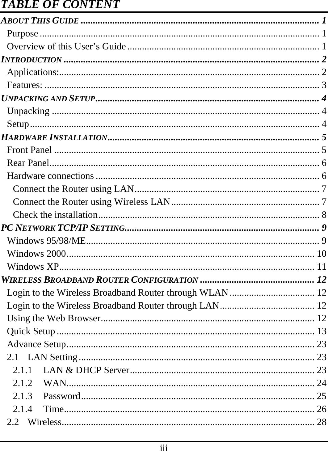
Contents
1.
Users Manual 1
2.
Users Manual 2
Users Manual 1
Navigation menu
Upload a User Manual
Namespaces
Wiki Guide
HTML
PDF
Info
Views
User Manual
Discussion / Help
Navigation