TRENDNET TEW432BRP 802.11g Wireless Broadband Router User Manual
TRENDNET, INC. 802.11g Wireless Broadband Router
TRENDNET >
Contents
- 1. Users Manual 1
- 2. Users Manual 2
Users Manual 1

i
Regulatory notes and statements
Wireless LAN, Health and Authorization for use
Radio frequency electromagnetic energy is emitted from Wireless LAN devices.
The energy levels of these emissions however are far much less than the
electromagnetic energy emissions from wireless devices like for example mobile
phones. Wireless LAN devices are safe for use frequency safety standards and
recommendations. The use of Wireless LAN devices may be restricted in some
situations or environments for example:
·On board of airplanes, or
·In an explosive environment, or
·In case the interference risk to other devices or services is perceived or identified
as harmful
In case the policy regarding the use of Wireless LAN devices in specific
organizations or environments (e.g. airports, hospitals, chemical/oil/gas industrial
plants, private buildings etc.) is not clear, please ask for authorization to use these
devices prior to operating the equipment.
Regulatory Information/disclaimers
Installation and use of this Wireless LAN device must be in strict accordance with
the instructions included in the user documentation provided with the product. Any
changes or modifications made to this device that are not expressly approved by the
manufacturer may void the user’s authority to operate the equipment. The
Manufacturer is not responsible for any radio or television interference caused by
unauthorized modification of this device, of the substitution or attachment.
Manufacturer and its authorized resellers or distributors will assume no liability for
any damage or violation of government regulations arising from failing to comply
with these guidelines.
Federal Communication Commission Interference Statement
This equipment has been tested and found to comply with the limits for a
Class B digital device, pursuant to Part 15 of the FCC Rules. These limits
are designed to provide reasonable protection against harmful interference
in a residential installation. This equipment generates, uses and can radiate
radio frequency energy and, if not installed and used in accordance with the
instructions, may cause harmful interference to radio communications.
However, there is no guarantee that interference will not occur in a
particular installation. If this equipment does cause harmful interference to
radio or television reception, which can be determined by turning the

ii
equipment off and on, the user is encouraged to try to correct the
interference by one of the following measures:
- Reorient or relocate the receiving antenna.
- Increase the separation between the equipment and receiver.
- Connect the equipment into an outlet on a circuit different from that
to which the receiver is connected.
- Consult the dealer or an experienced radio/TV technician for help.
FCC Caution: Any changes or modifications not expressly approved by the
party responsible for compliance could void the user's authority to operate
this equipment.
This device complies with Part 15 of the FCC Rules. Operation is subject to
the following two conditions: (1) This device may not cause harmful
interference, and (2) this device must accept any interference received,
including interference that may cause undesired operation.
IMPORTANT NOTE:
FCC Radiation Exposure Statement:
This equipment complies with FCC radiation exposure limits set forth for an
uncontrolled environment. This equipment should be installed and operated
with minimum distance 20cm between the radiator & your body.
We declare that the product is limited in CH1~CH11 by specified firmware
controlled in the USA.
This transmitter must not be co-located or operating in conjunction with any
other antenna or transmitter.

iii
TABLE OF CONTENT
ABOUT THIS GUIDE .................................................................................................. 1
Purpose................................................................................................................... 1
Overview of this User’s Guide............................................................................... 1
INTRODUCTION ......................................................................................................... 2
Applications:........................................................................................................... 2
Features: ................................................................................................................. 3
UNPACKING AND SETUP............................................................................................ 4
Unpacking .............................................................................................................. 4
Setup....................................................................................................................... 4
HARDWARE INSTALLATION....................................................................................... 5
Front Panel ............................................................................................................. 5
Rear Panel............................................................................................................... 6
Hardware connections ............................................................................................ 6
Connect the Router using LAN............................................................................ 7
Connect the Router using Wireless LAN............................................................. 7
Check the installation........................................................................................... 8
PC NETWORK TCP/IP SETTING................................................................................ 9
Windows 95/98/ME................................................................................................ 9
Windows 2000...................................................................................................... 10
Windows XP......................................................................................................... 11
WIRELESS BROADBAND ROUTER CONFIGURATION ............................................... 12
Login to the Wireless Broadband Router through WLAN................................... 12
Login to the Wireless Broadband Router through LAN....................................... 12
Using the Web Browser........................................................................................ 12
Quick Setup.......................................................................................................... 13
Advance Setup...................................................................................................... 23
2.1 LAN Setting................................................................................................. 23
2.1.1 LAN & DHCP Server............................................................................ 23
2.1.2 WAN...................................................................................................... 24
2.1.3 Password................................................................................................ 25
2.1.4 Time....................................................................................................... 26
2.2 Wireless........................................................................................................ 28

iv
2.2.1 Basic ...................................................................................................... 28
2.2.2 Authentication ....................................................................................... 29
2.2.3 Advanced............................................................................................... 32
2.3 Status............................................................................................................ 33
2.3.1 Device Information................................................................................ 33
2.3.2 Log......................................................................................................... 34
2.3.3 Log Setting ............................................................................................ 36
2.3.4 Statistic .................................................................................................. 37
2.3.5 Wireless................................................................................................. 38
2.4 Routing......................................................................................................... 39
2.4.1 Static...................................................................................................... 39
2.4.2 Dynamic ................................................................................................ 40
2.4.3 Routing Table........................................................................................ 41
2.5 Access .......................................................................................................... 42
2.5.1 MAC Filters........................................................................................... 42
2.5.2 Protocol Filter........................................................................................ 43
2.5.3 IP Filter.................................................................................................. 44
2.5.4 Virtual Server ........................................................................................ 45
2.5.5 Special AP ............................................................................................. 46
2.5.6 DMZ ...................................................................................................... 48
2.5.7 Firewall Rule ......................................................................................... 49
2.6 Management................................................................................................. 51
2.6.1 Remote Management............................................................................. 51
2.7 Tools ............................................................................................................ 52
2.7.1 Reset ...................................................................................................... 52
TECHNICAL SPECIFICATIONS ................................................................................. 56

1
ABOUT THIS GUIDE
Congratulations on your purchase of this IEEE 802.11g Wireless Broadband Router.
This integrated access device combines Internet gateway functions with wireless
LAN and Fast Ethernet switch. It provides a complete solution for Internet surfing
and office resources sharing, and it is easy to configure and operate for every users.
Purpose
This manual discusses how to install the IEEE 802.11g Wireless Broadband Router.
Overview of this User’s Guide
Introduction. Describes the Wireless Broadband Router and its features.
Unpacking and Setup. Helps you get started with the basic installation of the
Wireless Router.
Identifying External Components. Describes the front panel, rear panel and LED
indicators of the Wireless Router.
Connecting the Router. Tells how you can connect the Wireless Router to your
xDSL/Cable Modem.
Technical Specifications. Lists the technical (general, physical and environmental,
performance and Routers settings) specifications of the Wireless Broadband Router.
Note: Always run the CD and follow the steps in the Quick Installation Guide first
to setup your router. If you still have problems after doing so then proceed to the
following paragraphs to install the router with web-based configuration.

2
INTRODUCTION
With the explosive growth of the Internet, accessing information and services at
any time, day or night has become a standard requirement for most people. The era
of the standalone PC is waning. Networking technology is moving out of the
exclusive domain of corporations and into homes with at least two computers.
This integrated access device combines Internet gateway functions with wireless
LAN and Fast Ethernet switch. Designed for the business and home, it saves you
the cost of installing a separate modem and ISP line for each computer, while
providing ready connection for the users, with or without the network wires.
Broadband network access is also gaining ground. However, allowing more than
two computers to access the Internet at the same time means less affordable, higher
costs. Thus, there is a need to share one legal IP address over a single Internet
connection to link the home with the Internet.
The scarcity of IP addresses and using a shared Internet connection through an
Internet sharing device can solve high network access costs. All linked computers
can make full use of broadband capabilities over such a device.
This device not only comes equipped with a wide range of features, but also can be
installed and configured right out of the box. This device supports a simple local
area network and Internet access share, offering great cost savings.
The local area network connects up home computers while also allowing any of the
computers to access the Internet, share resources, or play online games—the basis
of the family computing lifestyle.
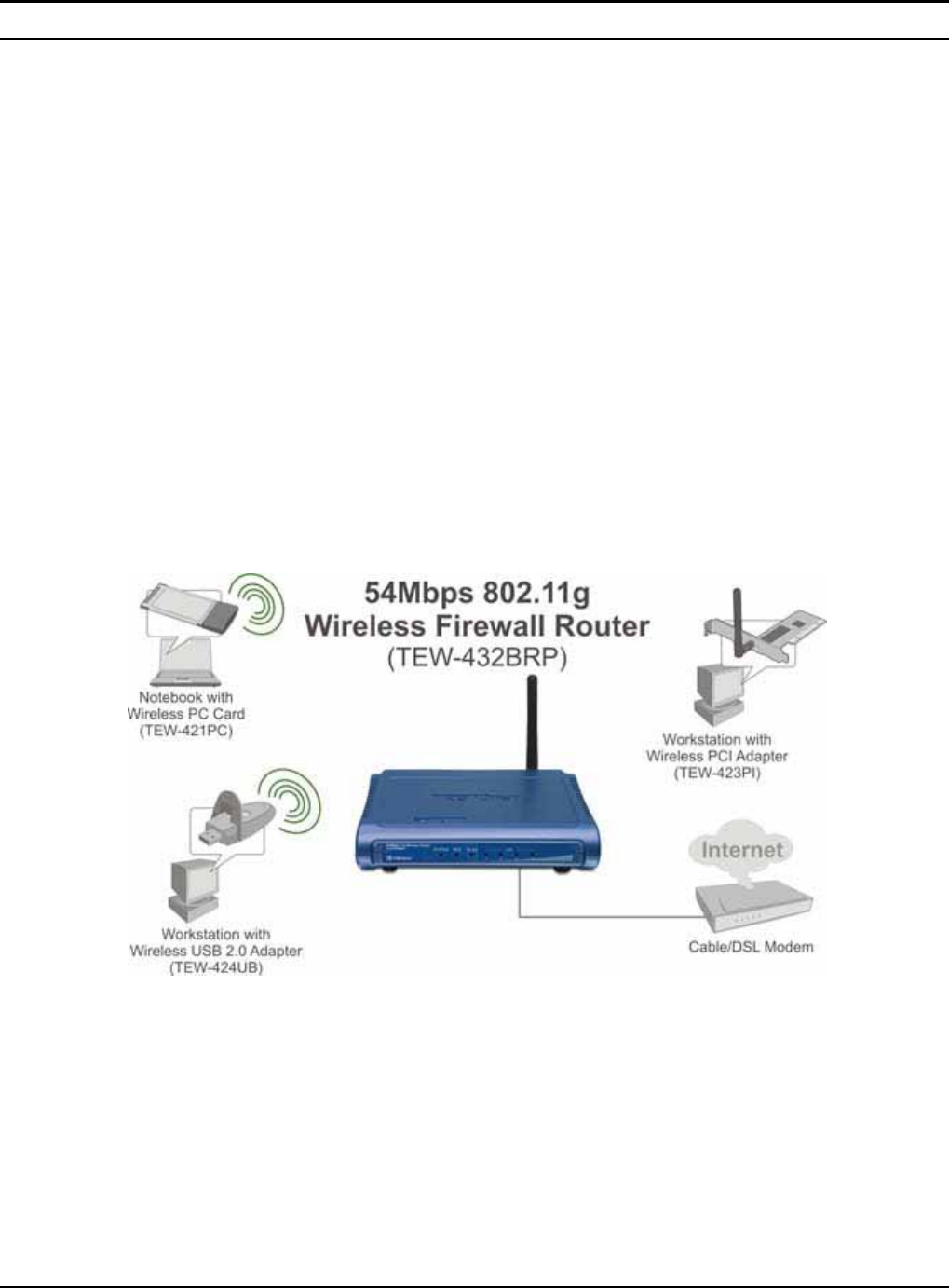
Applications:
Broadband Internet access:
Several computers can share one high-speed broadband connection through
wireless or wired (WLAN, LAN and WAN-Internet).
Resource sharing:
Share resources such as printers, scanners and other peripherals.
File sharing:
Exchange data, messages, and distribute files thus making good use of hard disk
space.
Online gaming:
Through the local area network, online gaming and e-commerce services can be
easily setup.
Firewall:
A built-in firewall function — for security and anti-hack system.

3
Features:
Wi-Fi Compliant with IEEE 802.11g and 802.11b Devices
Built-in 4 x 10/100Mbps Auto-MDIX LAN Ports
Built-in 1 x 10/100Mbps Auto-MDIX WAN Port (Internet)
Supports Cable/DSL Modems with Dynamic IP, Static IP, PPPoE, or PPTP
Connection Types
DHCP Server Feature Allocates up to 253 Client IP Addresses
Supports 64/128-bit Wired Equivalent Privacy (WEP)
Supports WPA, WPA-PSK, TKIP/AES and 802.1X for Advance Security
Supports MAC Address, Protocol Filters and UPnP (Universal Plug & Play)
Traffic Control with Virtual Server, Virtual PC mapping and DMZ
Provides Additional Security with SPI / NAT firewall and Attack Alert via
emails
Provides Additional Security of Enable/Disable SSID, Password Protection
Supports Static and Dynamic Routing
Flash Memory for Firmware Upgrade, Save/Restore Settings, and Traffic
Log
Compliant with Windows 95/98/NT/2000/XP, Linux and Mac OS
Easy Management via Web Browser (HTTP) and Remote Management
Range for Indoor of 30 ~ 50 meters (depends on the environment)
Range for Outdoor of 50 ~ 200 meters (depends on the environment)

4
UNPACKING AND SETUP
This chapter provides unpacking and setup information for the Wireless Broadband
Router.
Unpacking
Open the box of the Wireless Broadband Router and carefully unpack it. The box
should contain the following items:
TEW-432BRP Wireless Router
Multi-Language Quick Installation Guide
Easy-Go Installation CD
5V 2.5A External Power Adapter
RJ-45 Cable
If any item is found missing or damaged, please contact your local reseller for
replacement.
Setup
The setup of the Wireless Broadband Router can be performed properly using the
following methods:
The power outlet should be within 1.82 meters (6 feet) of the Broadband Router.
Visually inspect the DC power jack and make sure that it is fully secured to the
power adapter.
Make sure that there is proper heat dissipation from and adequate ventilation
around the Broadband Router. Do not place heavy objects on the Broadband
Router.
Fix the direction of the antennas. Try to place the Wireless Router in a position
that can best cover your wireless network. Normally, the higher you place the
antenna, the better the performance will be. The antenna’s position enhances the
receiving sensitivity.
5
HARDWARE INSTALLATION
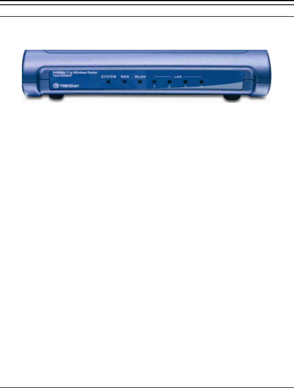
Front Panel
The figure below shows the front panel of the Wireless Broadband Router.
TEW-432BRP Front Panel
POWER
This indicator lights green when the hub is receives power, otherwise it is off.
SYSTEM
This indicator blinks green means the Internet Broadband Router is working
successful. Otherwise, this indicator always on or off means the function of the
Internet Broadband Router is fail.
WAN (Link/ACT)
The indicators light green when the WAN port was connected to an xDSL/Cable
modem successfully.
The indicators blink green while the WAN port was transmitting or receiving data
on the xDSL/Cable modem.
WLAN (ACT)
This indicator lights green when there are wireless devices connected and
transmitting data to the Wireless Router.
LAN (Link/ACT)
These indicators light green when the LAN ports were connected successfully.
These indicators blink green while the LAN ports were transmitting data.
6
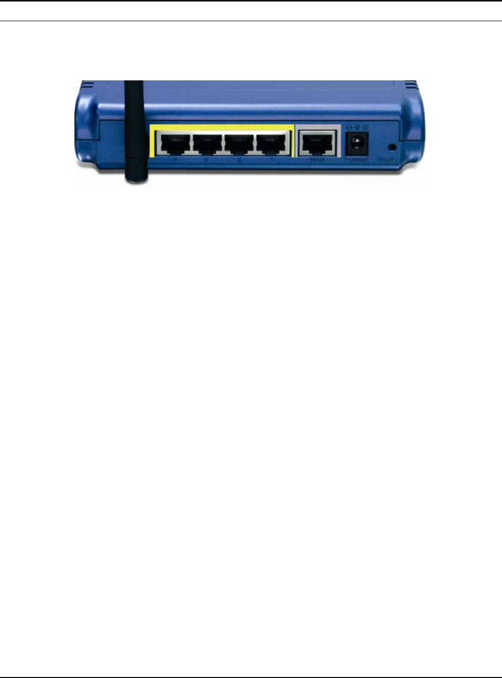
Rear Panel
The figure below shows the rear panel of the Wireless Broadband Router.
TEW-432BRP Rear Panel
Antenna
There are one 2 dBi Gain Antenna in the rear panel for wireless connection.
LAN (1-4)
Four RJ-45 10/100Mbps Auto-MDIX ports for connecting to either 10Mbps or
100Mbps Ethernet connections.
WAN
In the four port broadband router, there is an RJ-45 10/100Mbps Auto-MDIX port
for the WAN that will fit the xDSL/Cable modem’s specification need.
DC IN
Plug the power adapter to this power jack
RESET
Use a pin-shape item to push to reset this device to factory default settings. It will
be useful too when the manager forgot the password to login, but the setting will be
back to default setting.
7
Hardware connections
Connect the Router using LAN
1. Plug in one end of the network cable to the WAN port of the Wireless Internet
Broadband Router.
2. Plug in the other end of the network cable to the Ethernet port of the xDSL or
Cable modem.
3. Use another network cable to connect to the Ethernet card on the computer
system; the other end of the cable connects to the LAN port of the Internet
Broadband Router. Since the Wireless Broadband Router has four ports, you can
connect up to four computers directly to the unit. There you do not have to buy a
switch to connect these computers since one Internet Broadband Router
functions both as a connection-sharing unit and as a switch.
Connect the Router using Wireless LAN
1. Plug in one end of the RJ45 network cable to the xDSL/Cable Modem.
2. Plug in the other end of the RJ45 network cable to the Wireless Internet
Broadband Router WAN port.

8
Check the installation
The control LEDs of the Wireless Internet Broadband Router are clearly visible and
the status of the network link can be seen instantly:
1. With the power source on, once the device is connected to the broadband modem,
the Power, CPU, LAN, WLAN and WAN port link LEDs of the Internet
Broadband Router will light up indicating a normal status.
2. While the WAN is link up to the ADSL/Cable modem, the WAN port’s
Link/ACT LED will light up.
3. While the LAN is link up to the computer system, the LAN port’s Link/ACT
LED will light up.
9
PC NETWORK TCP/IP SETTING
The network TCP/IP settings differ based on the computer’s operating system
(Win95/98/ME/NT/2000/XP) and are as follows.
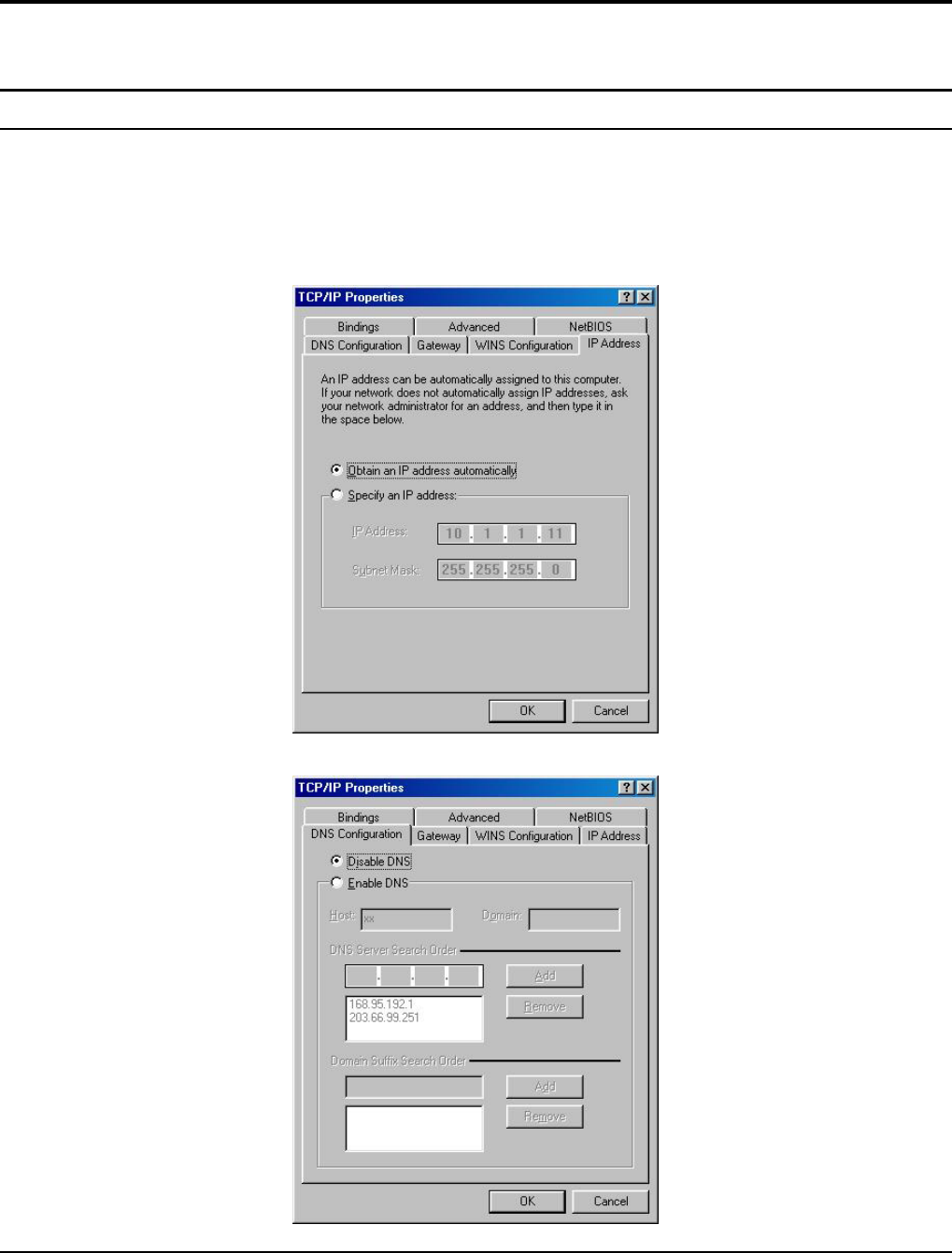
Windows 95/98/ME
1. Click on the “Network neighborhood” icon found on the desktop.
2. Click the right mouse button and a context menu will be show.
3. Select “Properties” to enter the TCP/IP setting screen.
4. Select “Obtain an IP address automatically” on the “IP address” field.
5. Select “Disable DNS” in the “DNS” field.
10
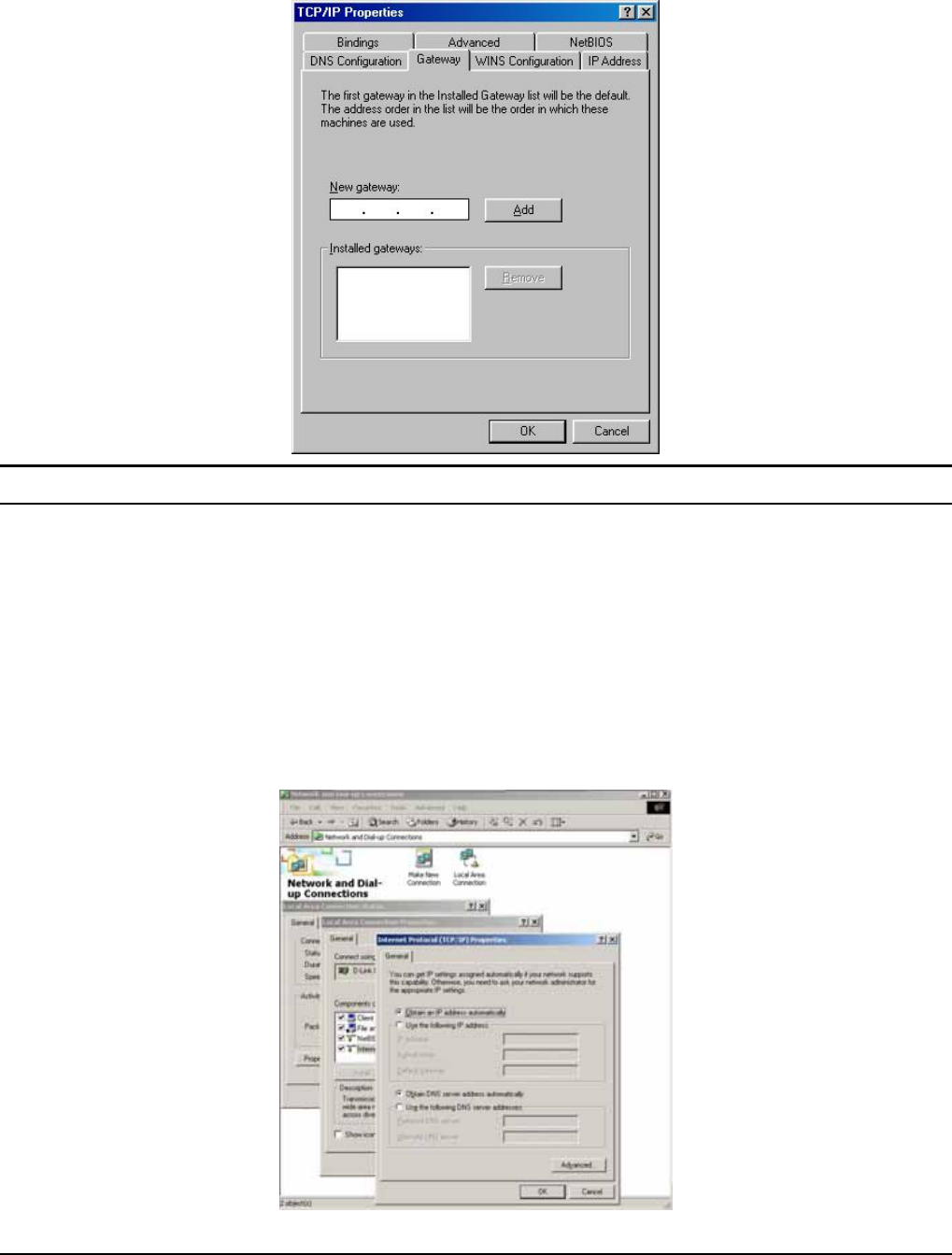
6. Select “None” for the “Gateway address” field.
Windows 2000
Double click on the “My computer” icon on the desktop. When “My computer”
window opens, open the “Control panel” and then open the “Network dialup
connection” applet. Double click on the “Local area network connection” icon.
Select “Properties” to enter the TCP/IP setting window.
1. In the “Local area network status” window, click on “Properties.”
2. In the “Local area network connection” window, first select TCP/IP setting
and then select “Properties.”
3. Set both “IP address” and “DNS” to Automatic configuration.
11
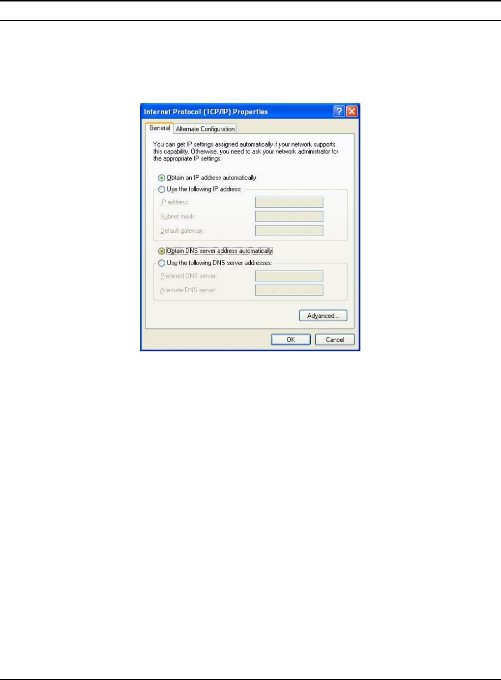
Windows XP
Point the cursor and click the right button on the “My Network Place” icon.
Select “properties” to enter the TCP/IP setting window.
1. Set “IP address” to “Obtain an IP address automatically.”
2. Set “DNS” to “Obtain DNS server address automatically.”
12
WIRELESS BROADBAND ROUTER CONFIGURATION
First make sure that the network connections are functioning normally.
This Wireless Broadband Router can be configured using Internet Explorer 4.0 or
newer web browser versions.
Login to the Wireless Broadband Router through WLAN
Before configuring the Wireless Broadband Router through WLAN, make sure that
the SSID, Channel and the WEP is set properly.
The default setting of the Wireless Broadband Router that you will use:
SSID: default
Channel: 6
Security: disable
Login to the Wireless Broadband Router through LAN
Before you configure this device, note that when the Wireless Broadband Router is
configured through an Ethernet connection, make sure the host PC must be set on
the IP sub-network that can be accessed by the xDSL/Cable modem. For example,
when the default network address of the xDSL/Cable modem Ethernet interface is
192.168.1.x, then the host PC should be set at 192.168.1.xxx (where xxx is a
number between 2 and 254), and the default subnet mask is 255.255.255.0.
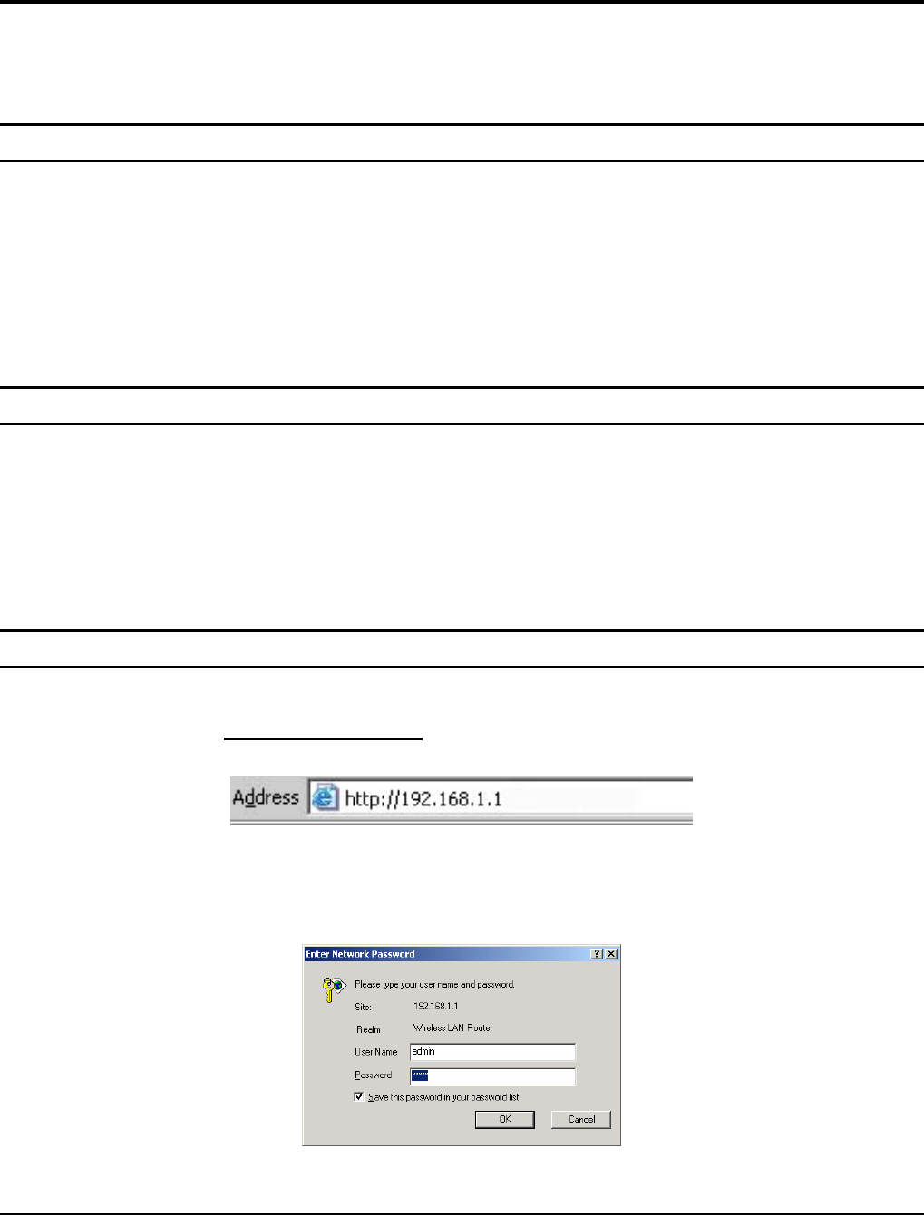
Using the Web Browser
1. Open Internet Explorer 4.0 or above Internet browser.
2. Enter IP address http://192.168.1.1 (the factory-default IP address setting) to the
URL web address location.
3. When the following dialog box appears, enter the user name and password to
login to the main configuration window, the default username and password is
“admin”.
Note: If needed to set a password, then refer to the Main Page Password Setting.
13
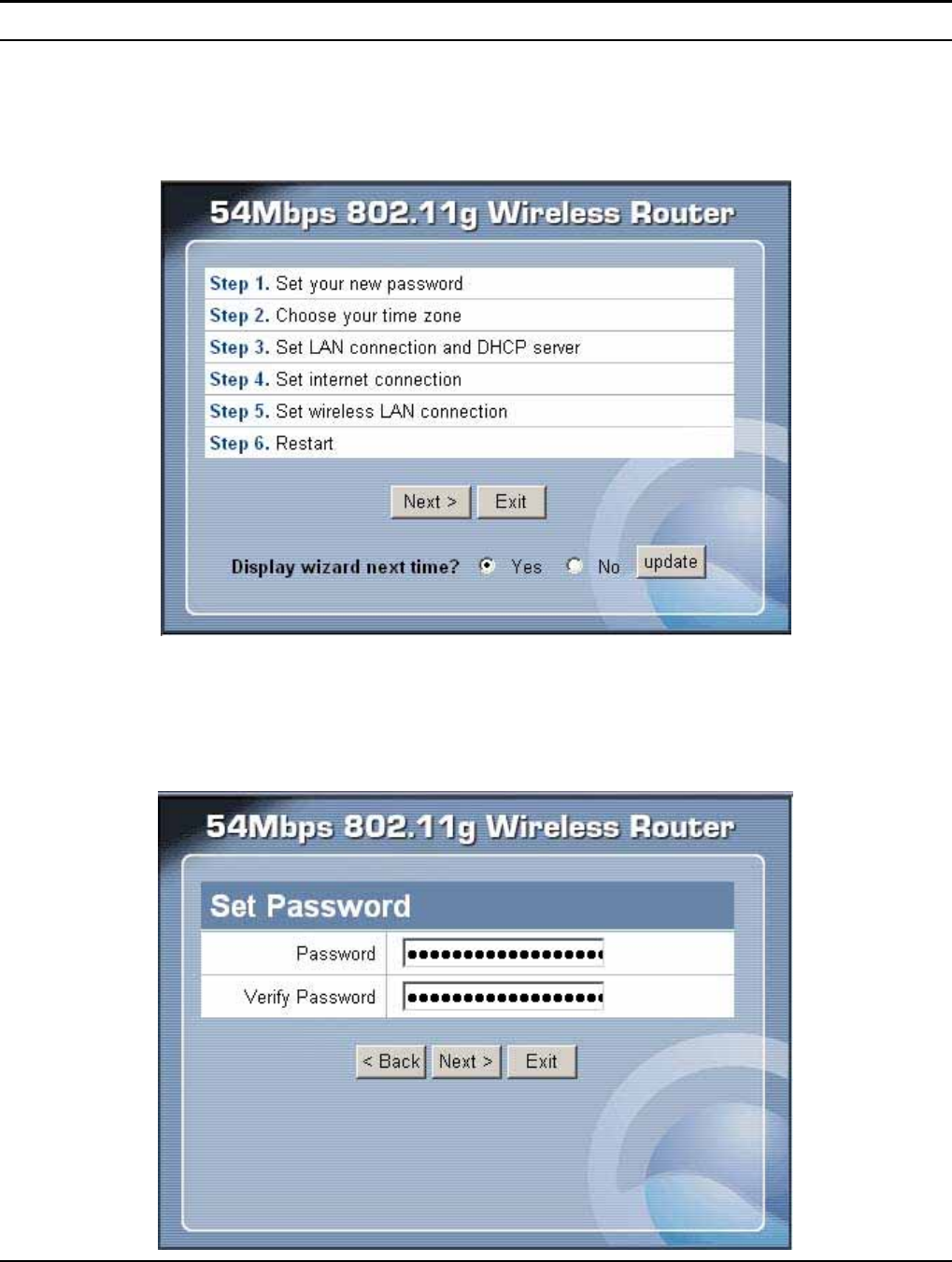
Quick Setup
Setup wizard is provided as the part of the web configuration utility. User can
simply follow the step-by-step process to get the wireless router configuration
ready to run in 6 easy steps by clicking on the “Wizard” button on the function
menu. The following screen will appear. Please click “Next” to continue.
Step 1: Set up new Password
User can change the password and then click “Next” to continue.
14
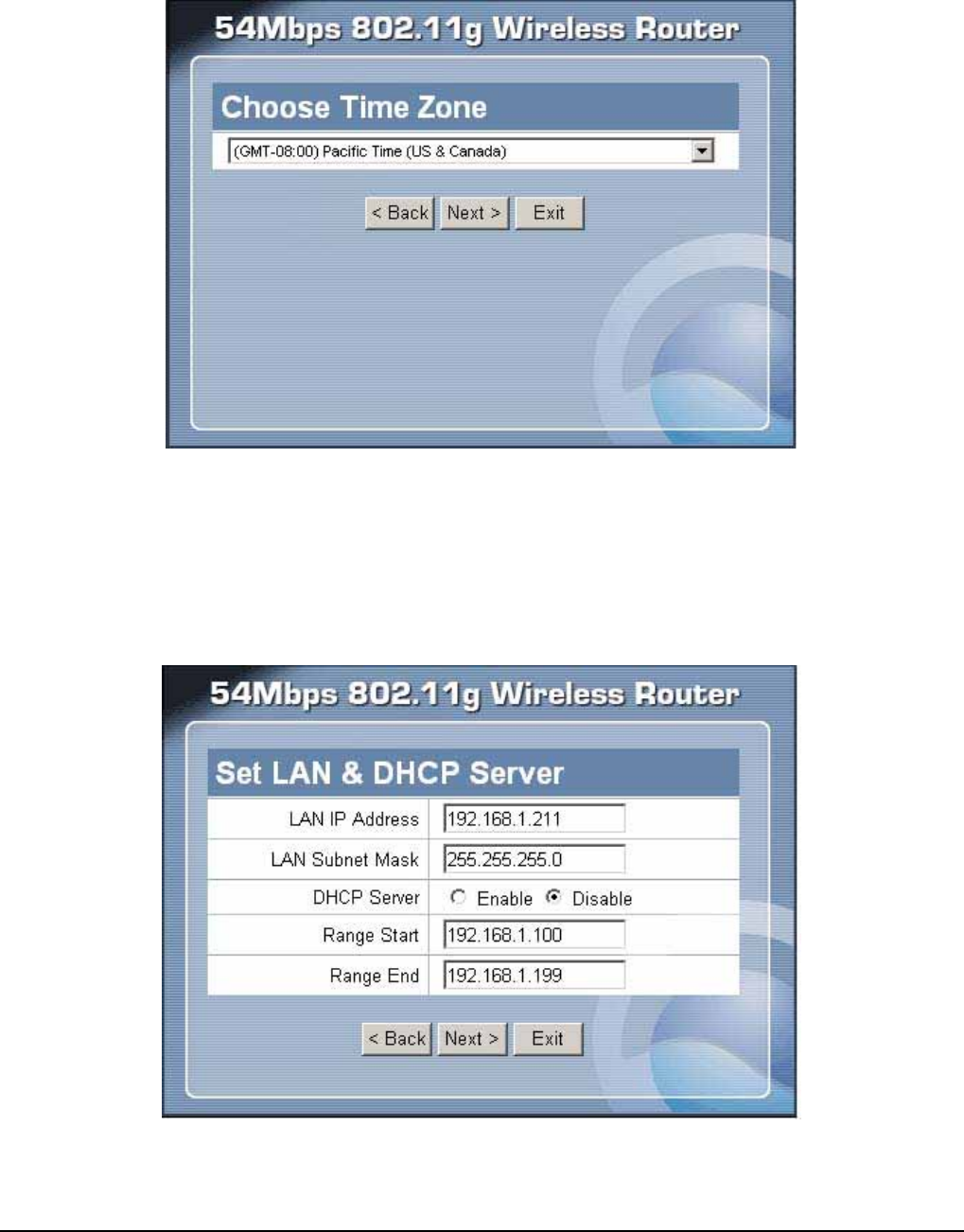
Step 2: Choose time zone
Select the time zone from the drop down list. Please click “Next” to continue.
Step 3: Set LAN connection and DHCP server
Set user’s IP address and mask. The default IP is 192.168.1.1. If user likes to enable
DHCP, please click “Enabled”. DHCP enabled is able to automatically assign IP
addresses. Please assign the range of IP addresses in the fields of “Range start” and
“Range end”. Please click “Next” to continue.
15
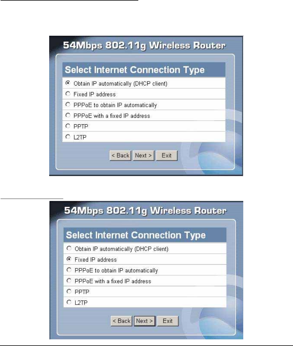
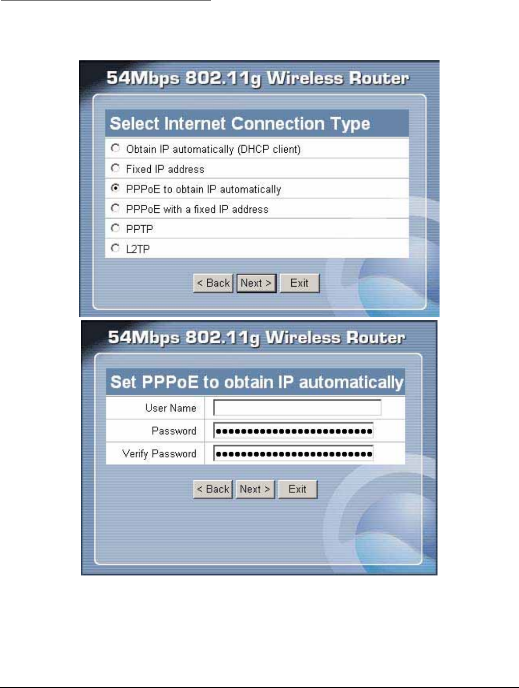
Step 4: Set Internet connection
Select how the router will set up the Internet connection: Obtained IP automatically;
Fixed IP address; PPPoE to obtain IP automatically; PPPoE with a fixed IP address;
PPTP; L2TP.
Obtain IP automatically (DHCP client):
If user has enabled DHCP server, choose "Obtain IP automatically (DHCP client)"
to have the router assign IP addresses automatically.
Fixed IP Address:
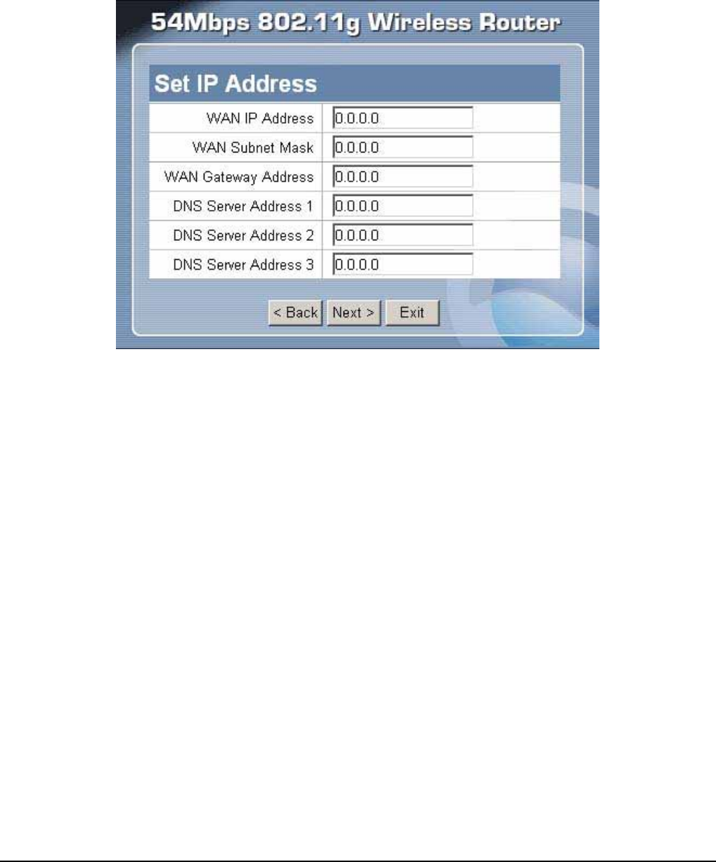
16
If the Internet Service Providers assign a fixed IP address, choose this option and
enter the assigned IP address, subnet mask, gateway IP and DNS IP addresses for
your Broadband Router.
17
PPPoE to obtain IP automatically:
If connected to the Internet using a PPPoE (Dial-up xDSL) Modem, the ISP will
provide a Password and User Name, and then the ISP uses PPPoE. Choose this
option and enter the required information.
18
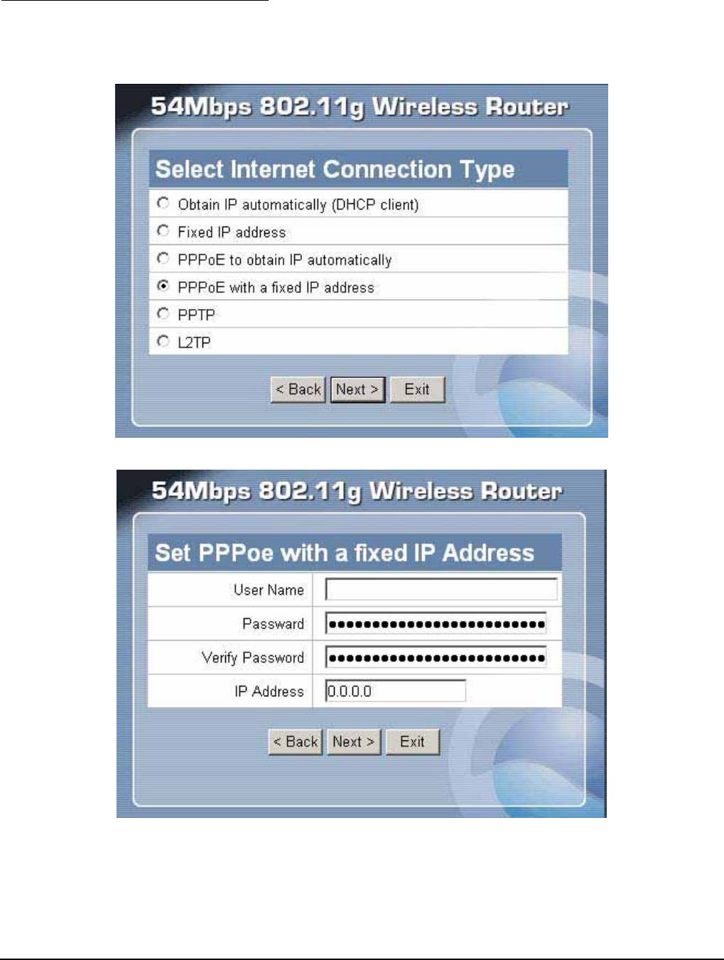
PPPoE with a fixed IP address:
If connected to the Internet using a PPPoE (Dial-up xDSL) Modem, the ISP will
provide a Password, User Name and a Fixed IP Address, choose this option and
enter the required information.
19
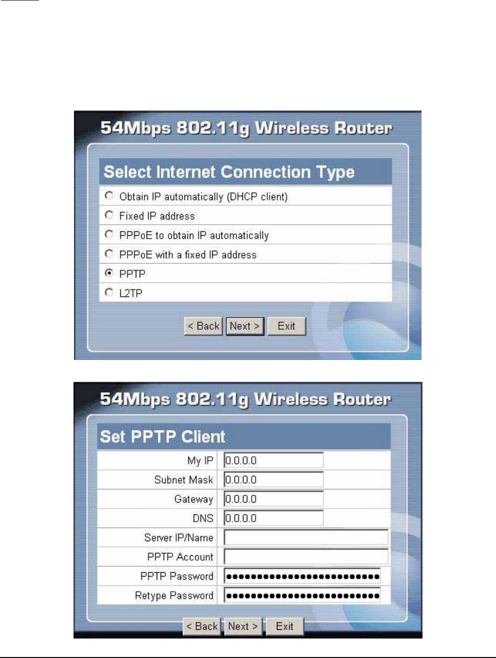
PPTP:
If connected to the Internet using a (PPTP) xDSL Modem, enter the your IP
Address, Subnet Mask, Gateway, Server IP, PPTP Account and PPTP Password,
Your Subnet Mask required by your ISP in the appropriate fields. If your ISP has
provided you with a Connection ID, enter it in the Connection ID field, otherwise,
leave it zero.
20
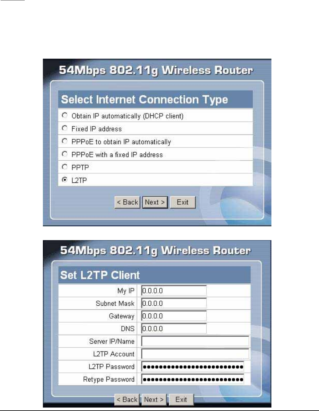
L2TP:
If connected to the Internet using a (L2TP) xDSL Modem, enter the your IP
Address, Subnet Mask, Gateway, Server IP, L2TP Account and L2TP Password,
Your Subnet Mask required by your ISP in the appropriate fields. If your ISP has
provided you with a Connection ID, enter it in the Connection ID field, otherwise,
leave it zero.
21
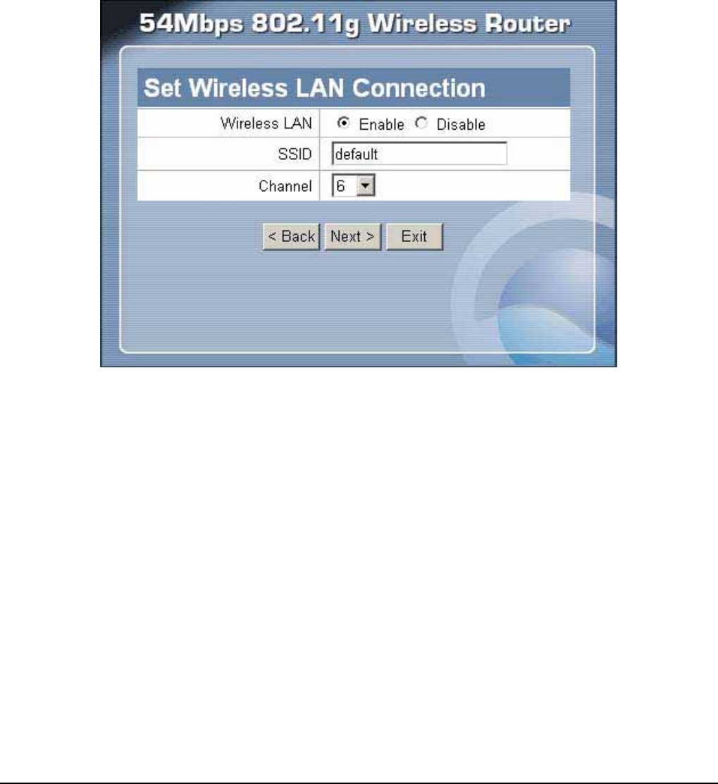
Step 5: Set Wireless LAN connection
Click “Enable” to enable wireless LAN. If user enables the wireless LAN, type the
SSID in the text box and select a communications channel. The SSID and channel
must be the same as wireless devices attempting communication to the router.
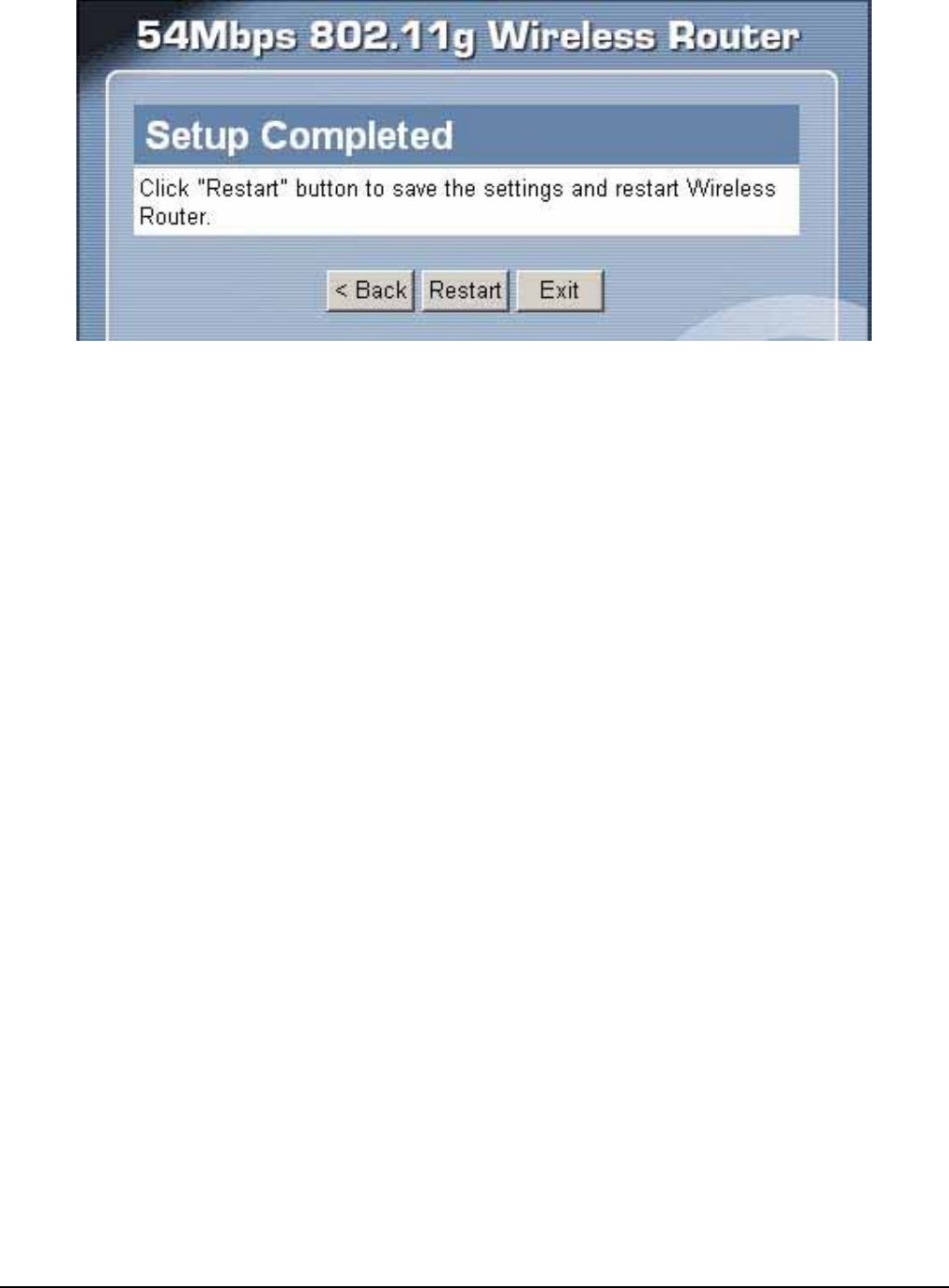
Step 6: Restart
The Setup wizard is now completed. The new settings will be effective after the
Wireless router restarted. Please click “Restart” to reboot the router. If user does
not want to make any changes, please click “Exit” to quit without any changes.
User also can go back to modify the setting by clicking “Back”.
22
23
Advance Setup
2.1 LAN Setting
The screen enables user to configure the LAN & DHCP Server, set WAN
parameters, create Administrator and User passwords, and set the local time, time
zone, and dynamic DNS.
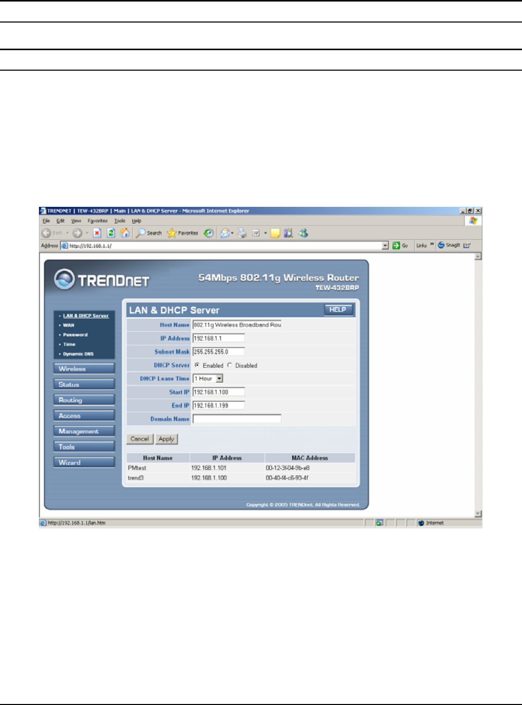
2.1.1 LAN & DHCP Server
This page leads to set LAN and DHCP properties, such as the host name, IP address,
subnet mask, and domain name. LAN and DHCP profiles are listed in the DHCP
table at the bottom of the screen.
Host Name: Type the host name in the text box. The host name is required by some
ISPs. The default host name is "AP-Router."
IP Address: This is the IP address of the router. The default IP address is
192.168.1.1.
Subnet Mask: Type the subnet mask for the router in the text box. The default
subnet mask is 255.255.255.0.
DHCP Server: Enables the DHCP server to allow the router to automatically assign
IP addresses to devices connecting to the LAN. DHCP is enabled by default.
24
All DHCP client computers are listed in the table at the bottom of the screen,
providing the host name, IP address, and MAC address of the client.
Start IP: Type an IP address to serve as the start of the IP range that DHCP will use
to assign IP addresses to all LAN devices connected to the router.
End IP: Type an IP address to serve as the end of the IP range that DHCP will use
to assign IP addresses to all LAN devices connected to the router.
Domain Name: Type the local domain name of the network in the text box. This
item is optional.
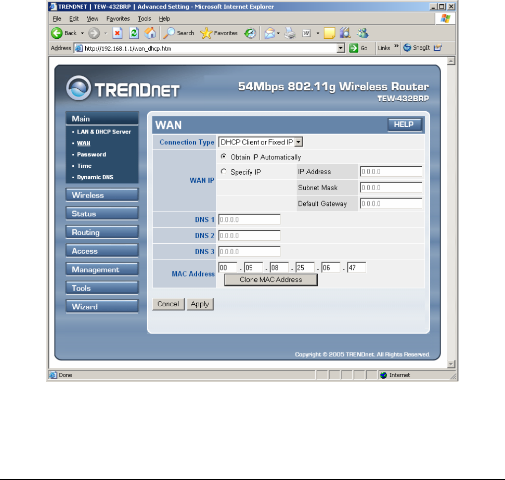
2.1.2 WAN
This screen enables user to set up the router WAN connection, specify the IP
address for the WAN, add DNS numbers, and enter the MAC address.
Connection Type: Select the connection type, either DHCP client, Fixed IP or
PPPoE, PPTP or L2TP from the drop-down list.
WAN IP: Select whether user wants to specify an IP address manually, or want
DHCP to obtain an IP address automatically. When Specify IP is selected, type the
25
IP address, subnet mask, and default gateway in the text boxes. User’s ISP will
provide with this information.
DNS 1/2/3: Type up to three DNS numbers in the text boxes. User’s ISP will
provide with this information.
MAC Address: If required by user’s ISP, type the MAC address of the router WAN
interface in this field.
DNS 1/2/3: Type up to three DNS numbers in the text boxes. User’s ISP will
provide with this information.
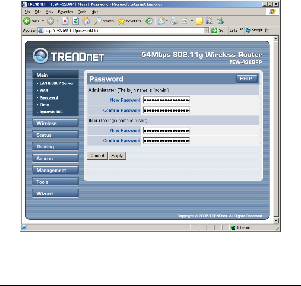
2.1.3 Password
This screen enables user to set administrative and user passwords. These passwords
are used to gain access to the router interface.
Administrator: Type the password the Administrator will use to log in to the system.
The password must be typed again for confirmation.
26
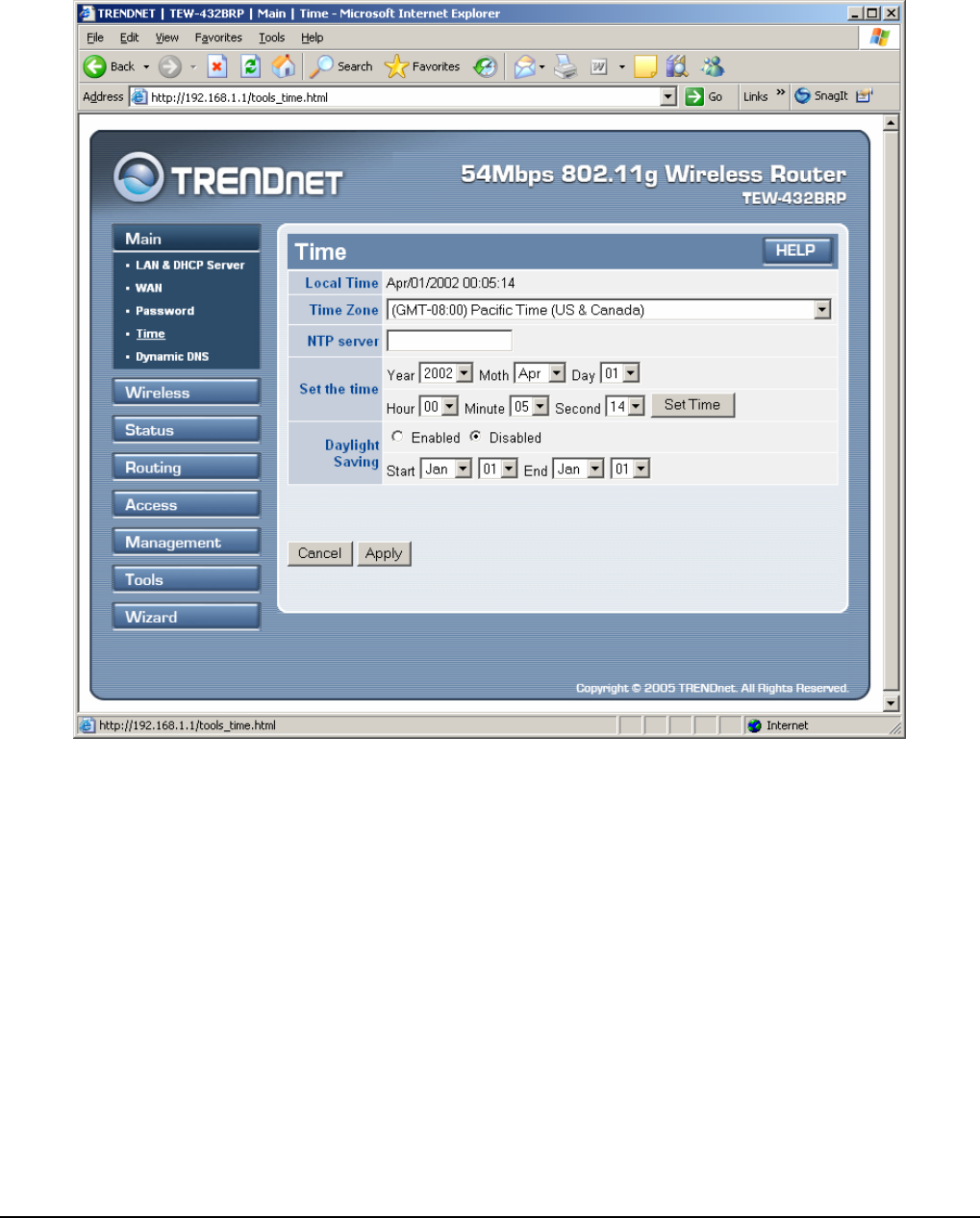
2.1.4 Time
This screen enables user to set the time and date for the router's real-time clock,
select properly time zone, and enable or disable daylight saving.
Local Time: Displays the local time and date.
Time Zone: Select the time zone from the drop-down list.
Daylight Saving: Enables user to enable or disable daylight saving time. When
enabled, select the start and end date for daylight saving time.
27
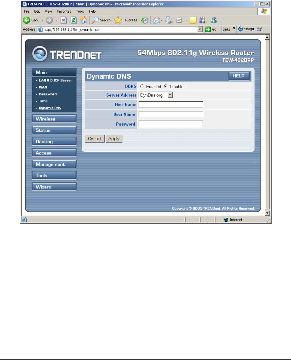
2.1.5 Dynamic DNS
This screen enables user to configure the Dynamic DNS settings.
Select enabled option and enter the Hose Name, User Name, and Password
information from your Dynamic DNS account and click Apply to save the
settings.
28
2.2 Wireless
This section enables user to set wireless communications parameters for the router's
wireless LAN feature.
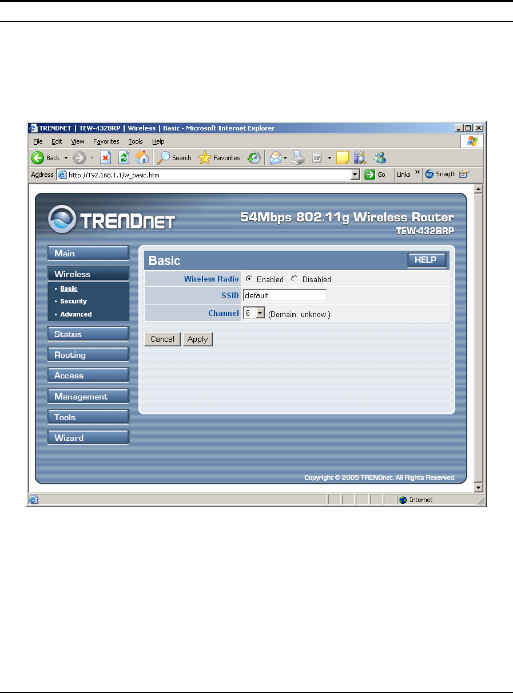
2.2.1 Basic
This page allow user to enable and disable the wireless LAN function, create a
SSID, and select the channel for wireless communications.
Enable/Disable: Enables and disables wireless LAN via the router.
SSID: Type an SSID in the text box. The SSID of any wireless device must match
the SSID typed here in order for the wireless device to access the LAN and WAN
via the router.
Channel: Select a transmission channel for wireless communications. The channel
of any wireless device must match the channel selected here in order for the
wireless device to access the LAN and WAN via the router.
29
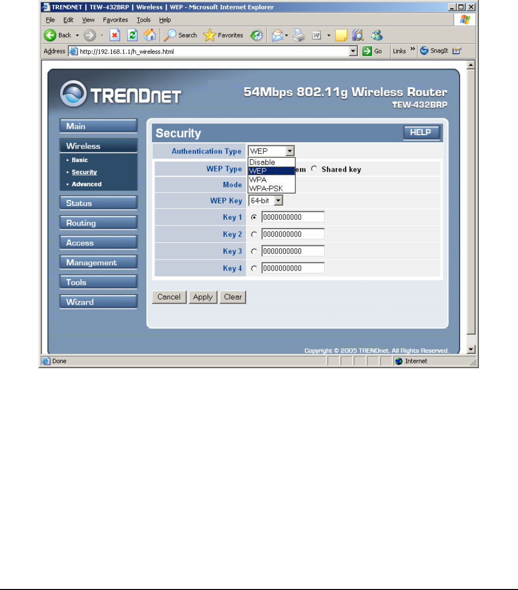
2.2.2 Security
This screen enables user to set authentication type for secure wireless
communications. Open System allows public access to the router via wireless
communications. Shared Key requires the user to set a WEP key to exchange data
with other wireless clients that have the same WEP key. This router also supports
WPA and WPA-PSK.
Authentication Type: The authentication type default is set to Disable.
There are three options: WEP, WPA and WPA-PKS.
WEP Type: Open System or Shared Key
WEP: Enable or Disabled. This is to make WEP enabled or disabled.
Mode: Select the key mode in ASCII or HEX
WEP Key: Select the level of encryption from the drop-down list. The router
supports, 64- and 128-bit encryption.
Key 1 ~ Key 4: Enables user to create an encryption scheme for Wireless LAN
transmissions. Manually enter a set of values for each key. Select a key to use by
clicking the radio button next to the key. Click “Clear” to erase key values.
30
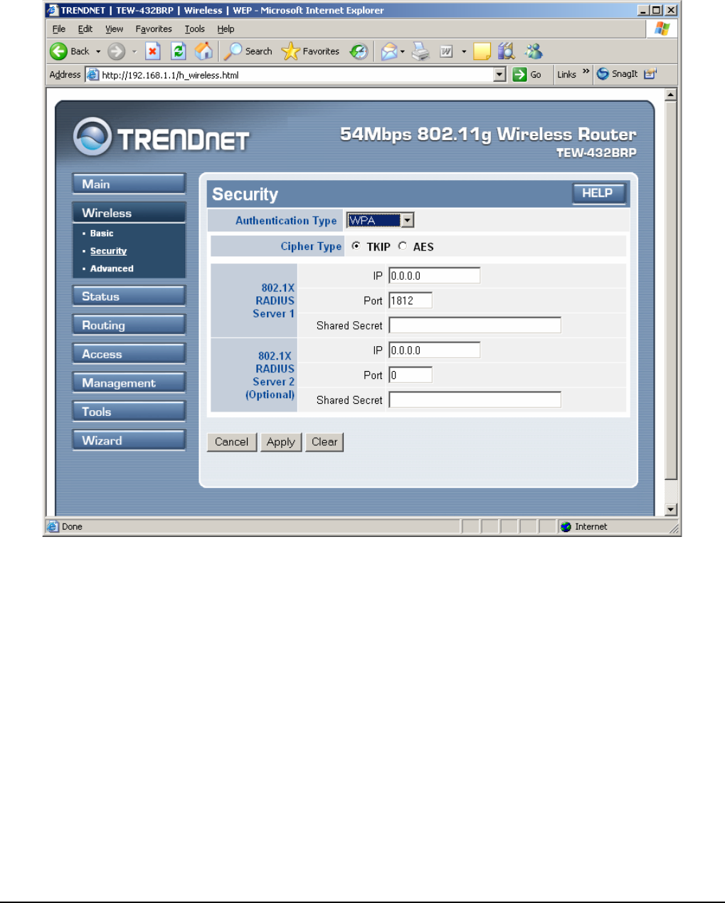
If WPA is selected, the below screen is shown. Please set the length of the
encryption key and the parameters for the RADIUS server.
RADIUS Server:
1. Enter the IP address of and the Port used by the Primary Radius Server
Enter the Shared Secret, which is used by the Radius Server.
2. Enter the IP address of, Port and Shared Secret used by the Secondary Radius
Server.