TRENDNET TEW436BRM 54Mbps Wireless G ADSL 2/2+ Modem Router User Manual UG TEW 436BRM 1 0R
TRENDNET, Inc. 54Mbps Wireless G ADSL 2/2+ Modem Router UG TEW 436BRM 1 0R
TRENDNET >
Contents
- 1. Manual Part 1
- 2. Manual Part 2
Manual Part 1
i

ii
Regulatory notes and statements
Wireless LAN, Health and Authorization for use
Radio frequency electromagnetic energy is emitted from Wireless LAN devices. The energy levels of these
emissions however are far much less than the electromagnetic energy emissions from wireless devices like for
example mobile phones. Wireless LAN devices are safe and have to comply with RF exposure standard and
relevant recommendations. The use of Wireless LAN devices may be restricted in some situations or
environments for example:
·Onboard airplanes, or
·In an explosive environment, or
·In case the interference risk to other devices or services is perceived or identified as harmful
In case the policy regarding the use of Wireless LAN devices in specific organizations or environments (e.g.
airports, hospitals, chemical/oil/gas industrial plants, private buildings etc.) is not clear, please ask for
authorization to use these devices prior to operating the equipment.
Regulatory Information/disclaimers
Installation and use of this Wireless LAN device must be in strict accordance with the instructions included in
the user documentation provided with the product. Any changes or modifications made to this device that are
not exclickly approved by the manufacturer may void the user’s authority to operate the equipment. The
Manufacturer is not responsible for any radio or television interference caused by unauthorized modification of
this device, of the substitution or attachment. Manufacturer and its authorized resellers or distributors will
assume no liability for any damage or violation of government regulations arising from failing to comply with
these guidelines.
FCC statement
Federal Communication Commission Interference Statement
This equipment has been tested and found to comply with the limits for a Class B digital device, pursuant to Part 15 of the FCC Rules.
These limits are designed to provide reasonable protection against harmful interference in a residential installation. This equipment
generates, uses and can radiate radio frequency energy and, if not installed and used in accordance with the instructions, may cause
harmful interference to radio communications. However, there is no guarantee that interference will not occur in a particular
installation. If this equipment does cause harmful interference to radio or television reception, which can be determined by turning
the equipment off and on, the user is encouraged to try to correct the interference by one of the following measures:
- Reorient or relocate the receiving antenna.
- Increase the separation between the equipment and receiver.
- Connect the equipment into an outlet on a circuit different from that to which the receiver is connected.
- Consult the dealer or an experienced radio/TV technician for help.
FCC Caution: Any changes or modifications not expressly approved by the party responsible for compliance could void the user's
authority to operate this equipment.
This device complies with Part 15 of the FCC Rules. Operation is subject to the following two conditions: (1) This device may not
cause harmful interference, and (2) this device must accept any interference received, including interference that may cause undesired
operation.
IMPORTANT NOTE:
FCC Radiation Exposure Statement:
This equipment complies with FCC radiation exposure limits set forth for an uncontrolled environment. This equipment should be
installed and operated with minimum distance 20cm between the radiator & your body.
This transmitter must not be co-located or operating in conjunction with any other antenna or transmitter.
The availability of some specific channels and/or operational frequency bands are country dependent and are firmware programmed at
the factory to match the intended destination. The firmware setting is not accessible by the end user.

iii
PART 68 statement
This equipment complies with Part 68 of FCC Rules and the requirements adopted by the ACTA.. On the bass unit of this equipment
is a label that contains, among other information, a product identifier in the format US: TI1DL01BTEW436BRM. If requested, this
number must be provided to the telephone company. The REN for this product is part of the product identifier that has the format US:
TI1DL01BTEW436BRM. The digits represented by 01 are the REN without a decimal point.
The REN is useful to determine the quantity of devices you may connect to your telephone line and still have those devices ring when
your telephone number is called. In most, but not all areas, the sum of the REN of all devices connected to one line should not exceed
five (5.0). To be certain of the number of devices you may connect to your line, as determined by the REN, you should contact your
local telephone company to determine the maximum REN for your calling area.
If your equipment causes harm to the telephone network, the telephone company may discontinue your service temporarily. If
possible, they will notify you in advance. If advance notice is not practical, you will be notified as soon as possible. You will be
informed of your right to file a complaint with the FCC. Your telephone company may make changes in its facilities, equipment,
operations or procedures that could affect the proper functioning of your equipment. If they do, you will be notified in advance to give
you an opportunity to maintain uninterrupted telephone service.
If you experience trouble with this telephone equipment, please contact the following address and phone number for information on
obtaining service or repairs:
The telephone company may ask that you disconnect this equipment from the network until the problem has been corrected or until
you are sure that the equipment is not malfunctioning.
This equipment may not be used on coin service provided by the telephone company. Connection to party lines is subject to state
tariffs.
CE statement
Europe – EU Declaration of Conformity
This device complies with the essential requirements of the R&TTE Directive 1999/5/EC. The following test methods have been
applied in order to prove presumption of conformity with the essential requirements of the R&TTE Directive 1999/5/EC:
EN60950-1: 2006
Safety of Information Technology Equipment
EN 50385: 2002
Product standard to demonstrate the compliance of radio base stations and fixed terminal stations for wireless telecommunication
systems with the basic restrictions or the reference levels related to human exposure to radio frequency electromagnetic fields
(110MHz - 40 GHz) - General public
EN 300 328 V1.7.1 (2006-10)
Electromagnetic compatibility and Radio spectrum Matters (ERM); Wideband transmission systems; Data transmission equipment
operating in the 2,4 GHz ISM band and using wide band modulation techniques; Harmonized EN covering essential requirements
under article 3.2 of the R&TTE Directive
EN 301 489-1 V1.8.1 (2008-04)
Electromagnetic compatibility and Radio Spectrum Matters (ERM); ElectroMagnetic Compatibility (EMC) standard for radio
equipment and services; Part 1: Common technical requirements
EN 301 489-17 V1.3.2 (2008-04)
Electromagnetic compatibility and Radio spectrum Matters (ERM); ElectroMagnetic Compatibility (EMC) standard for radio
equipment and services; Part 17: Specific conditions for 2,4 GHz wideband transmission systems , 5 GHz high performance RLAN
equipment and 5,8GHz Broadband Data Transmitting Systems.
This device is a 2.4 GHz wideband transmission system (transceiver), intended for use in all EU member states and EFTA countries,
except in France and Italy where restrictive use applies.
In Italy the end-user should apply for a license at the national spectrum authorities in order to obtain authorization to use the device
for setting up outdoor radio links and/or for supplying public access to telecommunications and/or network services.
This device may not be used for setting up outdoor radio links in France and in some areas the RF output power may be limited to 10
mW EIRP in the frequency range of 2454 – 2483.5 MHz. For detailed information the end-user should contact the national spectrum
authority in France.

iv
Česky [Czech] TRENDnet tímto prohlašuje, že tento TEW-436BRM je ve shodě se základními požadavky a dalšími příslušnými
ustanoveními směrnice 1999/5/ES.
Dansk [Danish] Undertegnede TRENDnet erklærer herved, at følgende udstyr TEW-436BRM overholder de væsentlige krav og
øvrige relevante krav i direktiv 1999/5/EF.
Deutsch [German] Hiermit erklärt TRENDnet , dass sich das Gerät TEW-436BRM in Übereinstimmung mit den grundlegenden
Anforderungen und den übrigen einschlägigen Bestimmungen der Richtlinie 1999/5/EG befindet.
Eesti [Estonian] Käesolevaga kinnitab TRENDnet seadme TEW-436BRM vastavust direktiivi 1999/5/EÜ põhinõuetele ja
nimetatud direktiivist tulenevatele teistele asjakohastele sätetele.
English Hereby, TRENDnet , declares that this TEW-436BRM is in compliance with the essential requirements and other
relevant provisions of Directive 1999/5/EC.
Español [Spanish] Por medio de la presente TRENDnet declara que el TEW-436BRM cumple con los requisitos esenciales y
cualesquiera otras disposiciones aplicables o exigibles de la Directiva 1999/5/CE.
Ελληνική [Greek] ΜΕ ΤΗΝ ΠΑΡΟΥΣΑ TRENDnet ∆ΗΛΩΝΕΙ ΟΤΙTEW-436BRM ΣΥΜΜΟΡΦΩΝΕΤΑΙ ΠΡΟΣ ΤΙΣ
ΟΥΣΙΩ∆ΕΙΣ ΑΠΑΙΤΗΣΕΙΣ ΚΑΙ ΤΙΣ ΛΟΙΠΕΣ ΣΧΕΤΙΚΕΣ ∆ΙΑΤΑΞΕΙΣ ΤΗΣ Ο∆ΗΓΙΑΣ 1999/5/ΕΚ.
Français [French] Par la présente TRENDnet déclare que l'appareil TEW-436BRM est conforme aux exigences essentielles et aux
autres dispositions pertinentes de la directive 1999/5/CE.
Italiano [Italian] Con la presente TRENDnet dichiara che questo TEW-436BRM è conforme ai requisiti essenziali ed alle altre
disposizioni pertinenti stabilite dalla direttiva 1999/5/CE.
Latviski [Latvian] Ar šo TRENDnet deklarē, ka TEW-436BRM atbilst Direktīvas 1999/5/EK būtiskajām prasībām un citiem ar to
saistītajiem noteikumiem.
Lietuvių [Lithuanian]
Šiuo TRENDnet deklaruoja, kad šis TEW-436BRM atitinka esminius reikalavimus ir kitas 1999/5/EB Direktyvos
nuostatas.
Nederlands [Dutch] Hierbij verklaart TRENDnet dat het toestel TEW-436BRM in overeenstemming is met de essentiële eisen en de
andere relevante bepalingen van richtlijn 1999/5/EG.
Malti [Maltese] Hawnhekk, TRENDnet , jiddikjara li dan TEW-436BRM jikkonforma mal-ħtiġijiet essenzjali u ma provvedimenti
oħrajn relevanti li hemm fid-Dirrettiva 1999/5/EC.
Magyar [Hungarian] Alulírott, TRENDnet nyilatkozom, hogy a TEW-436BRM megfelel a vonatkozó alapvetõ követelményeknek és
az 1999/5/EC irányelv egyéb elõírásainak.
Polski [Polish] Niniejszym TRENDnet oświadcza, że TEW-436BRM jest zgodny z zasadniczymi wymogami oraz pozostałymi
stosownymi postanowieniami Dyrektywy 1999/5/EC.
Português [Portuguese]
TRENDnet declara que este TEW-436BRM está conforme com os requisitos essenciais e outras disposições da
Directiva 1999/5/CE.
Slovensko [Slovenian]
TRENDnet izjavlja, da je ta TEW-436BRM v skladu z bistvenimi zahtevami in ostalimi relevantnimi določili
direktive 1999/5/ES.
Slovensky [Slovak] TRENDnet týmto vyhlasuje, že TEW-436BRM spĺňa základné požiadavky a všetky príslušné ustanovenia
Smernice 1999/5/ES.
Suomi [Finnish] TRENDnet vakuuttaa täten että TEW-436BRM tyyppinen laite on direktiivin 1999/5/EY oleellisten vaatimusten
ja sitä koskevien direktiivin muiden ehtojen mukainen.
Svenska [Swedish] Härmed intygar TRENDnet att denna TEW-436BRM står I överensstämmelse med de väsentliga egenskapskrav
och övriga relevanta bestämmelser som framgår av direktiv 1999/5/EG.
0560

v
TABLE OF CONTENT
A
BOUT
T
HIS
G
UIDE
....................................................................................1
Purpose.................................................................................................................................................................................................. 1
Terms/Usage ......................................................................................................................................................................................... 1
Overview of this User’s Guide.............................................................................................................................................................. 1
I
NTRODUCTION
...........................................................................................2
Applications:......................................................................................................................................................................................... 2
Supported Features: .............................................................................................................................................................................. 2
Wireless Performance Considerations .................................................................................................................................................. 3
U
NPACKING AND
S
ETUP
.............................................................................4
Unpacking............................................................................................................................................................................................. 4
Setup ..................................................................................................................................................................................................... 4
H
ARDWARE
I
NSTALLATION
........................................................................5
Front Panel............................................................................................................................................................................................ 5
LED Indicators...................................................................................................................................................................................... 5
Rear Panel............................................................................................................................................................................................. 7
Hardware connections........................................................................................................................................................................... 8
Connecting the WLAN ADSL Router .............................................................................................................................................. 8
Check the installation........................................................................................................................................................................ 8
PC
N
ETWORK
TCP/IP
S
ETTING
.................................................................9
Windows 95/98/ME.............................................................................................................................................................................. 9
Windows 2000 .................................................................................................................................................................................... 10
Windows XP / Vista............................................................................................................................................................................ 11
C
ONFIGURATION
......................................................................................12
Login to the WLAN ADSL Router through Wireless LAN................................................................................................................ 12
Login to the WLAN ADSL Router..................................................................................................................................................... 12
Using the Web Browser ...................................................................................................................................................................... 12
Configuration Menu............................................................................................................................................................................ 14
S
ETUP
W
IZARD
.........................................................................................15
Step 1: Determine Connection Method............................................................................................................................................... 15
Step 2: ADSL Setting.......................................................................................................................................................................... 16
Step 3: Select Channel Mode.............................................................................................................................................................. 16
Step 4: Completed the Setup Wizard .................................................................................................................................................. 28
M
ANUAL
S
ETINGS
....................................................................................29
Status................................................................................................................................................................................................... 29
Setup ................................................................................................................................................................................................... 29
Internet Setup.................................................................................................................................................................................. 29
LAN Setup...................................................................................................................................................................................... 31
Wireless .......................................................................................................................................................................................... 32
DHCP Settings................................................................................................................................................................................ 38
Time Zone....................................................................................................................................................................................... 40
Firewall – Used only on Router mode settings ................................................................................................................................... 41
IP/Port Filtering .............................................................................................................................................................................. 41
MAC Filtering................................................................................................................................................................................. 42

vi
Port Forwarding .............................................................................................................................................................................. 43
URL Blocking................................................................................................................................................................................. 45
Domain Blocking............................................................................................................................................................................ 46
Port Triggering................................................................................................................................................................................ 47
DMZ................................................................................................................................................................................................ 48
Advance – Used only on Router mode settings .................................................................................................................................. 49
Wireless .......................................................................................................................................................................................... 49
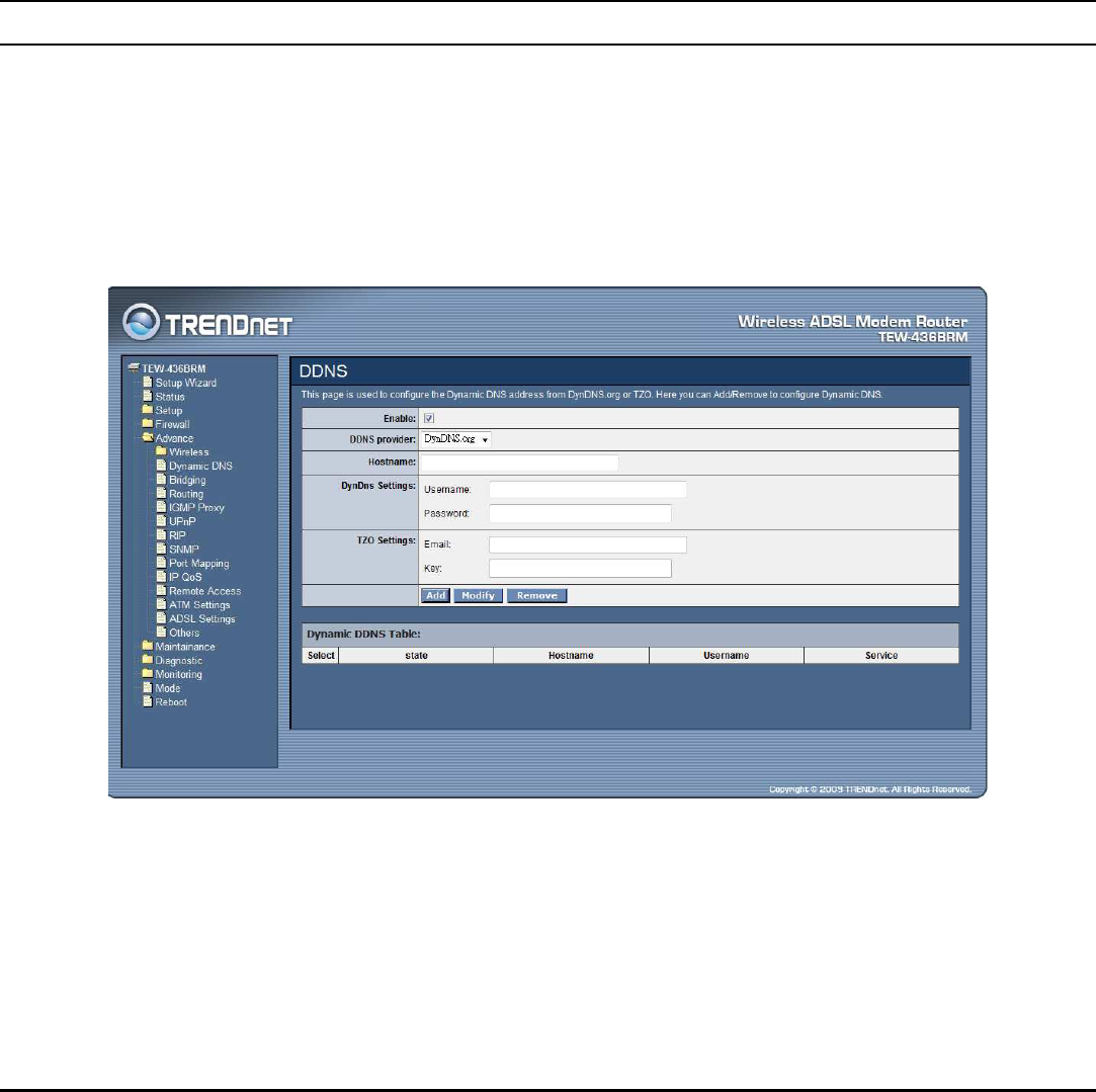
Dynamic DNS................................................................................................................................................................................. 53
Bridging .......................................................................................................................................................................................... 55
Routing............................................................................................................................................................................................ 56
IGMP Proxy.................................................................................................................................................................................... 58
UPnP............................................................................................................................................................................................... 58
RIP .................................................................................................................................................................................................. 59
SNMP.............................................................................................................................................................................................. 60
Port Mapping .................................................................................................................................................................................. 61
IP QoS............................................................................................................................................................................................. 62
Remote Access................................................................................................................................................................................ 63
ATM Settings.................................................................................................................................................................................. 64
ADSL Settings ................................................................................................................................................................................ 65
Maintainance....................................................................................................................................................................................... 67
Backup/Restore............................................................................................................................................................................... 67
Password ......................................................................................................................................................................................... 67
Upgrade Firmware .......................................................................................................................................................................... 69
Access Controls .............................................................................................................................................................................. 70
TR-069 Config................................................................................................................................................................................ 71
Logout............................................................................................................................................................................................. 72
Diagnostic ........................................................................................................................................................................................... 73
Ping................................................................................................................................................................................................. 73
ATM Loopback............................................................................................................................................................................... 74
ADSL.............................................................................................................................................................................................. 75
Diagnostic Test ............................................................................................................................................................................... 75
Monitoring .......................................................................................................................................................................................... 76
DHCP Clients.................................................................................................................................................................................. 76
Routing Table.................................................................................................................................................................................. 76
ARP Table....................................................................................................................................................................................... 77
Bridge FDB Table........................................................................................................................................................................... 77
Interface Statistics........................................................................................................................................................................... 78
ADSL Statistics............................................................................................................................................................................... 78
Mode................................................................................................................................................................................................... 79
Reboot................................................................................................................................................................................................. 80
T
ECHNICAL
S
PECIFICATIONS
...................................................................81
L
IMITED
W
ARRANTY
................................................................................83

1
ABOUT THIS GUIDE
Congratulations on your purchase of this 54Mbps Wireless G 2/2+ ADSL Modem
Router. This integrated access device combines ADSL modem, Internet gateway
functions with wireless LAN and Fast Ethernet switch. It provides a complete
solution for Internet surfing and office resource sharing, and it is easy to configure
and operate for every user.
Purpose
This manual discusses how to install the IEEE 54Mbps Wireless G 2/2+ ADSL
Modem Router.
Terms/Usage
In this guide, the term “the WLAN ADSL Router” refers to your 54Mbps Wireless
G 2/2+ ADSL Modem Router.
Overview of this User’s Guide
Introduction. Describes the 54Mbps Wireless G 2/2+ ADSL Modem Router and
its features.
Unpacking and Setup. Helps you get started with the basic installation of the
54Mbps Wireless G 2/2+ ADSL Modem Router.
Identifying External Components. Describes the front panel, rear panel and LED
indicators of the 54Mbps Wireless G 2/2+ ADSL Modem Router.
Connecting the WLAN ADSL Router. Tells how you can connect the 54Mbps
Wireless G 2/2+ ADSL Modem Router.
Technical Specifications. Lists the technical (general, physical and environmental,
performance and Routers settings) specifications of the 54Mbps Wireless G 2/2+
ADSL Modem Router.

2
INTRODUCTION
The 54Mbps Wireless G ADSL 2/2+ Modem Router (model TEW-436BRM) is an
all-in-one modem and wireless g router.
No need to buy a separate modem and router. This sleek device provides an ADSL
2/2+ modem, wireless g router and 4-port switch, all in a single product.
Quickly install this device to surf the Internet, download files, play games and talk
Online. Advanced wireless encryption, a double firewall and a wireless on/off
switch protect your valuable data. Wi-Fi Protected Setup (WPS) allows users to
securely synchronize WPS supported wireless peripheral devices at the touch of a
button.
Applications:
Broadband Internet access:
Several computers can share one high-speed broadband connection through
wireless or wired (WLAN, LAN and WAN-Internet).
Resource sharing:
Share resources such as printers, scanners and other peripherals.
File sharing:
Exchange data, messages, and distribute files thus making good use of hard disk
space.
Online gaming:
Through the local area network, online gaming and e-commerce services can be
easily setup.
Firewall:
A built-in firewall function — for security and anti-hacking systems.
Supported Features:
Compliant with ADSL G.dmt (G.992.1), G.lite (G.992.2) standards and
Compliant with ADSL2 G.dmt.bis (G.992.3) & ADSL2+ G.992.5 standards
Up to 24Mbps downstream, 1.2Mbps upstream with ADSL2+ service
IEEE 802.11b/g Infrastructure operating modes
Supports TR069 remote management, Web based configuration and Command
Line Interface (CLI) via Telnet
Supports NAT, DHCP
Supports VLAN and QoS
Supports up to 8 PVCs
Supports 64/128-bit WEP, WPA/WPA2 and WPA-PSK/WPA2-PSK
Supports Wi-Fi Protected Setup (WPS) for easy connection

3
Wireless Performance Considerations
There are a number of factors that can impact the range of wireless devices.
1. Adjust your wireless devices so that the signal is traveling in a straight path,
rather than at an angle. The more material the signal has to pass through the
more signal you will lose.
2. Keep the number of obstructions to a minimum. Each obstruction can reduce the
range of a wireless device. Position the wireless devices in a manner that will
minimize the amount of obstructions between them.
3. Building materials can have a large impact on your wireless signal. In an indoor
environment, try to position the wireless devices so that the signal passes
through less dense material such as dry wall. Dense materials like metal, solid
wood, glass or even furniture may block or degrade the signal.
4. Antenna orientation can also have a large impact on your wireless signal. Use
the wireless adapter’s site survey tool to determine the best antenna orientation
for your wireless devices.
5. Interference from devices that produce RF (radio frequency) noise can also
impact your signal. Position your wireless devices away from anything that
generates RF noise, such as microwaves, radios and baby monitors.
6. Any device operating on the 2.4GHz frequency will cause interference. Devices
such as 2.4GHz cordless phones or other wireless remotes operating on the
2.4GHz frequency can potentially drop the wireless signal. Although the phone
may not be in use, the base can still transmit wireless signal. Move the phone’s
base station as far away as possible from your wireless devices.
If you are still experiencing low or no signal consider repositioning the wireless
devices or installing additional access points. The use of higher gain antennas may
also provide the necessary coverage depending on the environment.

4
UNPACKING AND SETUP
This chapter provides unpacking and setup information for the 54Mbps Wireless G
2/2+ ADSL Modem Router.
Unpacking
Open the box of the WLAN ADSL Router and carefully unpack it. The box should
contain the following items:
TEW-436BRM 54Mbps Wireless G 2/2+ ADSL Modem Router
CD-Rom (User’s Guide)
External power adapter
1 1.5m (5ft) Cat.5 Ethernet Cable
1 RJ-11 (ADSL) cable
If any item is found missing or damaged, please contact your local reseller for
replacement.
Setup
The setup of the WLAN ADSL Router can be performed properly using the
following methods:
The power outlet should be within 1.82 meters (6 feet) of the Broadband Router.
Visually inspect the DC power jack and make sure that it is fully secured to the
power adapter.
Make sure that there is proper heat dissipation and adequate ventilation around
the WLAN ADSL Router. Do not place heavy objects on the WLAN ADSL
Router.
Fix the direction of the antenna. Try to place the WLAN ADSL Router in a
position that can best cover your wireless network. Normally, the higher you
place the antenna, the better the performance will be. The antenna’s position
enhances the receiving sensitivity.
5
HARDWARE INSTALLATION
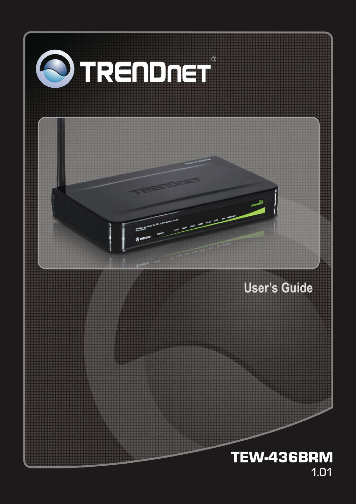
Front Panel
The figure below shows the front panel of the IEEE 802.11b/g Wireless ADSL
Router.
Front Panel
LED Indicators
LED Color State Description
Green Solid on Power on, normal operation.
Red Solid on Power on, self-test failed, indicating device
malfunction.
Power
Off Power off.
Blinking Pending ADSL line synchronization.
DSL Green Solid on ADSL line synchronized.
Blinking Internet activity.
Green Solid on Internet connectivity, no activity.
Red Solid on Internet connection setup failed.
Internet
Off No Internet connection.
Blinking Ethernet activity.
Green Solid on Ethernet connection, no activity. LAN 1~4
Off No Ethernet connection.
Blinking Wireless activity.
WLAN Green Solid on Wireless connection, no activity.

6
Off Wireless disabled.
Blinking WPS in progress.
Green Solid on WPS success.
Red Solid on WPS fail.
WPS
Off WPS disabled.

7
Rear Panel
The figure below shows the rear panel of the IEEE 802.11b/g Wireless ADSL
Router.
Rear Panel
Antenna
One 2dBi gain antenna for wireless connection.
LAN (1-4)
Four RJ-45 10/100Mbps Auto-MDIX ports for connecting to either 10Mbps or
100Mbps Ethernet connections.
DSL (ADSL Port)
Connect to an active telephone line (RJ-11).
DC IN
Receptor for the supplied power adapter.
ON/OFF (On/Off Switch)
Press this button to turn the unit on or off.
WPS Button
Press to enable Wi-Fi Protected Setup.
RESET
Holding the Reset button for 5 seconds restores the WLAN ADSL Router to its
original factory default settings.

8
Hardware connections
Connecting the WLAN ADSL Router
1. Connect ADSL Cable
Connect the supplied RJ-11 ADSL cable from to the DSL port on the Wireless
ADSL Router (the RJ11 connector) to the ADSL terminator provided by your
phone company.
2. Connect LAN Cables
Use standard LAN cables to connect PCs to the LAN ports on the Wireless
ADSL Router.
3. Connect Power
Connect the supplied power adapter to the Wireless ADSL Router. Use only the
power adapter provided. Using a different one may cause hardware damage.
Check the installation
The LEDs on the WLAN ADSL Router are clearly visible and the status of the
network link can be seen instantly:
1. With the power source on, once the device is connected to the phone line and
PCs, the Power, LAN, WLAN and DSL, INETRNET LEDs of the WLAN
ADSL Router will light up indicating a normal status.
2. When the ADSL line is connected the DSL LED will light up.
3. When the Internet is connected the INTERNET LED will light up. (Need to
configuration)
9
PC NETWORK TCP/IP SETTING
The network TCP/IP settings differ based on the computer’s operating system
(Win95/98/ME/NT/2000/XP/Vista) and are as follows.
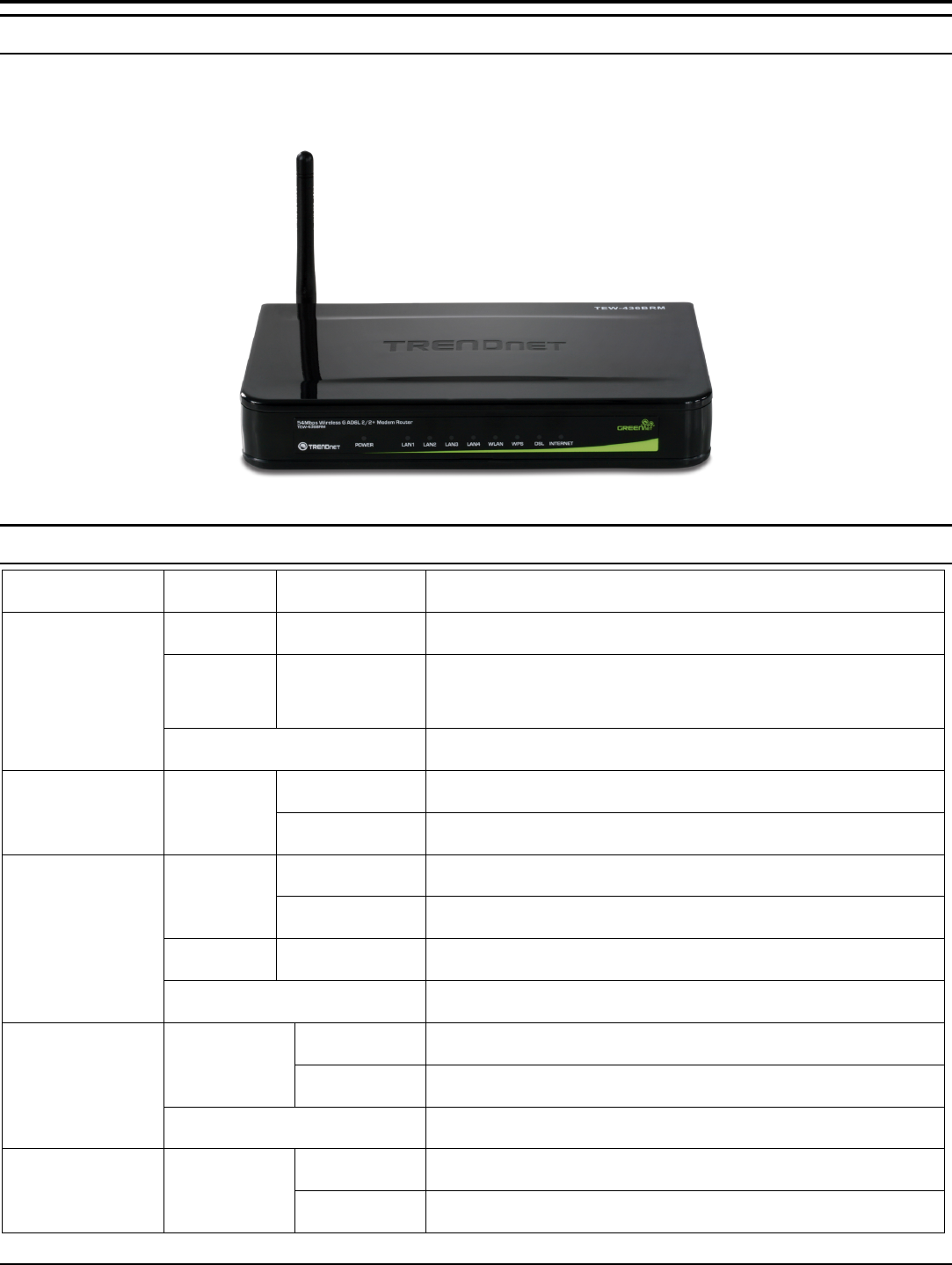
Windows 95/98/ME
1. Click on the “Network neighborhood” icon found on the desktop.
2. Click the right mouse button and a context menu will be show.
3. Select “Properties” to enter the TCP/IP setting screen.
4. Select “Obtain an IP address automatically” on the “IP address” field.
5. Select “Disable DNS” in the “DNS” field.
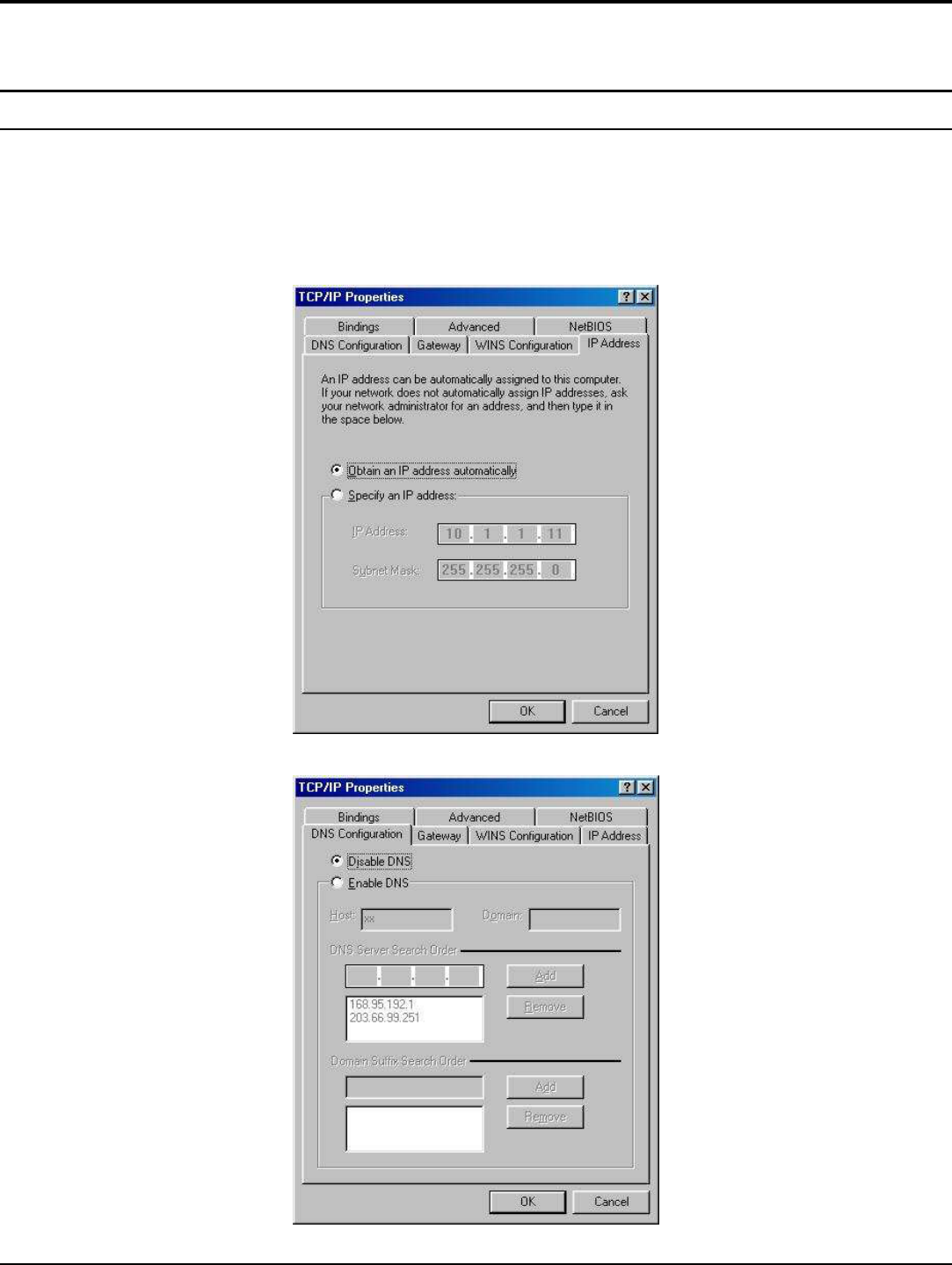
10
6. Select “None” for the “Gateway address” field.
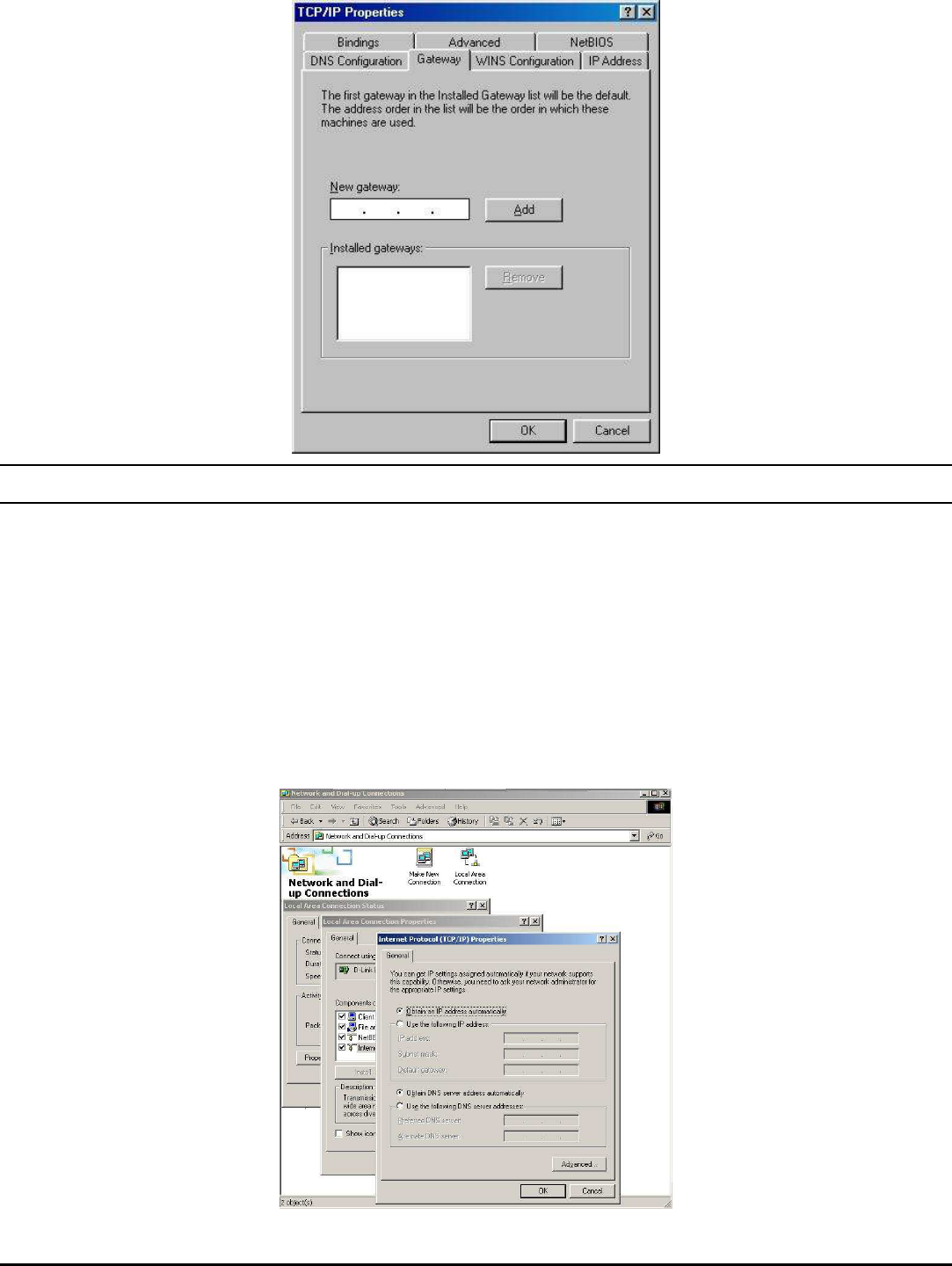
Windows 2000
Double click on the “My Computer” icon on the desktop. When “My Computer”
window opens, open the “Control Panel” and then open the “Network dialup
connection” applet. Double click on the “Local area network connection” icon.
Select “Properties” to enter the TCP/IP setting window.
1. In the “Local area network status” window, click on “Properties.”
2. In the “Local area network connection” window, first select TCP/IP setting
and then select “Properties.”
3. Set both “IP address” and “DNS” to Automatic configuration.
11
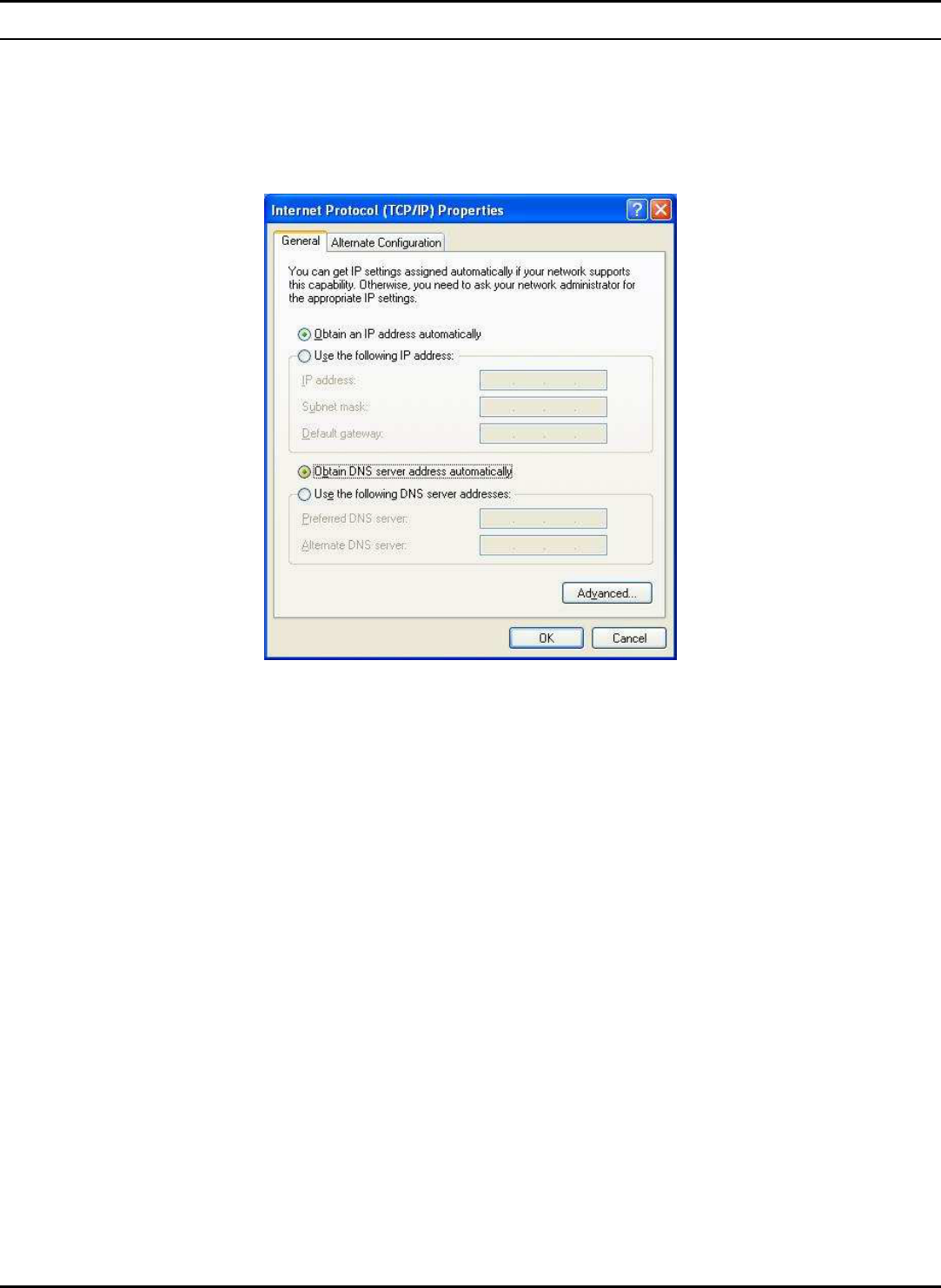
Windows XP / Vista
Point the cursor and click the right button on the “My Network Place” icon.
Select “properties” to enter the TCP/IP setting window.
1. Set “IP address” to “Obtain an IP address automatically.”
2. Set “DNS” to “Obtain DNS server address automatically.”
12
CONFIGURATION
First make sure that the network connections are functioning normally.
This WLAN Router can be configured using Internet Explorer 5.0 or newer web
browser versions.
Login to the WLAN ADSL Router through Wireless LAN
Before configuring the WLAN ADSL Router through WLAN, make sure that the
SSID, Channel and the WEP is set properly.
The default setting of the WLAN ADSL Router that you will use:
SSID: TRENDnet436
Channel: Auto
802.11 Mode: 802.11b+g mixed mode
Security: disable
IP Address: 192.168.10.1
VPI/VCI for ATM: 5/35
ADSL Line mode: Auto-detect
Login to the WLAN ADSL Router
Before you configure this device, note that when the WLAN ADSL Router, make
sure the host PC must be set on the IP subnet that can be accessed by the
xDSL/Cable modem. For example, when the default network address of the
xDSL/Cable modem Ethernet interface is 192.168.10.x, then the host PC should be
set at 192.168.10.xxx (where xxx is a number between 2 and 254), and the default
subnet mask is 255.255.255.0.
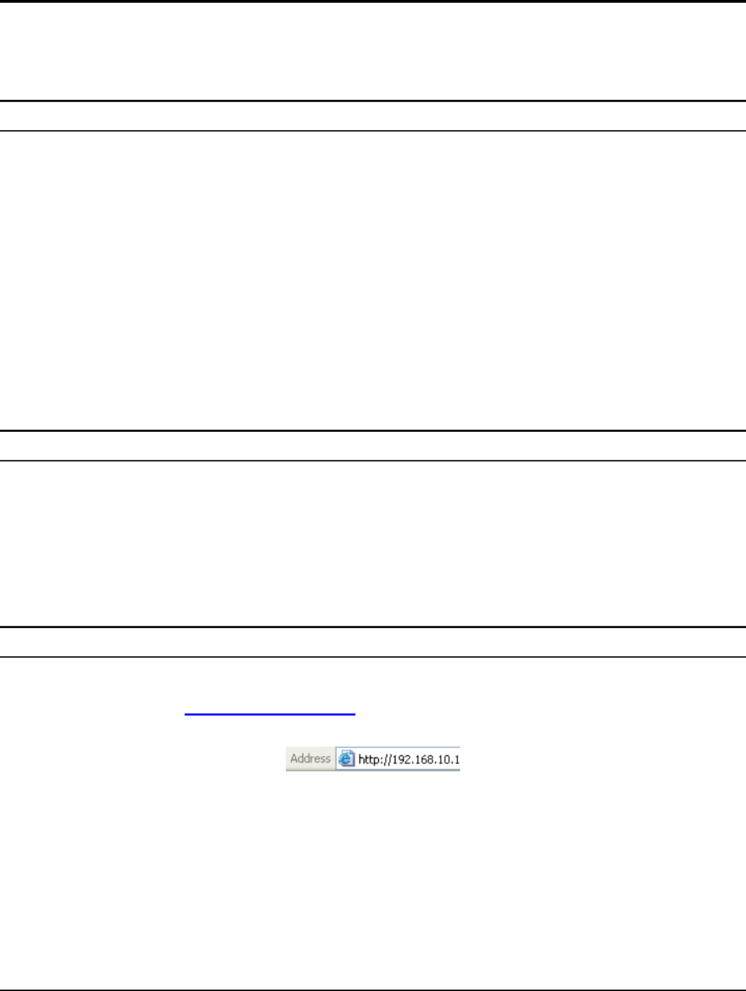
Using the Web Browser
1. Open Internet Explorer 6.0 or above Internet browser.
2. Enter IP address http://192.168.10.1 (the factory-default IP address setting) to
the URL web address location.
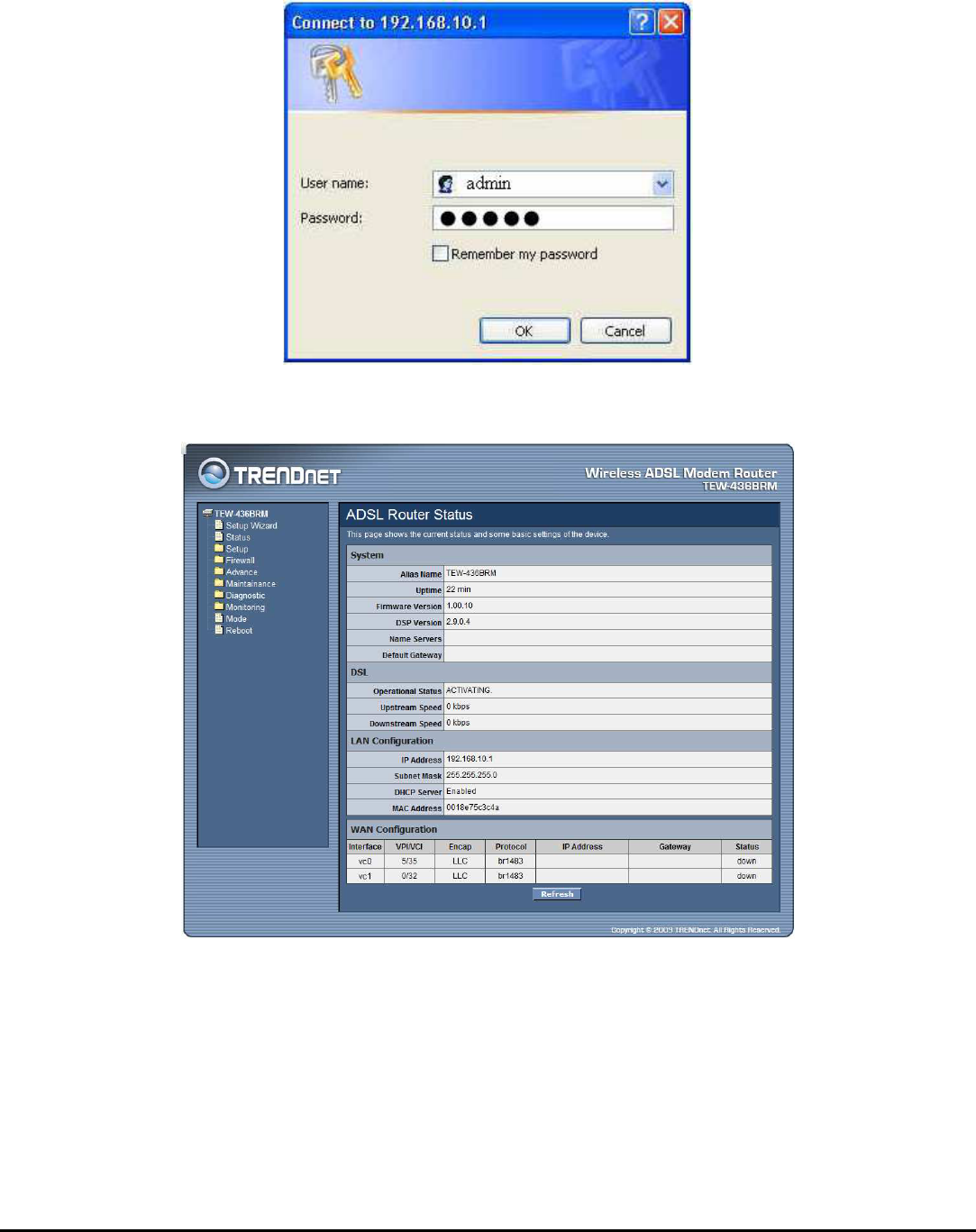
13
3. When the following dialog box appears, enter the user name and password to
login to the main configuration window, the default username and password is
“admin”.
After entering the user name and password, the main page comes up, the screen will
display the WLAN ADSL Router status.
14
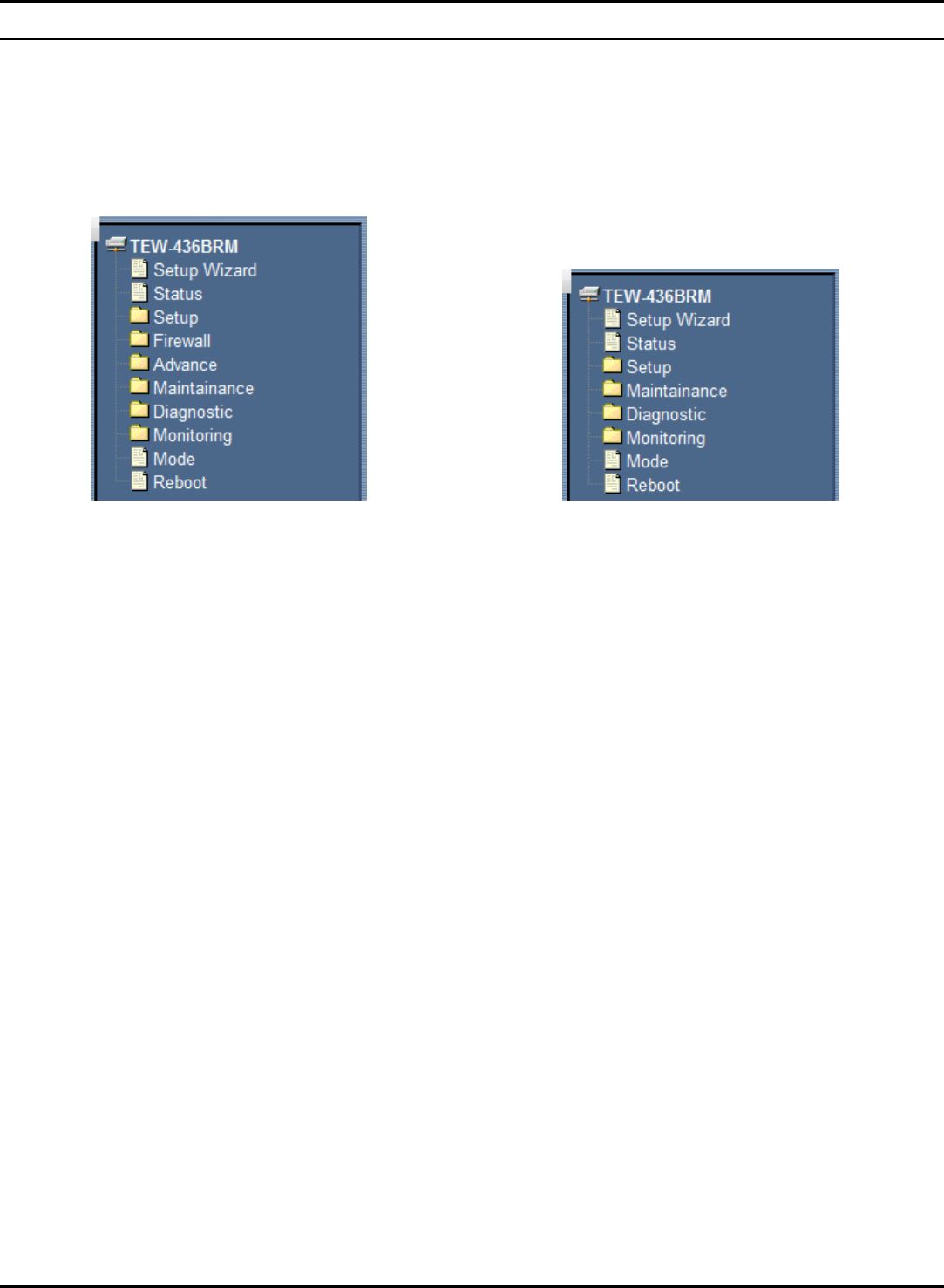
Configuration Menu
When the main page appears, find the Configuration menu in the left side of the
screen. Click on the setup item that you want to configure. There are ten options:
Setup Wizard, Status, Setup, Firewall (form router mode only), Advance (form
router mode only), Maintenance, Diagnostic, Monitoring, Mode and Reboot as
shown in the Configuration Menu screen.
Configure menu on Router mode Configure menu on Modem mode
15
SETUP WIZARD
Setup wizard is provided as part of the web configuration utility. User can simply
follow the step-by-step process to get the WLAN ADSL Router configuration ready
by clicking on` the “Wizard” button on the function menu. The following screen
will appear.
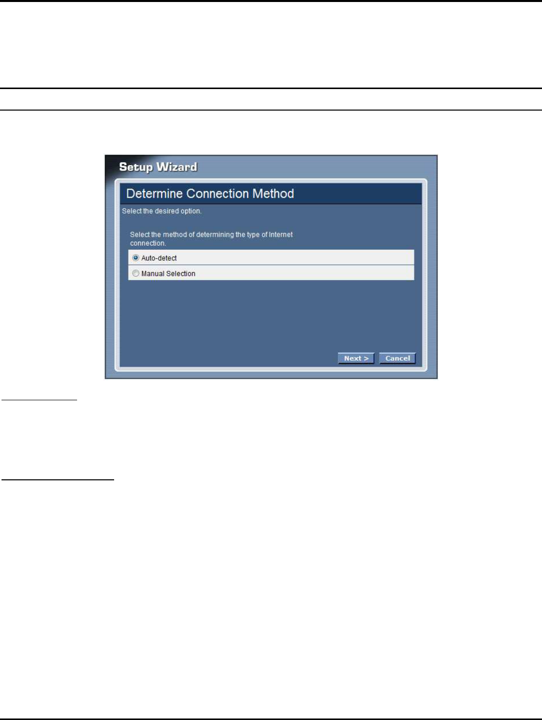
Step 1: Determine Connection Method
Choose “Auto-detect” for auto detect the Internet connection method or “Manual
Selection” for manually configure the ADSL setting.
Auto-detect
Selected the “Auto-detect” then click “Next” button, the wizard will automatically
detect the first usable PVC and automatically detect PPPoE, PPPoA, and Bridge
Protocol (with DHCP Server available)
Manual Selection
Selected the “Manual Selection” then click “Next” button, the wizard will setting
the Internet connection manually.
16
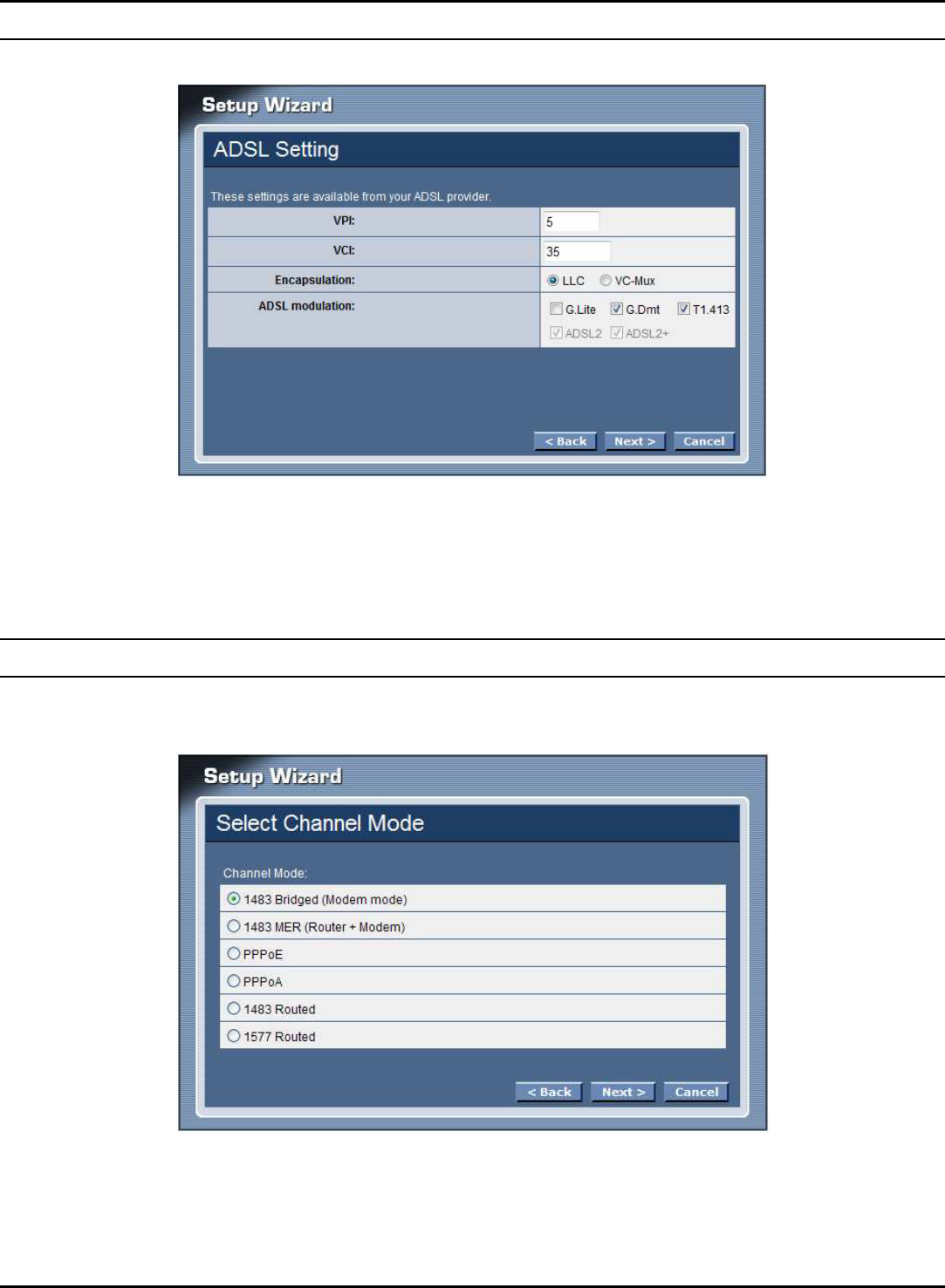
Step 2: ADSL Setting
VPI: Enter the VPI value provided by ISP
VCI: Enter the VCI value provided by ISP
Encapsulation: Select the encapsulation type for LLC or VC-Mux
ADSL modulation: Select the ADSL modulation type defined by your ISP
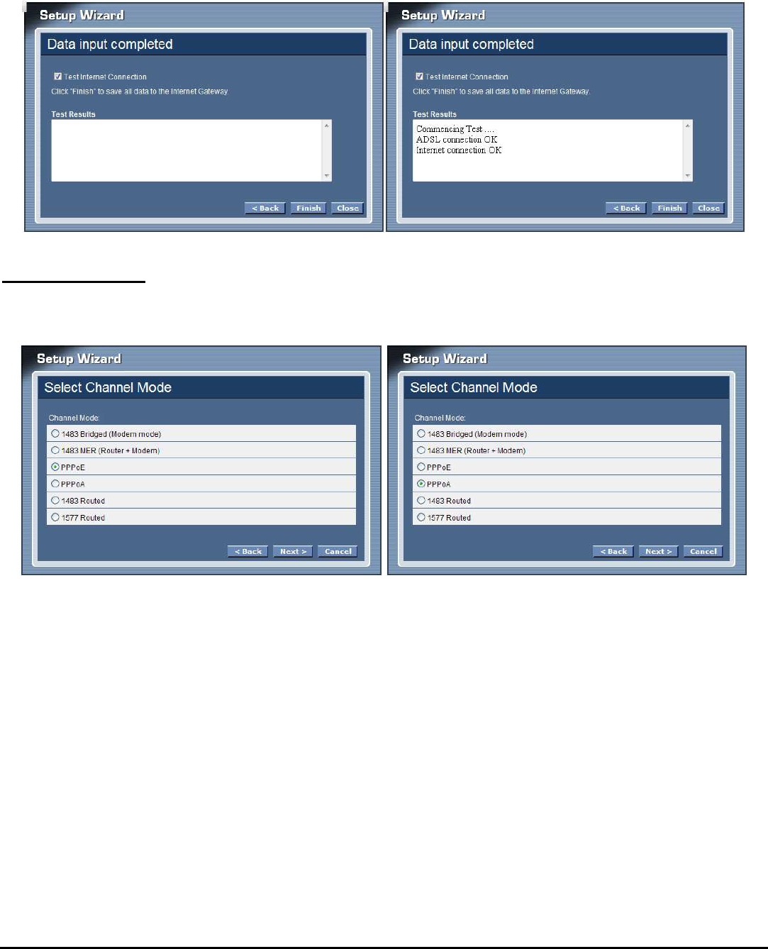
Step 3: Select Channel Mode
Select the type of network protocol for 1483 Bridged, 1483 MER, PPPoE, PPPoA
or 1483 Routed.
17
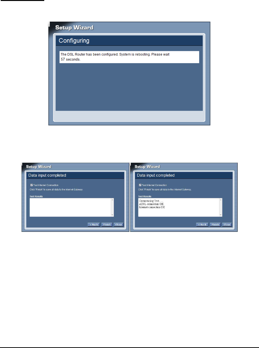
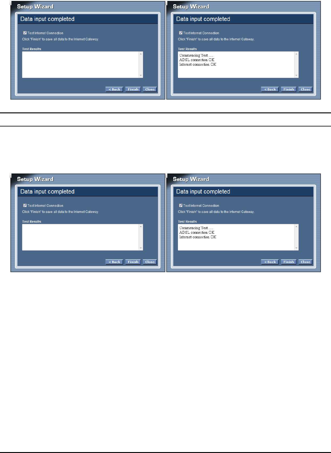
1483 Bridged
Selected the 1483 Bridged mode then click next button, the WLAN ADSL Router
will save configuration and reboot the WLAN ADSL Router.
When rebooted the WLAN ADSL Router, enabled the “Test Internet Connection”
then click finish button for test Internet connection; click close button close the
setup wizard.
18
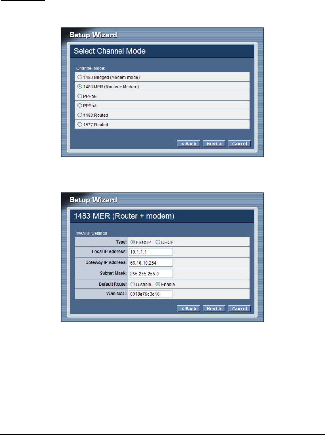
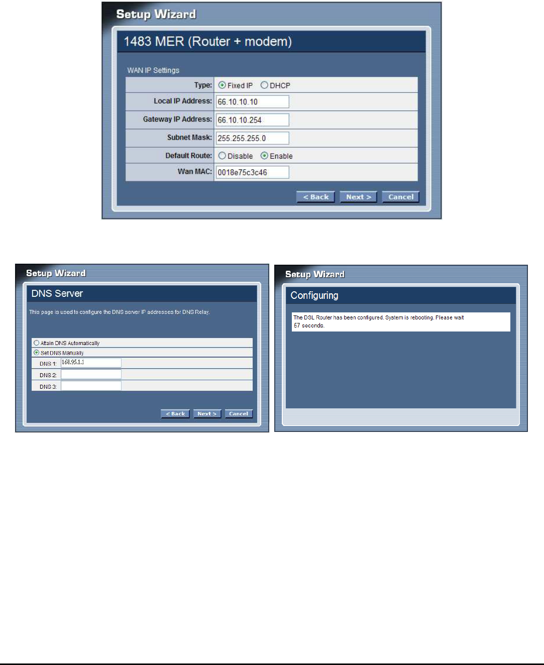
1483 MER
Selected the 1483 MER mode then click next button, continuing the WAN IP
setting.
Select whether user wants to specify an IP address manually, or want DHCP to
obtain an IP address automatically.

19
If selected to 1483 MER mode with DHCP, the follows step will going on:
Click next button to save configuration and reboot the WLAN ADSL Router
When rebooted the WLAN ADSL Router, enabled the “Test Internet Connection”
then click finish button for test Internet connection; click close button close the
setup wizard.
20
If selected to 1483 MER mode with Fixed IP, the follows step will going on:
Enter the Local IP Address, Gateway IP Address, Subnet Mask and Wan MAC (if
need to specify the other Wan MAC address) in the text boxes, click next button to
continue the DNS server setting.
Setting the DNS server assigned by DHCP or manually, click next button to save
configuration and reboot the WLAN ADSL Router
21
When rebooted the WLAN ADSL Router, enabled the “Test Internet Connection”
then click finish button for test Internet connection; click close button close the
setup wizard.
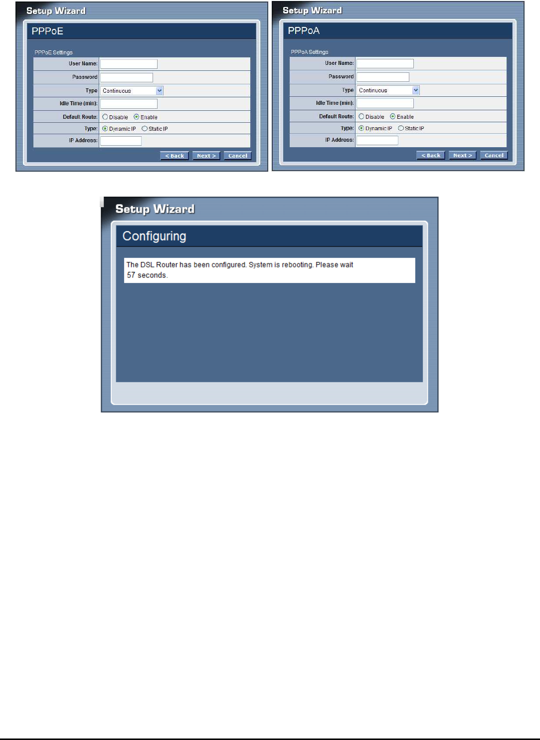
PPPoE/PPPoA
Selected the PPPoE or PPPoA mode then click next button, continue the account
setting.
User Name: Enter the username provided by ISP.
Password: Enter the password provided by ISP
Type: Select the connection type for Continuous Connecting, Connect on Demand
or Manual connecting.
Idle Time: Enter the idle time for Connect on Daemon, when no Internet access
during the idle time, the ADSL connection will auto disconnect.
Default Route: Setting the default router function disable or enable.
Type: Select the IP address assign by DHCP or manually setting.
IP Address: Enter the IP address provided by your ISP when the Type is selected
by Static IP.
22
Click next button to save configuration and reboot the WLAN ADSL Router
23
When rebooted the WLAN ADSL Router, enabled the “Test Internet Connection”
then click finish button for test Internet connection; click close button close the
setup wizard.
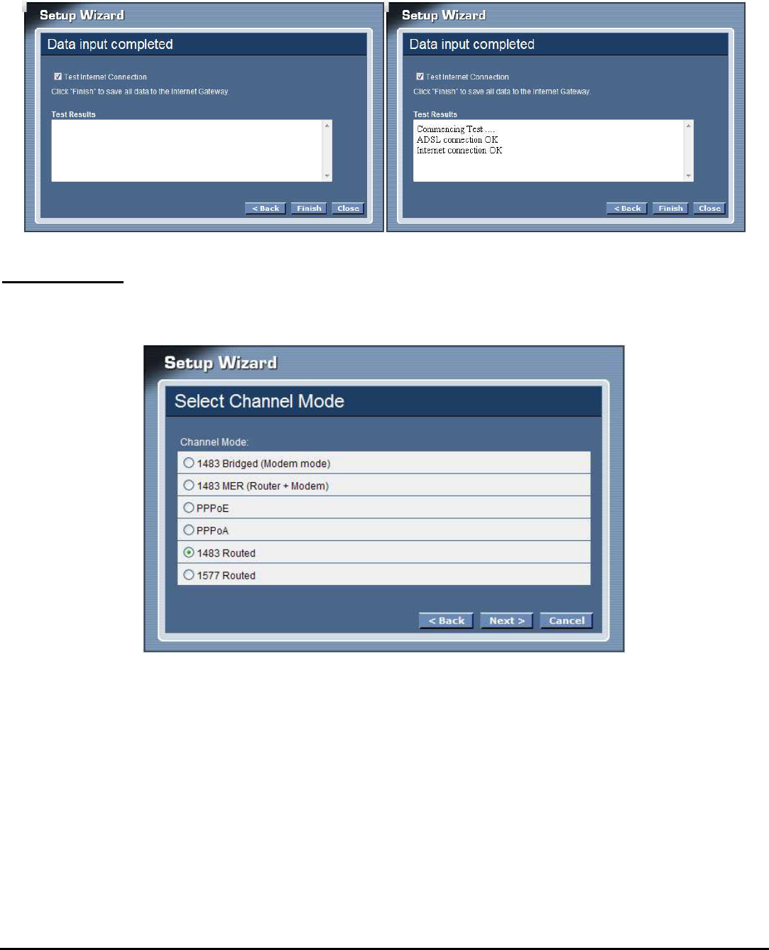
1483 Routed
Selected the 1483 Routed mode then click next button, continuing the WAN IP
setting.
NAPT: Checked to enable the NAPT on the WLAN ADSL Router.
Local IP Address : Enter local IP address provided by ISP
Gateway IP Address : Enter gateway IP address provided by ISP
Unnumbered: Checked to enable the IP unnumbered on the WLAN ADSL Router.
Default Route: Setting the default router function disable or enable.
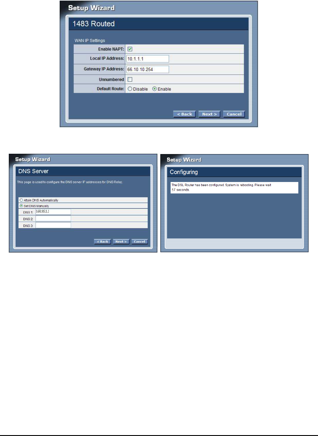
24
Setting the DNS server assigned by DHCP or manually, click next button to save
configuration and reboot the WLAN ADSL Router.
25
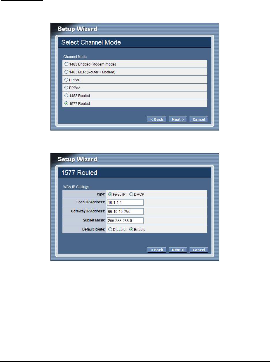
1577 Routed
Selected the 1577 Routed mode then click next button, continuing the WAN IP
setting.
Select whether user wants to specify an IP address manually, or want DHCP to
obtain an IP address automatically.
26
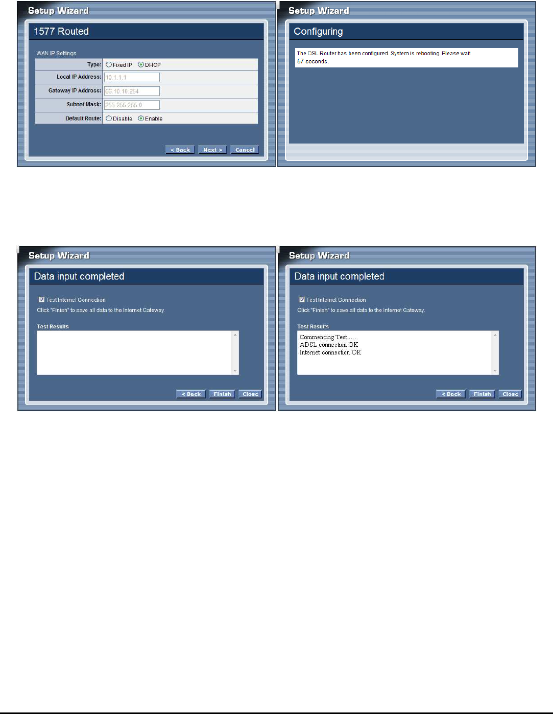
If selected to 1577 Routed mode with DHCP, the follows step will going on:
Click next button to save configuration and reboot the WLAN ADSL Router
When rebooted the WLAN ADSL Router, enabled the “Test Internet Connection”
then click finish button for test Internet connection; click close button close the
setup wizard.
27
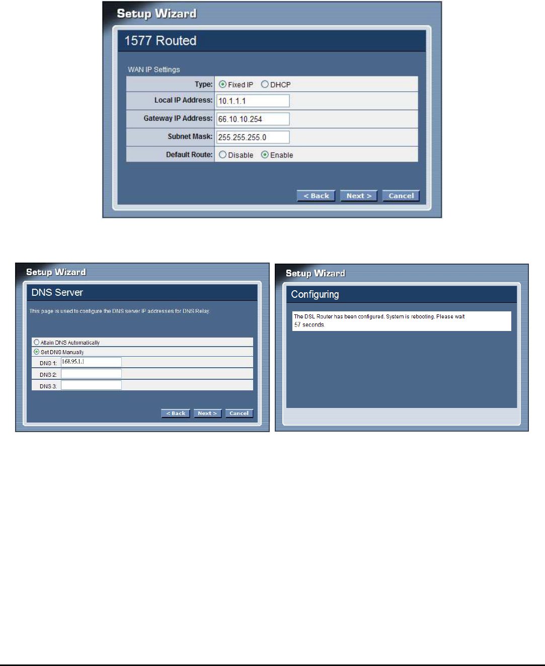
If selected to 1577 Routed mode with Fixed IP, the follows step will going on:
Enter the Local IP Address, Gateway IP Address, Subnet Mask and Wan MAC (if
need to specify the other Wan MAC address) in the text boxes, click next button to
continue the DNS server setting.
Setting the DNS server assigned by DHCP or manually, click next button to save
configuration and reboot the WLAN ADSL Router
When rebooted the WLAN ADSL Router, enabled the “Test Internet Connection”
then click finish button for test Internet connection; click close button close the
setup wizard.
28
Step 4: Completed the Setup Wizard
When rebooted the WLAN ADSL Router, enabled the “Test Internet Connection”
then click finish button for test Internet connection; click close button close the
setup wizard.
29
MANUAL SETINGS
Find that there are ten items, including Setup Wizard, Status, Setup, Firewall (form
router mode only), Advance (form router mode only), Maintenance, Diagnostic,
Monitoring, Mode and Reboot in Setup menu.
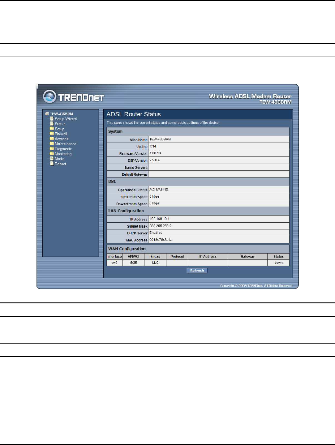
Status
This page displays the WLAN ADSL Router current status and settings. Click the
“Refresh” button to update the status.
Setup
The section enables users to configure the Internet (ADSL), LAN, Wireless, DHCP
and Time Zone setting.
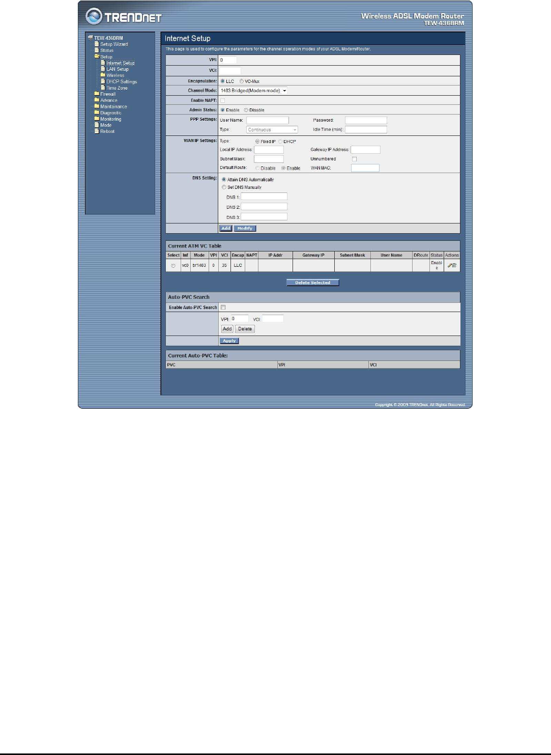
Internet Setup
The WLAN ADSL Router comes with 8 ATM Permanent Virtual Channels (PVCs)
at the most. There are mainly three operations for each of the PVC channels: add,
delete and modify. And there are several channel modes to be selected for each
PVC channel. For each of the channel modes, the setting is quite different
accordingly.
30
VPI: Virtual Path Identifier. Enter the VPI value provided by ISP.
VCI: Virtual Channel Identifier. Ethernet the VCI value provided by ISP.
Encapsulation: Select the encapsulation type LLC or VC-Mux produced by your
ISP.
Channel Mode: Select the channel mode for 1483 Bridged, 1483 MER, PPPoE,
PPPoA, 1483 Routed or 1577 Routed provide by ISP.
Enable NAPT: Checked to enable the NAPT function on the WLAN ADSL Router.
Admin Status: Enable or disable the ATM VC setting when adding to the ATM
VC Table.
PPP Settings: When the channel mode selected by PPPoE or PPPoA.
User Name: Enter the user name provide by ISP.
Password: Enter the user name provide by ISP.
Type: Select the connection type for “Continuous”, “Connect on Daemon” or
“Manual” connect.

31
Idle Time: Enter the idle time for Connect on Daemon, when no Internet access
during the idle time, the ADSL connection will auto disconnect.
WAN IP Settings:
Type: Select whether user wants to specify an IP address manually, or want
DHCP to obtain an IP address automatically. When Fixed IP is selected, type the
Local IP Address, Gateway IP Address and Subnet Mask in the text boxes. User’s
ISP will provide with this information.
Unnumbered: Checked to enable the IP unnumbered on the WLAN ADSL
Router.
Default Route: Setting the default router function disable or enable.
WAN MAC: Enter the specified WAN MAC address provided by your ISP
DNS Setting:
Attain DNS Automatically: Select this item if you want to use the DNS servers
obtained by the WAN interface via the auto-configuration mechanism.
Set DNS Manually: Select this item to configure up to three DNS IP addresses.
DNS 1~3: Ethernet the IP address of the DNS server.
Add Button: Click add button to add the new VC setting to the ATM VC Table.
Modify Button: Selected on of VC setting from the Current ATM VC Table then
click the Modify button to save the modified VC setting.
Current ATM VC Table: Shows all of the ATM VC settings in the table.
Auto-PVC Search: Enable the Auto-PVC Search or add new PVC setting
manually.
Current Auto-PVC Table: Shows all of the Auto-PVC settings in the table.
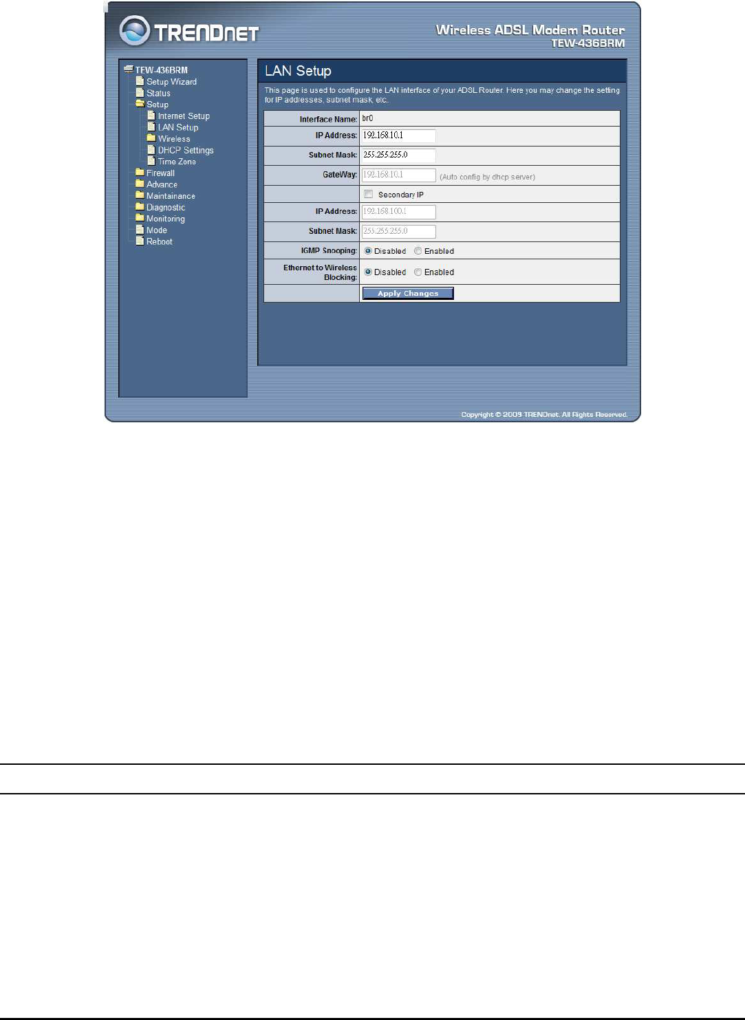
LAN Setup
This screen enables users to set up the WLAN ADSL Router WAN connection,
specify the IP address for the WAN, add DNS numbers, and enter the MAC address.
32
IP Address: This is the IP address of the router. The default IP address is
192.168.10.1.
Subnet Mask: Type the subnet mask for the router in the text box. The default
subnet mask is 255.255.255.0.
Secondary IP: Checked to enable the secondary IP address setting on the LAN.
IP Address: The secondary IP address setting of the LAN.
Subnet Mask: The secondary Subnet Mask setting of the LAN.
IGMP Snooping: Enable/disable the IGMP snooping function for the multiple
bridged LAN ports.
Ethernet to Wireless Blocking: When enabled the Ethernet to Wireless Blocking,
all of Ethernet users can’t communicate with WLAN users.
Wireless
This section enables users to configuration the wireless communications parameters
for the WLAN ADSL Router.
33
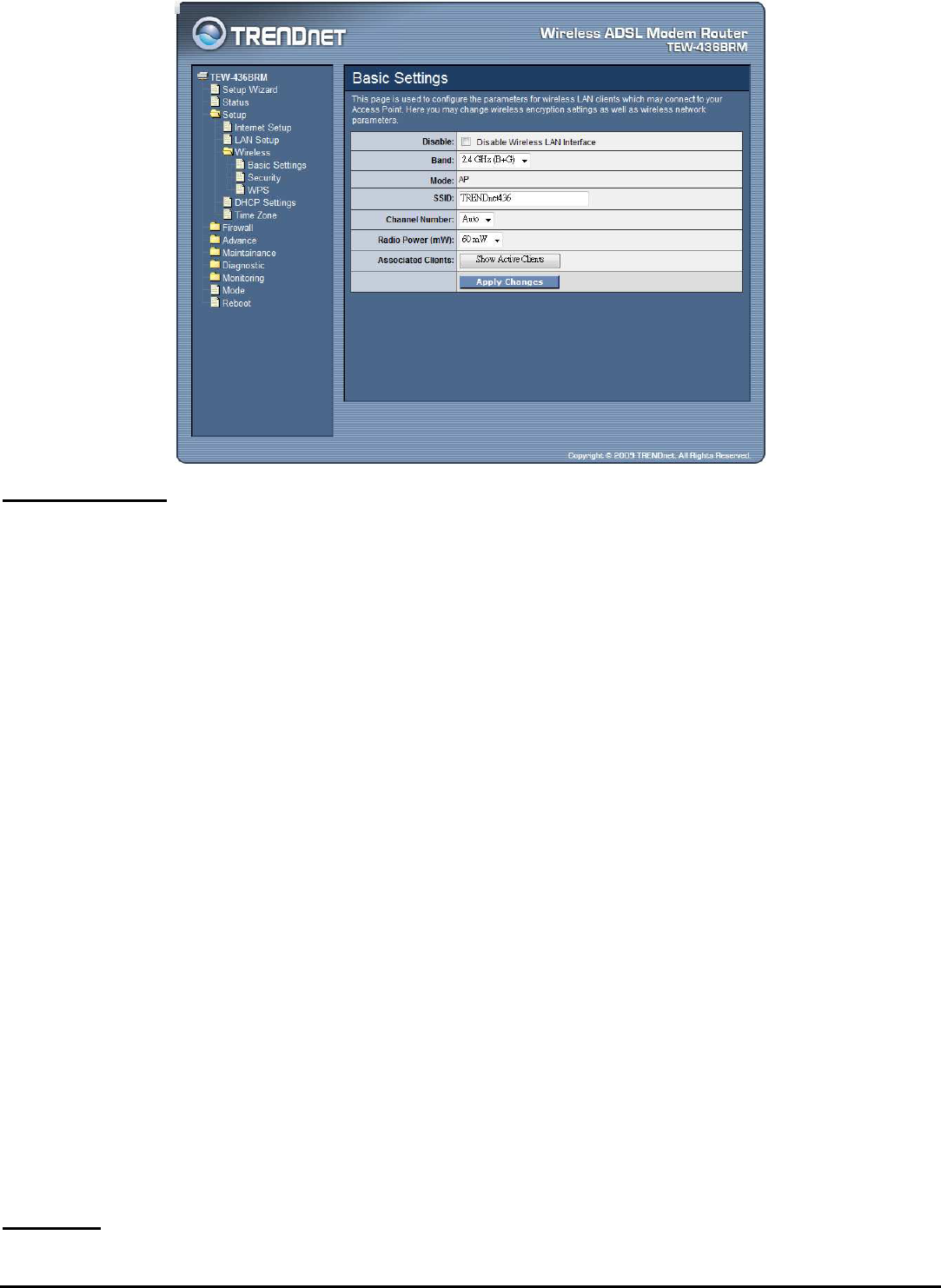
Basic Settings
This page allow user to enable and disable the wireless LAN function, create a
SSID, and select the channel for wireless communications.
Disable: Checked to disable the wireless function of the WLAN ADSL Router.
Band: Select one of the following:
2.4Ghz (B+G) - Selected if you are allowing both 802.11b and 802.11g
wireless clients connect to the WLAN ADSL Router at the same time.
2.4Ghz (B) - Selected if you are allowing the 802.11b wireless clients connect
to the WLAN ADSL Router only.
2.4Ghz (G) - Selected if you are allowing the 802.11g wireless clients
connect to the WLAN ADSL Router only.
SSID: Type an SSID in the text box. The SSID of any wireless device must match
the SSID typed here in order for the wireless device to access the LAN and WAN
via the WLAN ADSL Router.
Channel: Select a transmission channel for wireless communications. The channel
of any wireless device must match the channel selected here in order for the
wireless device to access the LAN and WAN via the WLAN ADSL Router.
Radio Power (mW): The maximum output power for wireless LAN: 15mW,
30mW or 60mW.
Associated Clients: Click the “Show Active Client” button displays the
information of connected wireless clients.
Security
34
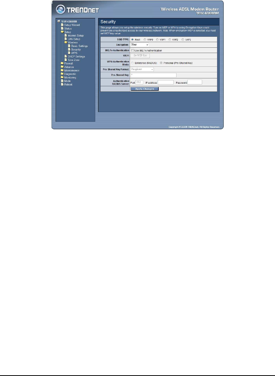
SSID TYPE: The WLAN ADSL Router supports up to four multiple SSID feature
(Multiple Virtual AP), select which AP (Root AP, VAP0~VAP3) will configure the
security setting.
Encryption: There are 4 types of security to be selected. To secure your WLAN,
it’s strongly recommended to enable this feature.
WEP: Make sure that all wireless devices on your network are using the same
encryption level and key. Click Set WEP Key button to set the encryption key.
WPA (TKIP): WPA uses Temporal Key Integrity Protocol (TKIP) for data
encryption. TKIP utilized a stronger encryption method and incorporates Message
Integrity Code (MIC) to provide protection against hackers.
WPA2 (AES): WPA2, also known as 802.11i, uses Advanced Encryption
Standard (AES) for data encryption. AES utilized a symmetric 128-bit block data
encryption.
WAP2 Mixed: The AP supports WPA (TKIP) and WPA2 (AES) for data
encryption. The actual selection of the encryption methods will depend on the
clients.
802.1x Authentication: Checked to enable the 802.1x authentication. This
option is selectable only when the “Encryption” is selected to either None or WEP.
If the “Encryption” is WEP, you need to further select the WEP key length to be
either WEP 64bits or WEP 128bits.
WEP: Click the “Set WEP Key” button to setting WEP key when the
“Encryption” is selected to “WEP”.

35
SSID TYPE: The WLAN ADSL Router supports up to four multiple SSID
feature (Multiple Virtual AP), select which AP (Root AP, VAP0~VAP3) will
setting the WEP key.
Key Length: Select the level of encryption from the drop-down list 64 and 128-
bit encryption.
Key Format: Select the key format from the drop-down list HEX or ASCII.
Default TX Key: Select which encryption key 1~4 will be use to default TX
key.
Encryption Key 1 ~ 4: Enables users to create up to 4 different WEP keys,
manually enter a set of values for each key.
WPA Authentication Mode: There are 2 types of authentication mode for
WPA.
Enterprise (RADIUS): WPA RADIUS uses an external RADIUS server to
perform user authentication. To use WPA RADIUS, enter the IP address of the
RADIUS server, the RADIUS port (default is 1812) and the shared secret from
the RADIUS server. Please refer to “Authentication RADIUS Server” setting
below for RADIUS setting.
Personal (Pre-Shared Key): Pre-Shared Key authentication is based on a
shared secret that is known only by the parties involved. To use WPA Pre-
Shared Key, select key format and enter a password in the “Pre-Shared Key
Format” and “Pre-Shared Key” setting respectively. Please refer to “Pre-
Shared Key Format” and “Pre-Shared Key” setting below.
Pre-Shared Key Format:
Passphrase: Select this to enter the Pre-Shared Key secret as user-friendly
textual secret.
Hex (64 characters): Select this to enter the Pre-Shared Key secret as
hexadecimal secret.

36
Pre-Shared Key: Specify the shared secret used by this Pre-Shared Key. If the
“Pre-Shared Key Format” is specified as Passphrase, then it indicates a passphrase
of 8 to 63 bytes long; or if the “Pre-Shared Key Format” is specified as
Passphrase, then it indicates a 64-hexadecimal number.
Authentication RADIUS Server: If the WPA-RADIUS is selected at “WPA
Authentication Mode”, the port (default is 1812), IP address and password of
external RADIUS server are specified here.
WPS
Although home Wi-Fi networks have become more and more popular, users still
have trouble with the initial set up of network. This obstacle forces users to use the
open security and increases the risk of eavesdropping. Therefore, The Wi-Fi
Protected Setup (WPS) is designed to ease set up of security-enabled Wi-Fi
networks and subsequently network management. The largest difference between
WPS-enabled devices and legacy devices is that users do not need the knowledge
about SSID, channel and security settings, but they could still surf in a security-
enabled Wi-Fi network. This device supports Push Button method and PIN method
for WPS. The following sub-paragraphs will describe the function of each item.
The webpage is as below. Although home Wi-Fi networks have become more and
more popular, users still have trouble with the initial set up of network. This
obstacle forces users to use the open security and increases the risk of
eavesdropping. Therefore, The Wi-Fi Protected Setup (WPS) is designed to ease set
up of security-enabled Wi-Fi networks and subsequently network management. The
largest difference between WPS-enabled devices and legacy devices is that users do
not need the knowledge about SSID, channel and security settings, but they could
still surf in a security-enabled Wi-Fi network. This device supports Push Button
method and PIN method for WPS. The following sub-paragraphs will describe the
function of each item. The webpage is as below.
37
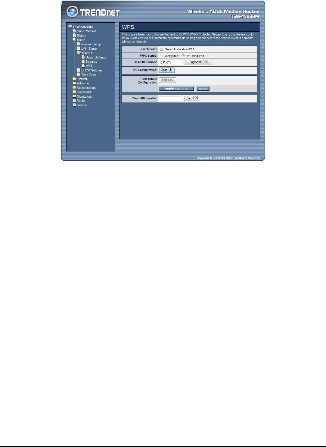
Disable WPS: Checked to disable the Wi-Fi protected Setup.
WPS Status: When the WLAN ADSL Router settings are factory default (out of
box), it is set to open security and un-configured state. “WPS Status” will display
it as “UnConfigured”. If it already shows “Configured”, some registrars such as
Vista WCN will not configure AP. Users will need to go to the “Backup/Restore”
page and click “Reset” to reload factory default settings.
Self-PIN Number: The “Self-PIN Number” is AP’s PIN. Whenever users want
to change AP’s PIN, they could click “Regenerate PIN” and then click “Apply
Changes”. Moreover, if users want to make their own PIN, they could enter four-
digit PIN without checksum and then click “Apply Changes”. However, this
would not be recommended since the registrar side needs to be supported with
four-digit PIN.
PIN Configuration: Click the “Start PIN” button to start the PIN method of
WPS.
Push Button Configuration: Click the “Start PBC” button to start the push btton
method of WPS.
Client PIN Number: It is only used when users want their station to join AP’s
network. The length of PIN is limited to four or eight numeric digits. If users enter
eight-digit PIN with checksum error, there will be a warning message popping up.
If users insist on this PIN, AP will take it.
38
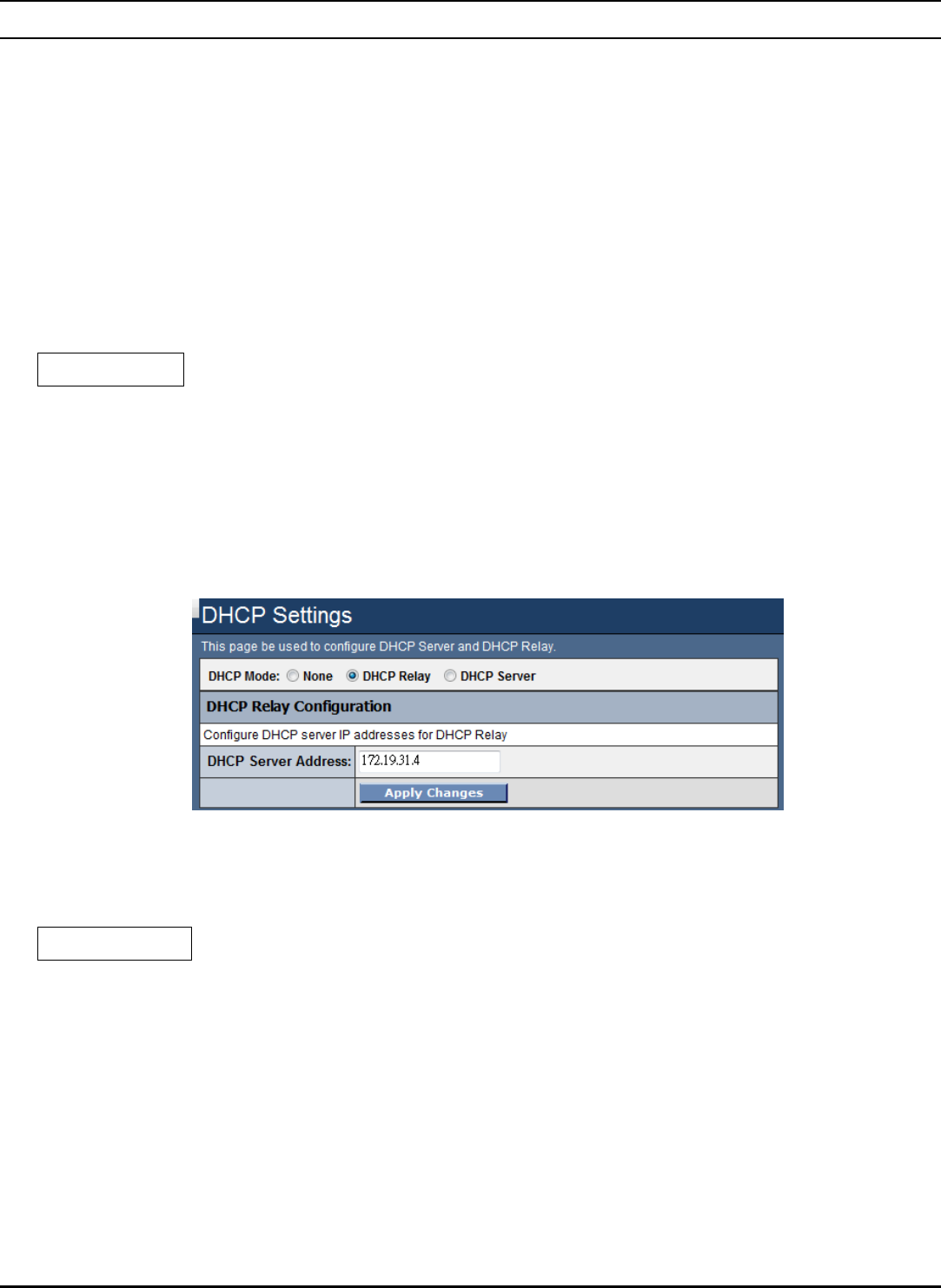
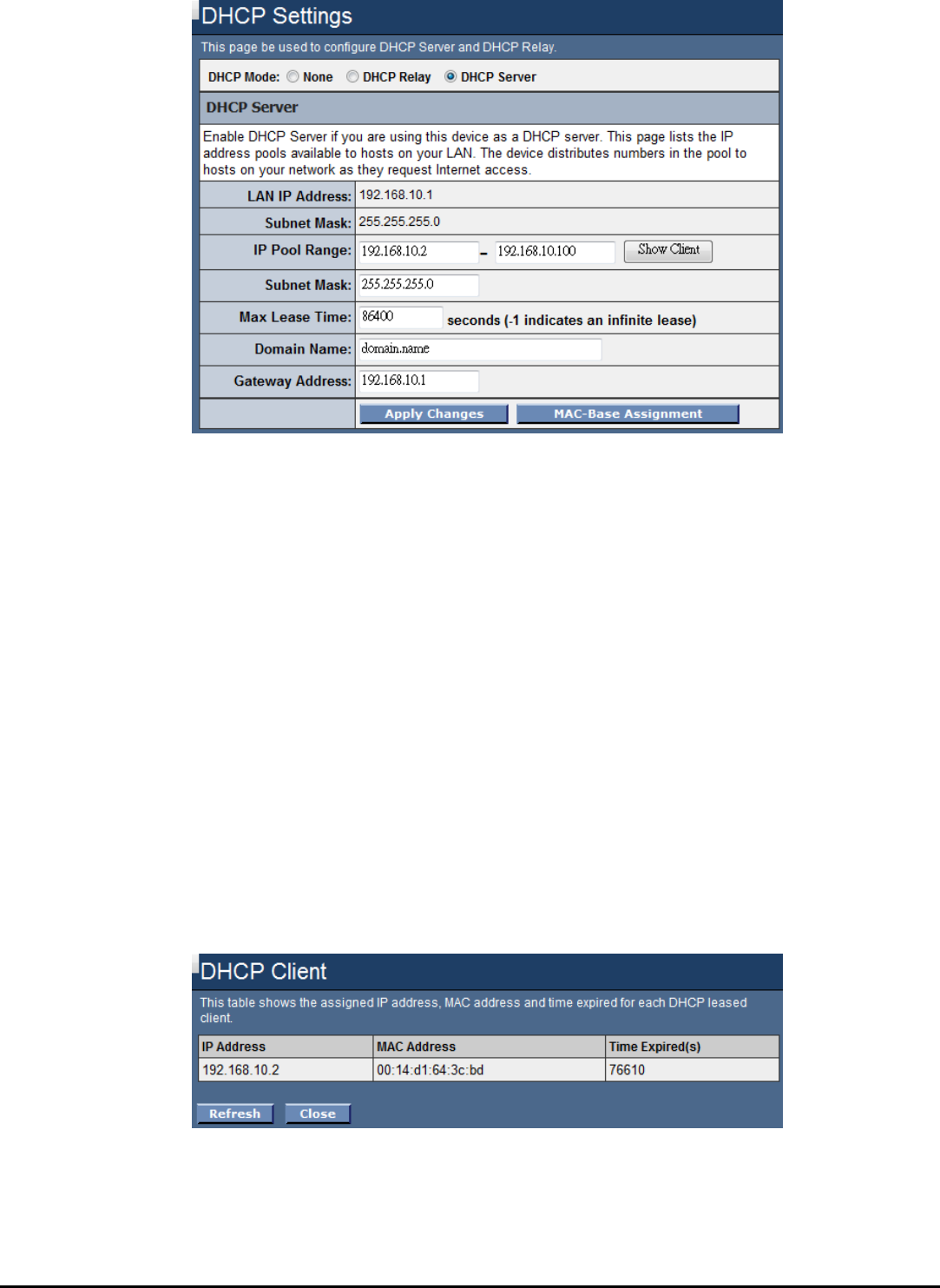
DHCP Settings
You can configure your WLAN ADSL Router to use the Dynamic Host
Configuration Protocol (DHCP). This section provides DHCP instructions for
implementing it on your network by selecting the role of DHCP protocol that this
device wants to play.
DHCP Mode: There are two different DHCP roles that this device can act as:
DHCP Server and DHCP Relay. When acting as DHCP server, you can setup the
server parameters at the below DHCP Server setting; while acting as DHCP Relay,
you can setup the relay at the below DHCP Relay setting. Otherwise, selected the
None to disable the DHCP service.
DHCP Relay
Some ISPs perform the DHCP server function for their customers’ home/small
office network. In this case, you can configure this device to act as a DHCP
relay agent. When a host on your network requests Internet access, the device
contacts your ISP to obtain the IP configuration, and then forward that
information to the host. You should set the DHCP mode after you configure the
DHCP relay.
DHCP Server Address: Specify the IP address of your ISP’s DHCP server.
Requests for IP information from your LAN will be passed to the default
gateway, which should route the request appropriately.
DHCP Server
By default, the device is configured as a DHCP server, with a predefined IP
address pool of 192.168.10.2 through 192.168.10.100 (subnet mask
255.255.255.0).
39
IP Pool Range: Specify the lowest and highest addresses in the pool.
Subnet Mask: Specify the subnet mask value.
Max Lease Time: The Lease Time is the amount of time that a network user is
allowed to maintain a network connection to the device using the current
dynamic IP address. At the end of the Lease Time, the lease is either renewed or
a new IP is issued by the DHCP server. The amount of time is in units of
seconds. The default value is 86400 seconds (1 day). The value –1 stands for the
infinite lease.
Domain Name: A user-friendly name that refers to the group of hosts (subnet)
that will be assigned addresses from this pool.
Gateway Address: Specify the gateway IP address.
Show Client: When click the “Show Client” button, all dynamic DHCP client
computers are listed in the new window and providing the IP address, MAC
address and Time Expired of the client.
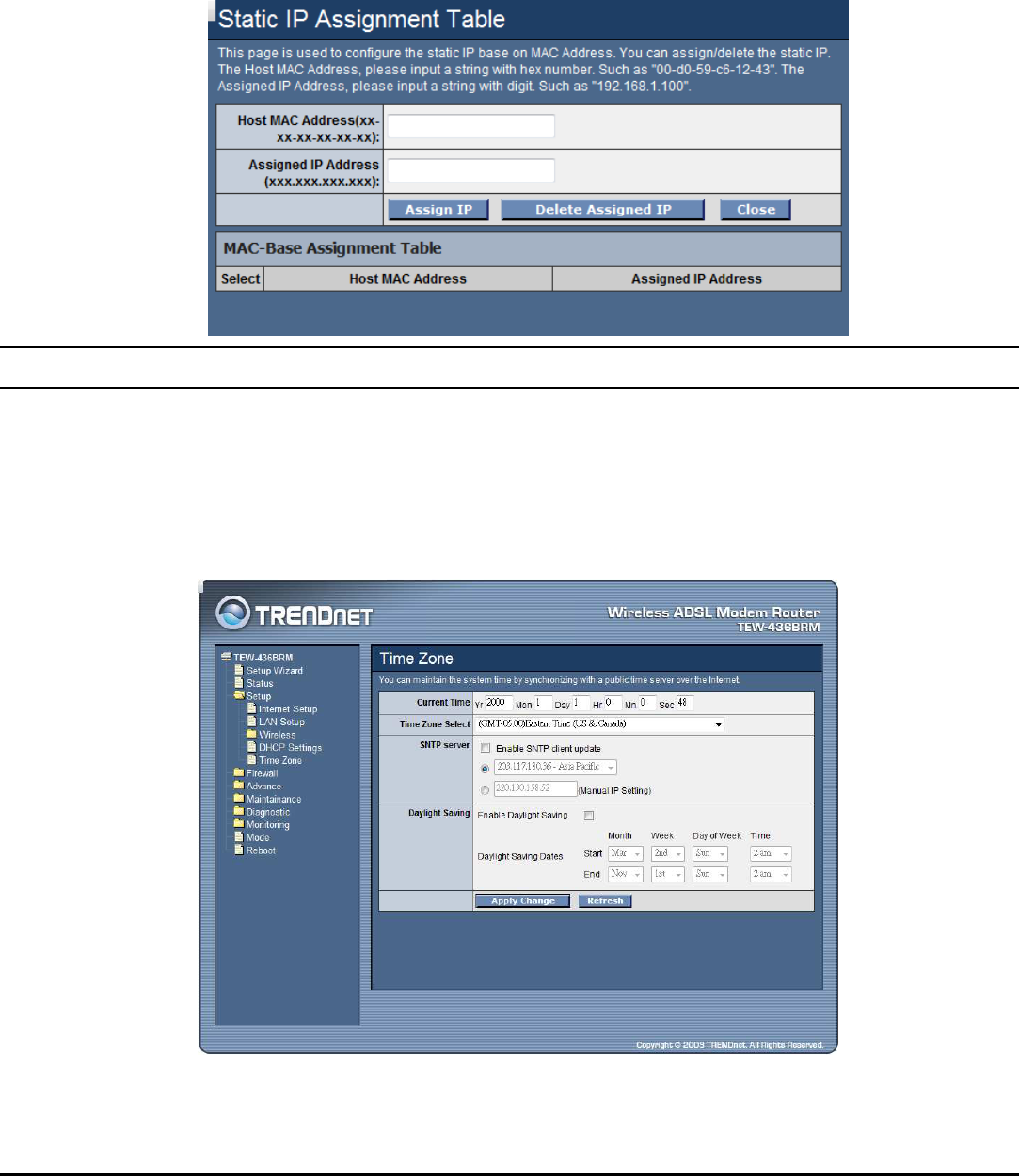
40
MAC-Base Assignment: Click the “MAC-Base Assignment” button to
configure the static IP base on MAC Address. You can assign/delete the static IP.
The Host MAC Address, please input a string with hex number. Such as "00-d0-
59-c6-12-43". The Assigned IP Address, please input a string with digit. Such as
"192.168.10.100". Click “Assign IP” button to add the static DHCP setting to
the MAC-Base Assignment Table.
Time Zone
Simple Network Timing Protocol (SNTP) is a protocol used to synchronize the
system time to the public SNTP servers. The WLAN ADSL Router supports SNTP
client functionality in compliance with IETF RFC2030. SNTP client functioning in
daemon mode which issues sending client requests to the configured SNTP server
addresses periodically can configure the system clock in the WLAN ADSL Router.
Current Time: The current time of the specified time zone. You can set the
current time by yourself or configured by SNTP.
41
Time Zone Select: The time zone in which the WLAN ADSL Router resides.
Enable SNTP client update: Enable the SNTP client to update the system clock.
SNTP server: The IP address or the host name of the SNTP server. You can
select from the list or set it manually.
Daylight Saving: Checked to enable daylight saving time. When enabled, select
the start and end date for daylight saving time.
Firewall – Used only on Router mode settings
The Firewall setting is for the WLAN ADSL Router is configured on Router mode
only. Please refer the Mode setting in page 79.
Firewall contains several features that are used to deny or allow traffic from passing
through the device.
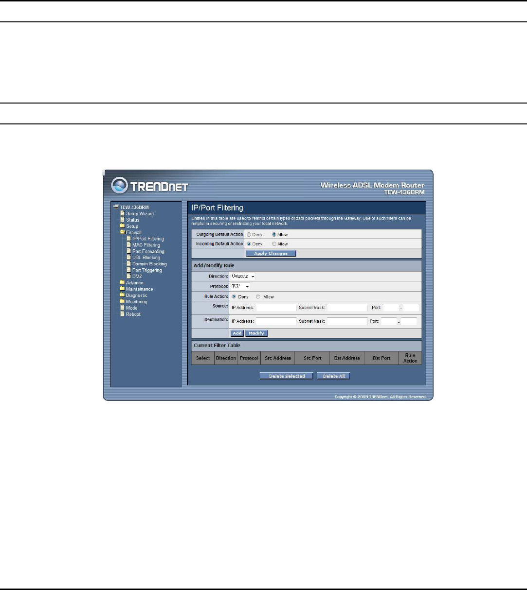
IP/Port Filtering
The IP/Port filtering feature allows you to deny/allow specific services or
applications in the forwarding path.
Outgoing Default Action: Specify the default action on the LAN to WAN
forwarding path.
Incoming Default Action: Specify the default action on the WAN to LAN
forwarding path.
42
Add/Modify Rule
Add or modify the IP/Port filtering rule.
Direction: Select the traffic forwarding direction “Outgoing” or “Incoming”.
Protocol: Select the protocol type for TCP, UDP or ICMP.
Rule Action: Deny or allow traffic when matching this rule.
Source: The source IP address, Subnet Mask and Port range assigned to the traffic
on which filtering is applied.
Destination: The destination IP address, Subnet Mask and Port range assigned to
the traffic on which filtering is applied.
Add: Click the “Add” button to save the rule entry to the configuration.
Modify: Click the “Modify” button to modify the selected rule form the Current
Filter Table.
Delete Selected: Click the “Delete Selected” button to delete the selected rule from
Current Filter Table.
Delete All: Click the “Delete All” button to delete the all of rule in the Current
Filter Table.
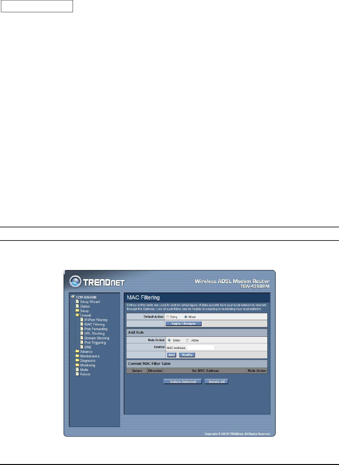
MAC Filtering
The MAC filtering feature allows you to define rules to allow or deny frames
through the device based on source MAC address, and traffic direction.
Default Action: Specify the default action on the LAN to WAN forwarding path.
43
Add/Modify Rule
Add or modify the MAC filtering rule.
Rule Action: Deny or allow traffic when matching this rule.
Source: The source MAC address. It must be xxxxxxxxxxxx format. Blanks can be
used in the MAC address space and are considered as don’t care.
Add: Click the “Add” button to save the rule entry to the configuration.
Modify: Click the “Modify” button to modify the selected rule form the Current
MAC Filter Table.
Delete Selected: Click the “Delete Selected” button to delete the selected rule from
Current MAC Filter Table.
Delete All: Click the “Delete All” button to delete the all of rule in the Current
MAC Filter Table.
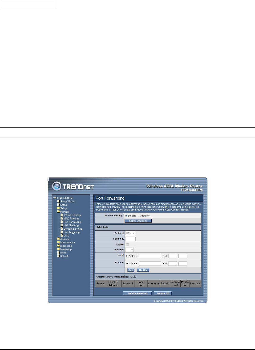
Port Forwarding
Firewall keeps unwanted traffic from the Internet away from your LAN computers.
Add a Port Forwarding entry will create a tunnel through your firewall so that the
computers on the Internet can communicate to one of the computers on your LAN
on a single port.
Port Forwarding: Select to enable or disable the port forwarding feature.

44
Add/Modify Rule
Add or modify the Port Forwarding rule.
Protocol: Select the protocol type for TCP, UDP or Both (TCP and UTP).
Enable: Check to enable this rule.
Interface: Select the WAN interface on which the port-forwarding rule is to be
applied.
Local: The local IP address and Port range assigned to the traffic on which filtering
is applied.
Destination: The remote IP address and Port range assigned to the traffic on which
filtering is applied.
Add: Click the “Add” button to save the rule entry to the configuration.
Modify: Click the “Modify” button to modify the selected rule form the Current
Port Forwarding Table.
Delete Selected: Click the “Delete Selected” button to delete the selected rule from
Current Port Forwarding Table.
Delete All: Click the “Delete All” button to delete the all of rule in the Current Port
Forwarding Table.
45
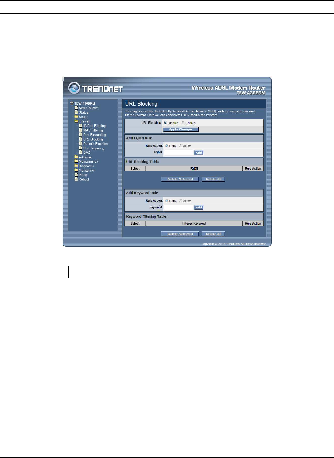
URL Blocking
The URL Blocking is the web filtering solution. The firewall includes the ability to
block access to specific web URLs based on string matches. This can allow large
numbers of URLs to be blocked by specifying only a FQDN (such as
tw.yahoo.com). The URL Blocking enforce a Web usage policy to control content
downloaded from, and uploaded to, the Web.
URL Blocking: Select to enable or disable the URL blocking feature.
Add FQDN Rule
Rule Action: Deny or allow traffic when matching this rule.
FQDN: A fully qualified domain name (or FQDN) is an unambiguous domain
name that specifies the node's position in the DNS tree hierarchy absolutely, such
as tw.yahoo.com. The FQDN will be blocked to access.
Add: Click the “Add” button to save the rule entry to the configuration.
Delete Selected: Click the “Delete Selected” button to delete the selected rule from
URL Blocking Table.
Delete All: Click the “Delete All” button to delete the all of rule in the URL
Blocking Table.
46
Add Keyword Rule
Rule Action: Deny or allow traffic when matching this rule.
Keyword: The filtered keyword such as yahoo. If the URL includes this keyword,
the URL will be blocked to access.
Add: Click the “Add” button to save the rule entry to the configuration.
Delete Selected: Click the “Delete Selected” button to delete the selected rule from
Keyword Filtering Table.
Delete All: Click the “Delete All” button to delete the all of rule in the Keyword
Filtering Table.
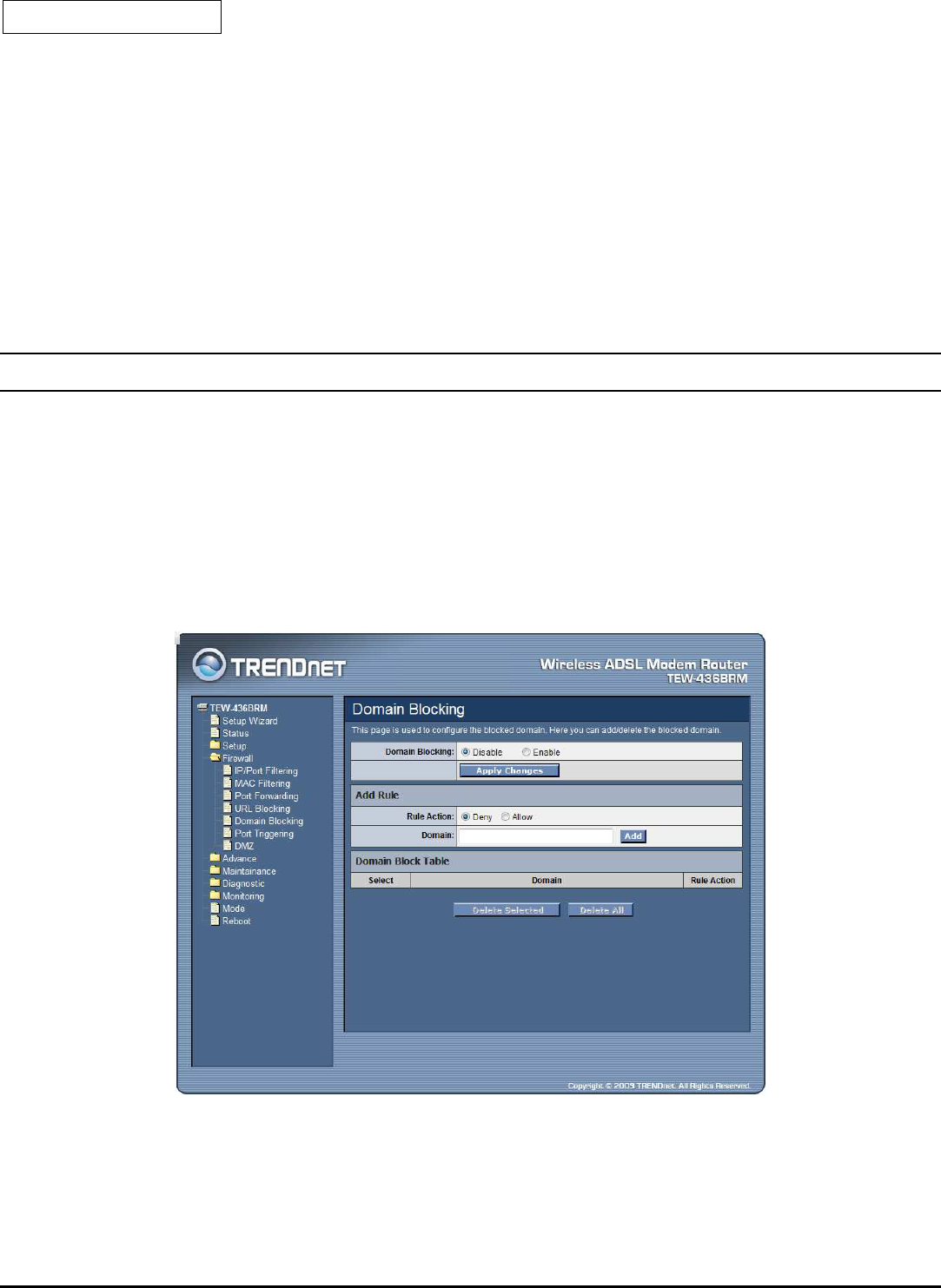
Domain Blocking
The firewall includes the ability to block access to specific domain based on string
matches. For example, if the URL of Taiwan Yahoo web site is “tw.yahoo.com”
and you enter “yahoo.com”, the firewall will block all the DNS queries with
“yahoo.com” string. So the Host will be blocked to access all the URLs belong to
“yahoo.com” domain. That means you can protect your computer, your house, your
office and anything else that uses DNS from being able to service domains that you
don’t want to load.
Domain Blocking: Select to enable or disable the Domain blocking feature.
47
Add Rule
Rule Action: Deny or allow traffic when matching this rule.
Domain: Enter the blocked domain.
Add: Click the “Add” button to save the rule entry to the configuration.
Delete Selected: Click the “Delete Selected” button to delete the selected rule from
Domain Block Table.
Delete All: Click the “Delete All” button to delete the all of rule in the Domain
Blocking Table.
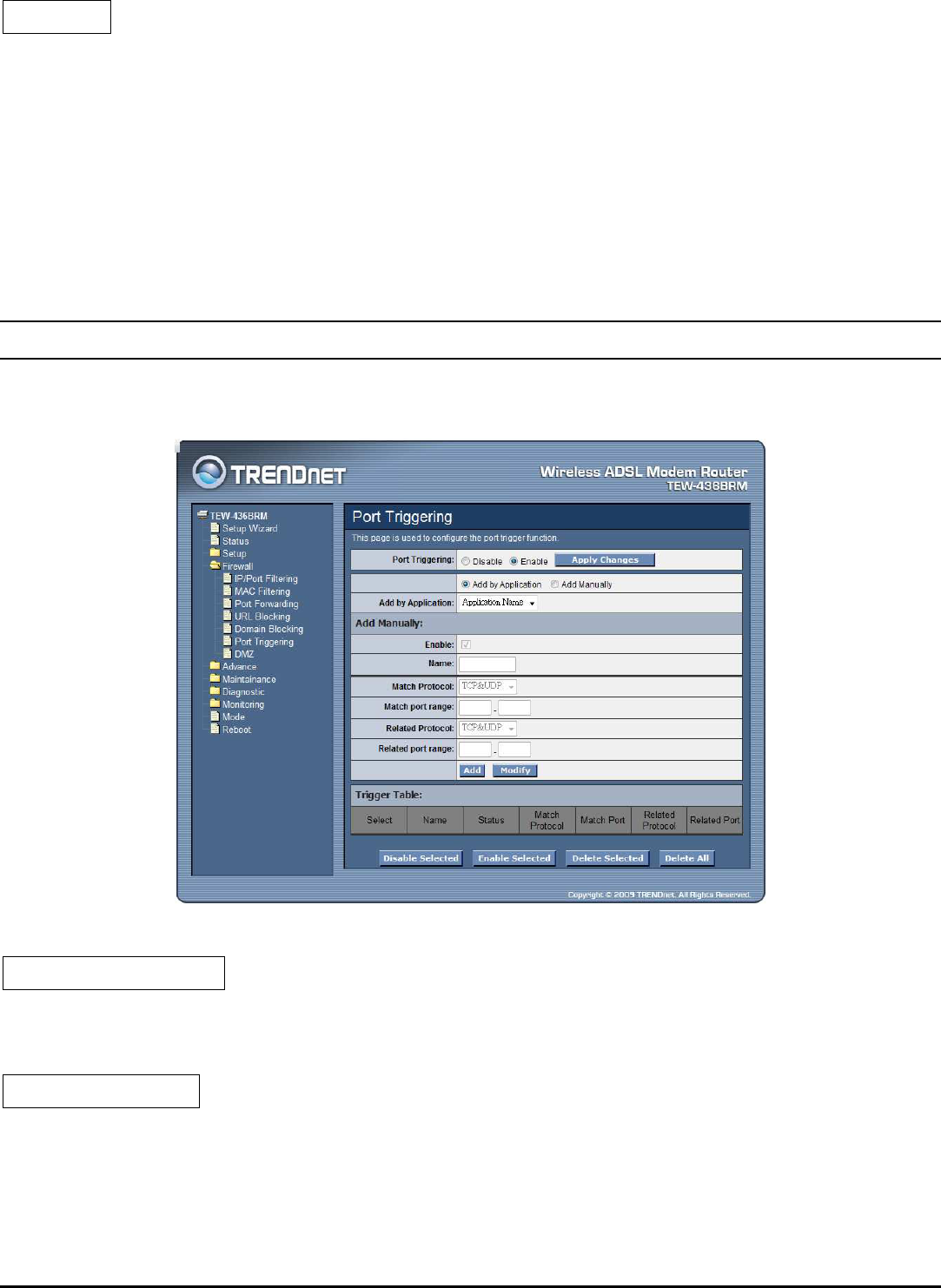
Port Triggering
The Port Triggering enables users to specify special applications, such as games
which require multiple connections that are blocked by NAT.
Port Triggering: Select to enable or disable the Port Triggering feature.
Add by Application
Add by Application: Select pre-define the application rule from list then click
“Add” button to add the selected application rule.
Add by Manually
Enable: Check to enable this rule.
Name: Enter a descriptive name for the application rule.
Match Protocol: Select the outgoing protocol type for TCP, UDP or TCP&UTP.
48
Match port range: Enter the outgoing port range that can be used to access the
application in the text boxes.
Related Protocol: Select the incoming protocol type for TCP, UDP or TCP&UTP.
Related port range: Enter the incoming port range that can be used to access the
application in the text boxes.
Add: Click the “Add” button to save the rule entry to the configuration.
Modify: Click the “Modify” button to modify the selected rule form the Trigger
Table.
Delete Selected: Click the “Delete Selected” button to delete the selected rule from
Trigger Table.
Delete All: Click the “Delete All” button to delete the all of rule in the Trigger
Table.
Disable Selected: Click the “Disable Selected” button to disable the selected rule
from Trigger Table.
Enable Selected: Click the “Enable Selected” button to Enable the selected rule
from Trigger Table.
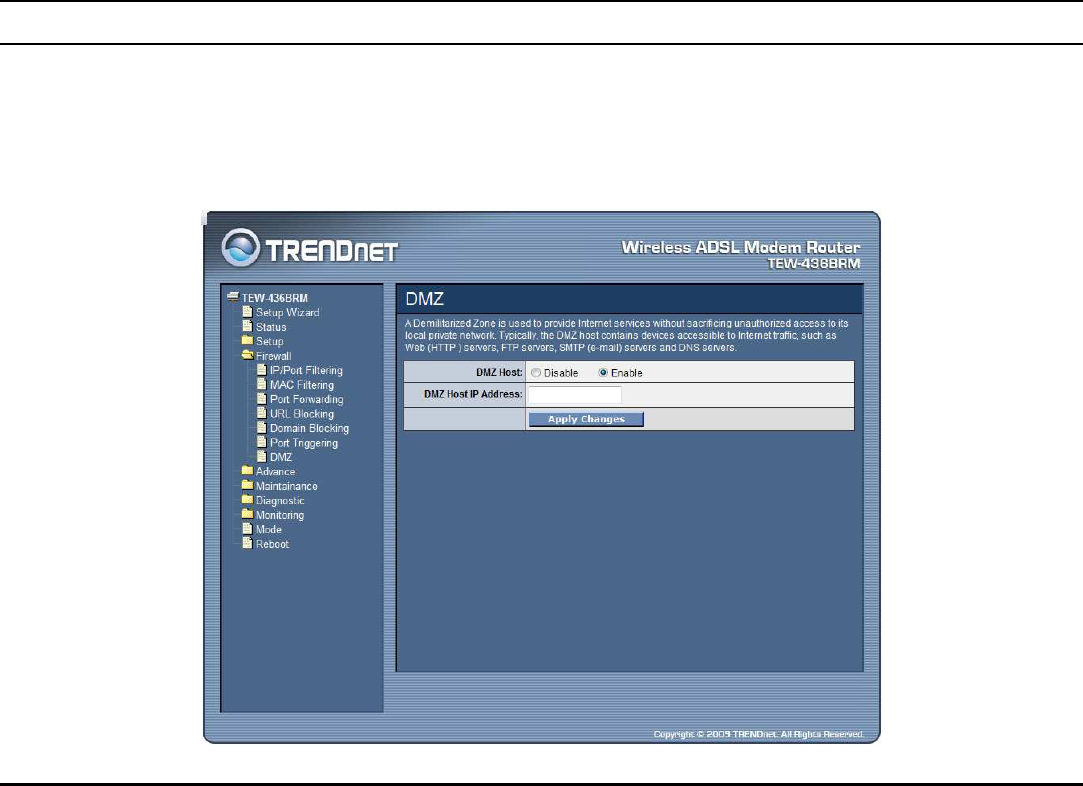
DMZ
A DMZ (Demilitarized Zone) allows a single computer on your LAN to expose
ALL of its ports to the Internet. Enter the IP address of that computer as a DMZ
(Demilitarized Zone) host with unrestricted Internet access. When doing this, the
DMZ host is no longer behind the firewall.
49
DMZ Host: Select to enable or disable the DMZ feature.
DMZ Host IP Address: Enter a IP address of the local host. This feature sets a
local host to be exposed to the Internet
Advance – Used only on Router mode settings
The Advance setting is for the WLAN ADSL Router is configured on Router mode
only. Please refer the Mode setting in page 79.
Wireless
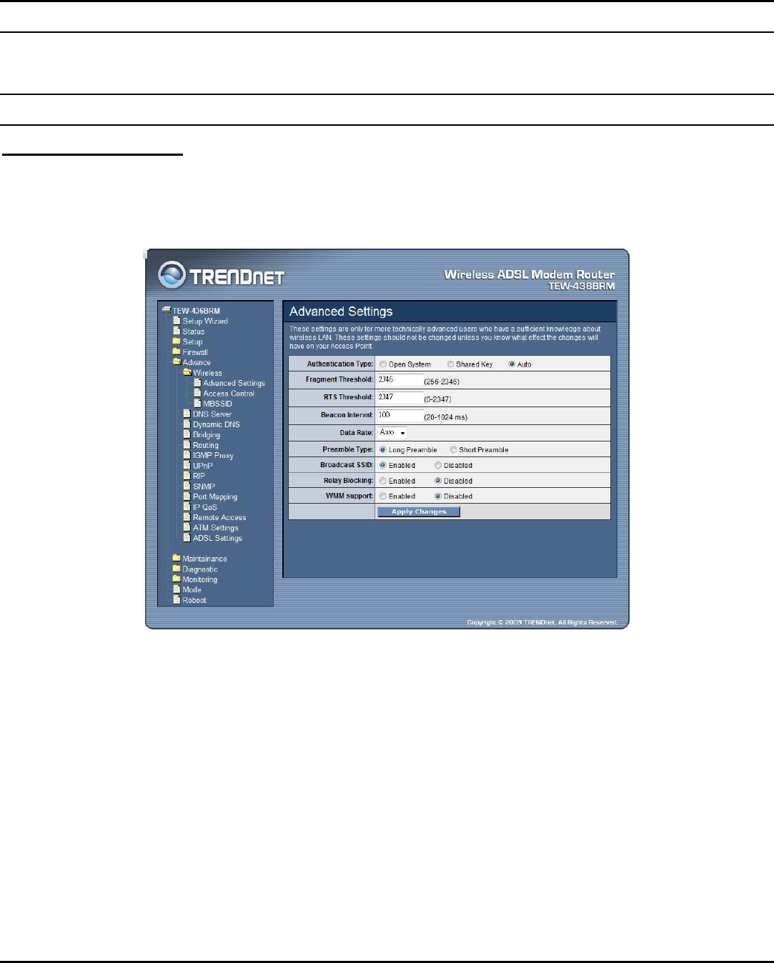
Advanced Settings
These settings are only for more technically advanced users who have a sufficient
knowledge about wireless LAN. These settings should not be changed unless you
know what effect the changes will have on your WLAN ADSL Router.
Authentication Type: Open System: Open System authentication is not required
to be successful while a client may decline to authenticate with any particular
other client. Shared Key: Shared Key is only available if the WEP option is
implemented. Shared Key authentication supports authentication of clients as
either a member of those who know a shared secret key or a member of those who
do not. IEEE 802.11 Shared Key authentication accomplishes this without the
need to transmit the secret key in clear. Requiring the use of the WEP privacy
mechanism. Auto: Auto is the default authentication algorithm. It will change its
authentication type automatically to fulfill client’s requirement.

50
Fragment Threshold: This value should remain at its default setting of 2000. It
specifies the maximum size for a packet before data is fragmented into multiple
packets. If you experience a high packet error rate, you may slightly increases the
“Fragment Threshold” value within the value range of 256 to 2346. Setting this
value too low may result in poor network performance. Only minor modifications
of this value are recommended. The default is 2346.
RTS Threshold: This value should remain at its default setting of 2000. Should
you encounter inconsistent data flow, only minor modifications are recommended.
If a network packet is smaller than the preset “RTS threshold” size, the RTS/CTS
mechanism will not be enabled. The ADSL modem (or AP) sends Request to
Send (RTS) frames to a particular receiving station and negotiates the sending of a
data frame. After receiving an RTS, the wireless station responds with a Clear to
Send (CTS) frame to acknowledge the right to begin transmission. The default is
2347.
Beacon Interval: The Beacon Interval value indicates the frequency interval of
the beacon. Enter a value between 20 and 1024. A beacon is a packet broadcast by
the ADSL modem (or AP) to synchronize the wireless network. The default is 100.
Data Rate: The rate of data transmission should be set depending on the speed of
your wireless network. You should select from a range of transmission speeds, or
you can select Auto to have the WLAN ADSL Router automatically use the
fastest possible data rate and enable the Auto-Fallback feature. Auto-Fallback will
negotiate the best possible connection speed between the AP and a wireless client.
The default setting is Auto.
Preamble Type: The Preamble Type defines the length of the CRC (Cyclic
Redundancy Check) block for communication between the AP and mobile
wireless stations. Make sure to select the appropriate preamble type. Note that
high network traffic areas should use the short preamble type. CRC is a common
technique for detecting data transmission errors.
Broadcast SSID: Select to enable or disable the Broadcast SSID feature. If this
option is enabled, the device will automatically transmit their network name
(SSID) into open air at regular interval. This feature is intended to allow clients to
dynamically discover and roam between WLANs; if this option is disabled, the
device will hide its SSID. When this is done, the station cannot directly discover
its WLAN and MUST be configure with the SSID. Note that in a home Wi-Fi
network, roaming is largely unnecessary and the SSID broadcast feature serves no
useful purpose. You should disable this feature to improve the security of your
WLAN.
51
Relay Blocking: Select to enable or disable the Relay Blocking feature. When
Relay Blocking is enabled, wireless clients will not be able to directly access
other wireless clients.
WMM support: Select to enable or disable the WMM (Wi-FI Multimedia) QoS
feature.
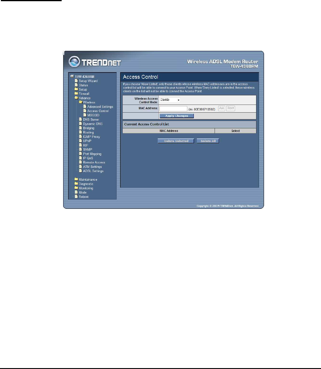
Access Control
This feature allows administrator to have access control by enter MAC address of
client stations. When Enable this function, MAC address can be added into access
control list and only those clients whose wireless MAC address are in the access
control list will be able to connect to your WLAN ADSL Router.
Wireless Access Control Mode:
Disable: Disable the wireless ACL feature;
Allow Listed: When this option is selected, no wireless clients except those
whose MAC addresses are in the current access control list will be able to connect
(to this device);
Deny Listed: When this option is selected, all wireless clients except those whose
MAC addresses are in the current access control list will be able to connect (to
this device).
MAC Address: Enter client MAC address and click “Add” button to add client
MAC address into current access control list.
52
Delete Selected: Click the “Delete Selected” button to delete the selected rule
from Current Access Control List.
Delete All: Click the “Delete All” button to delete the all of rule in the Current
Access Control List.
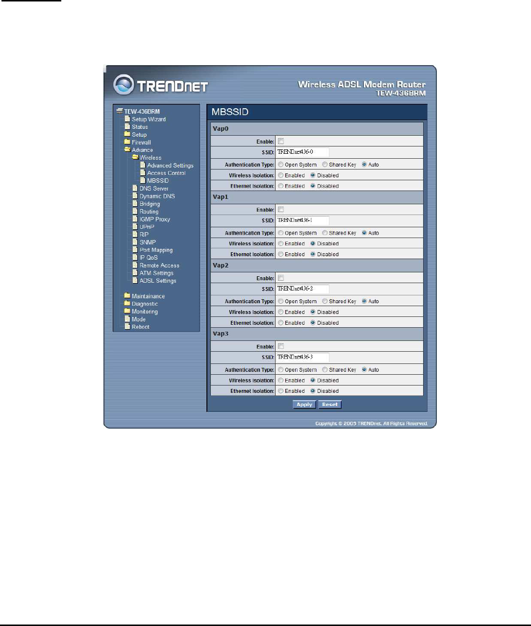
MBSSID
The WLAN ADSL Router supports up to four virtual AP (Vap0~Vap3) setting
allows wireless users connect up to the WLAN ADSL Router through up to four
different WLAN SSID and security settings.
Enable: Enable or disable the Vap (Virtual AP) setting.
SSID: Type an SSID in the text box. The SSID of any wireless device must match
the SSID typed here in order for the wireless device to access the LAN and WAN
via the WLAN ADSL Router.
Authentication Type: Open System: Open System authentication is not required
to be successful while a client may decline to authenticate with any particular
other client. Shared Key: Shared Key is only available if the WEP option is
implemented. Shared Key authentication supports authentication of clients as
either a member of those who know a shared secret key or a member of those who
53
do not. IEEE 802.11 Shared Key authentication accomplishes this without the
need to transmit the secret key in clear. Requiring the use of the WEP privacy
mechanism. Auto: Auto is the default authentication algorithm. It will change its
authentication type automatically to fulfill client’s requirement.
Wireless Isolation: Select to enable or disable the Wireless Isolation feature.
When Wireless Isolation is enabled, wireless clients will not be able to access to
the other wireless clients.
Ethernet Isolation: Select to enable or disable the Ethernet Isolation feature.
When Ethernet Isolation is enabled, wireless clients will not be able to access to
the Ethernet clients.
Dynamic DNS
Each time your device connects to the Internet, your ISP assigns a different IP
address to your device. In order for you or other users to access your device from
the WAN-side, you need to manually track the IP that is currently used. The
Dynamic DNS feature allows you to register your device with a DNS server and
access your device each time using the same host name. The Dynamic DNS page
allows you to enable/disable the Dynamic DNS feature.
Enable: Checked to enable this registration account for the DNS server.
DDNS Provider: There are two DDNS providers to be selected in order to register
your device with: DynDNS and TZO. A charge may occur depends on the service
you select.
Hostname: Domain name to be registered with the DDNS server.

54
DynDns Settings: Enter the username and password for your registered DynDNS
account.
TZO Settings: Enter the email address and key for your registered TZO account.
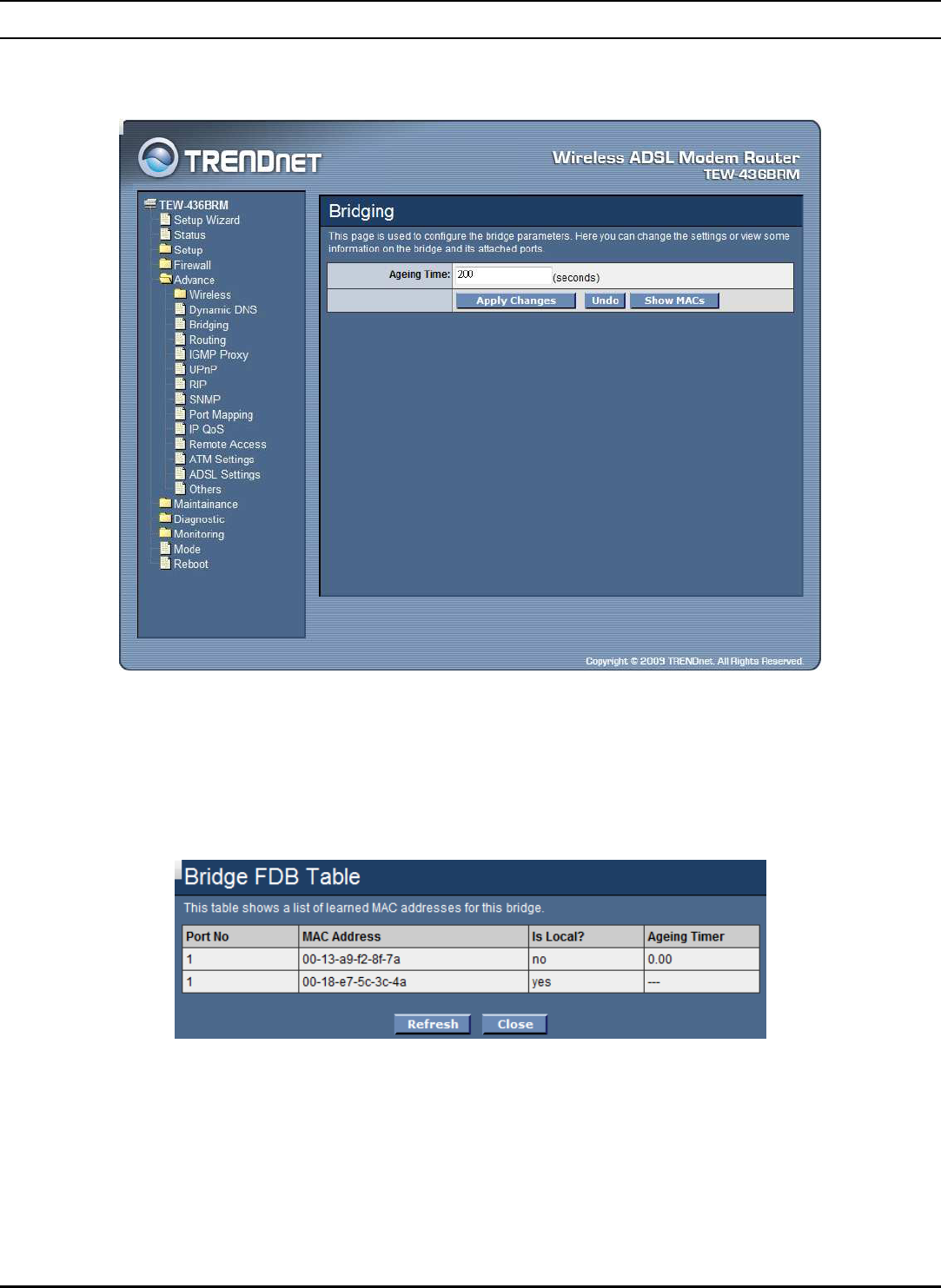
55
Bridging
This page is used to configure the bridge parameters. Here you can change the
settings or view some information on the bridge and its attached ports.
Aging Time: Set the Ethernet address ageing time, in seconds. After [Ageing Time]
seconds of not having seen a frame coming from a certain address, the bridge will
time out (delete) that address from Forwarding DataBase (fdb).
Show MACs: Click the “Show MACs” button to list MAC address in forwarding
DataBase(fdb).