TRENDNET TEW436BRM 54Mbps Wireless G ADSL 2/2+ Modem Router User Manual UG TEW 436BRM 1 0R
TRENDNET, Inc. 54Mbps Wireless G ADSL 2/2+ Modem Router UG TEW 436BRM 1 0R
TRENDNET >
Contents
- 1. Manual Part 1
- 2. Manual Part 2
Manual Part 2
56
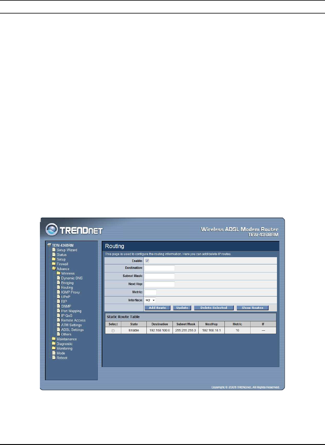
Routing
The Routing page enables you to define specific route for your Internet and
network data. Most users do not need to define routes. On a typical small home or
office LAN, the existing routes that set up the default gateways for your LAN hosts
and for the WLAN ADSL Router provide the most appropriate path for all your
Internet traffic.
On your LAN hosts, a default gateway directs all Internet traffic to the
LAN port(s) on the WLAN ADSL Router. Your LAN hosts know their
default gateway either because you assigned it to them when you modified
your TCP/IP properties, or because you configured them to receive the
information dynamically from a server whenever they access the Internet.
On the WLAN ADSL Router itself, a default gateway is defined to direct
all outbound Internet traffic to a route at your ISP. The default gateway is
assigned either automatically by your ISP whenever the device negotiates
an Internet access, or manually by user to setup through the configuration.
You may need to define routes if your home setup includes two or more networks
or subnets, if you connect to two or more ISP services, or if you connect to a
remote corporate LAN.
Enable: Checked to enable the selected route or route to be added.
Destination: The network IP address of the subnet. The destination can be
specified as the IP address of a subnet or a specific host in the subnet. It can also be
57
specified as all zeros to indicate that this route should be used for all destinations
for which no other route is defined (this is the route that creates the default
gateway).
Subnet Mask: The network mask of the destination subnet. The default gateway
uses a mask of 0.0.0.0.
Next Hop: The IP address of the next hop through which traffic will flow towards
the destination subnet.
Metric: Defines the number of hops between network nodes that data packets
travel. The default value is 0, which means that the subnet is directly one hop away
on the local LAN network.
Interface: The WAN interface to which a static routing subnet is to be applied.
Add Router: Click the “Add Router” button to add a user-defined destination route.
Update: Click the “Update” button to modify the selected rule form the Static
Route Table.
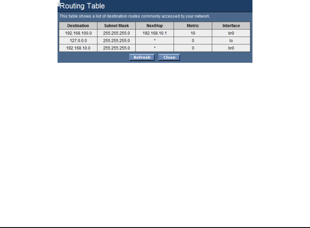
Show Routes: Click the “Show Routes” to display the routing table of the WLAN
ADSL Router.
58
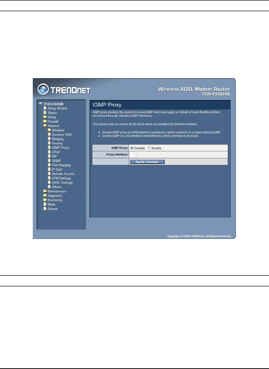
IGMP Proxy
IGMP proxy enables the system to issue IGMP host messages on behalf of hosts
that the system discovered through standard IGMP interfaces.
The system acts as a proxy for its hosts when you enable it by doing the follows:
Enable IGMP proxy on WAN interface (upstream), which connects to a
router running IGMP.
Enable IGMP on LAN interface (downstream), which connects to its hosts.
IGMP Proxy: Select to enable or disable the IGMP proxy feature on the WLAN
ADSL Router.
Proxy Interface: The upstream WAN interface is selected here.
UPnP
The WLAN ADSL Router supports a control point for Universal Plug and Play
(UPnP) version 1.0, and supports two key features: NAT Traversal and Device
Identification. This feature requires one active WAN interface. In addition, the host
should support this feature. In the presence of multiple WAN interfaces, select an
interface on which the incoming traffic is present. With NAT Traversal, when an
UPnP command is received to open ports in NAT, the application translates the
request into system commands to open the ports in NAT and the firewall. The
interface to open the ports on is given to UPnP when it starts up and is part of the
59
configuration of the application. For Device Identification, the application will send
a description of the WLAN ADSL Router as a control point back to the host
making the request.
UPnP: Select to enable or disable the UPnP feature on the WLAN ADSL Router.
WAN Interface: Select WAN interface that will use UPnP from the drop-down
lists.
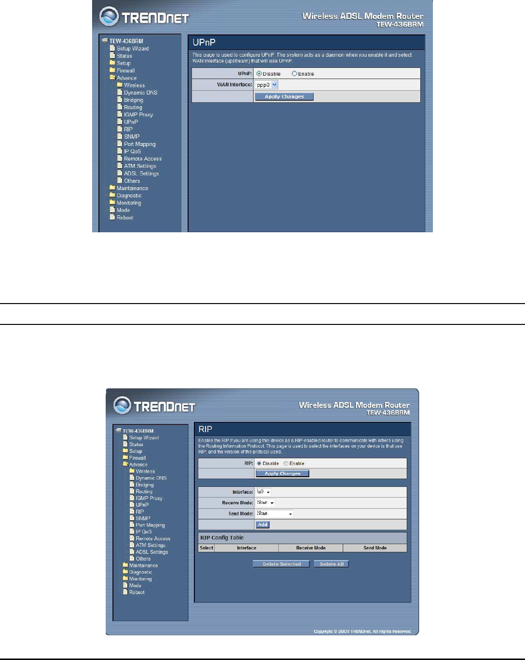
RIP
Enable the RIP if you are using this device as a RIP-enabled router to communicate
with others using the Routing Information Protocol. This page is used to select the
interfaces on your device is that use RIP, and the version of the protocol used.
60
RIP: Select to enable or disable the RIP feature on the WLAN ADSL Router.
Receive Mode: Select which RIP version to be used for RIP listening, RIP1, RIP2
or Both (RIP1+RIP2), Selected None to disable the RIP listening.
Send Mode: Select which RIP version to be used for RIP sending, RIP1, RIP2 or
Both (RIP1+RIP2), Selected None to disable the RIP sending.
Delete Selected: Click the “Delete Selected” button to delete the selected RIP
config from RIP Config Table.
Delete All: Click the “Delete All” button to delete the all of rule in the RIP config
from RIP Config Table.
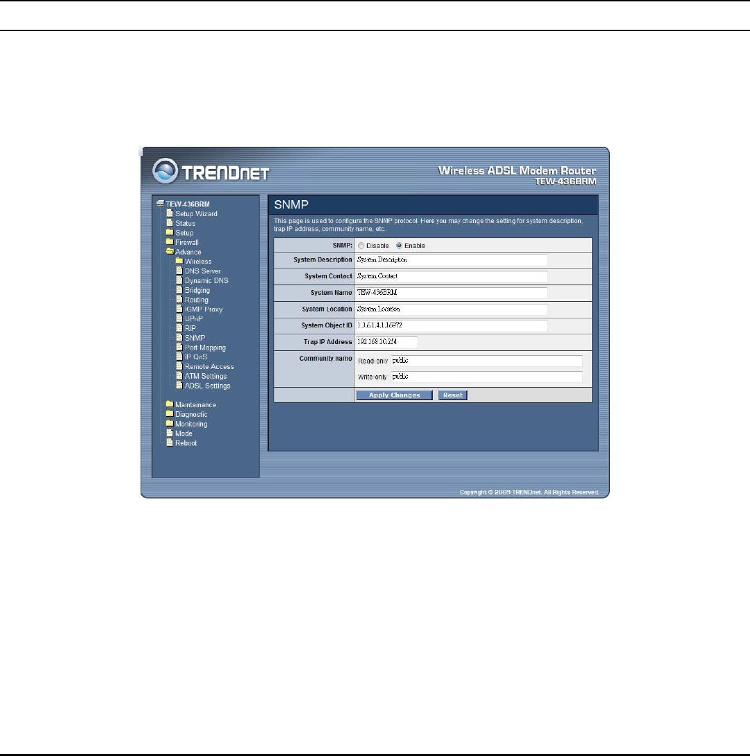
SNMP
Simple Network Management Protocol (SNMP) is a troubleshooting and
management protocol that uses the UDP protocol on port 161 to communicate
between clients and servers. The DSL device can be managed locally or remotely
by SNMP protocol.
SNMP: Enable or Disable the SNMP feature on the WLAN ADSL Router.
System Description: System description of the WLAN ADSL Router.
System Contact: Contact person and/or contact information for the WLAN ADSL
Router.
System Name: An administratively assigned name for the WLAN ADSL Router.
System Location: The physical location of the WLAN ADSL Router.
System Object ID: Vendor Object Identifier. The vendor’s authoritative
identification of the network management subsystem contained in the entity.
61
Trap IP Address: Destination IP address of the SNMP trap.
Community name:
Read-only: Name of the read-only community. This read-only community
allows read operation to all objects in the MIB.
Write-only: Name of the write-only community. This write-only community
allows write operation to the objects defines as read-writable in the MIB.
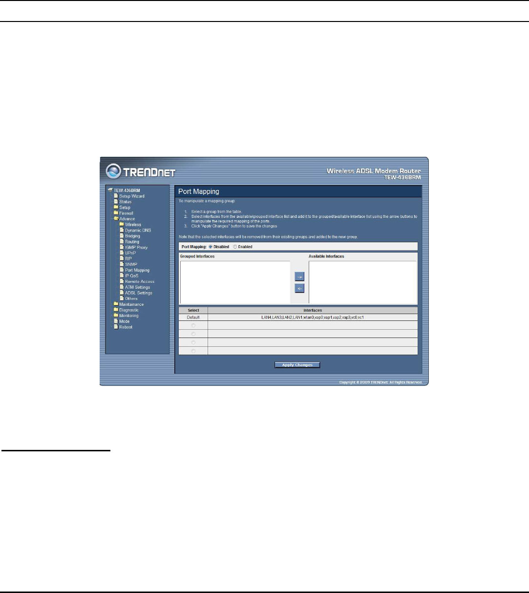
Port Mapping
The WLAN ADSL Router provides multiple interface groups. Up to five interface
groups are supported including one default group. The LAN and WAN interfaces
could be included. Traffic coming from one interface of a group can only be flowed
to the interfaces in the same interface group. Thus, the WLAN ADSL Router can
isolate traffic from group to group for some application. By default, all the
interfaces (LAN and WAN) belong to the default group, and the other four groups
are all empty. It is possible to assign any interface to any group but only one group.
Port Mapping: Select to enable or disable the interface group feature. If disabled,
all interfaces belong to the default group.
Interface Group
To manipulate a mapping group:
1. Select a group from the table.
2. Select interfaces from the available/grouped interface list and add it to the
grouped/available interface list using the arrow buttons to manipulate the
required mapping of the ports.
3. Click “Apply Changes” button to save the changes.
62
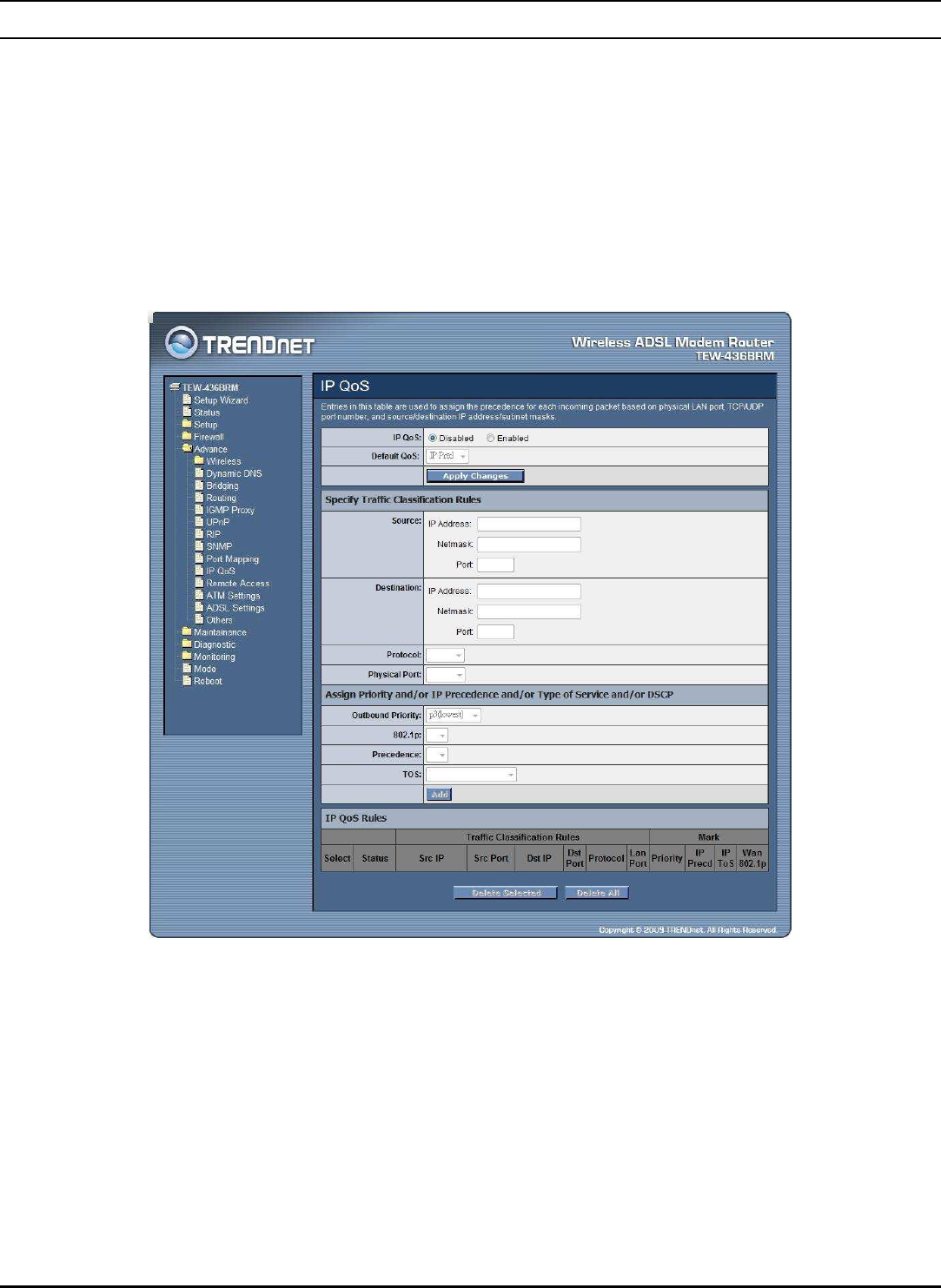
IP QoS
The WLAN ADSL Router provides a control mechanism that can provide different
priority to different users or data flows. The QoS is enforced by the QoS rules in
the QoS table. A QoS rule contains two configuration blocks: Traffic Classification
and Action. The Traffic Classification enables you to classify packets on the basis
of various fields in the packet and perhaps the physical ingress port. The Action
enables you to assign the strictly priority level for and mark some fields in the
packet that matches the Traffic Classification rule. You can configure any or all
field as needed in these two QoS blocks for a QoS rule.
IP QoS: Select to enable or disable the IP QoS function.
Default QoS: Select the QoS method IP Pred or 802.1p from list.
Source: The IP address, subnet mask and port number of the traffic source.
Destination: The IP address, subnet mask and port number of the traffic destination.
Protocol: The selections are TCP, UDP, ICMP and the blank for none. This field is
required if the source port or destination port has been entered.
Physical Port: The incoming ports. The selections include LAN ports, wireless
port, and the blank for not applicable.
63
Outbound Priority: The priority level for the traffic that matches this
classification rule. The possible selections are (in the descending priority): p0, p1,
p2, p3.
802.1p: Select this field to mark the 3-bit user-priority field in the 802.1p header of
the packet that match this classification rule. Note that this 802.1p marking is
workable on a given PVC channel only if the VLAN tag is enabled in this PVC
channel.
Precedence: Select this field to mark the IP precedence bits in the packet that
match this classification rule.
TOS: Select this field to mark the IP TOS bits in the packet that match this
classification rule.
Add: Click to add the QoS rule to the UP QoS Rules.
Delete Selected: Click the “Delete Selected” button to delete the selected QoS rule
from the IP QoS Rules.
Delete All: Click the “Delete All” button to delete the all of rule in the IP QoS
Rules.
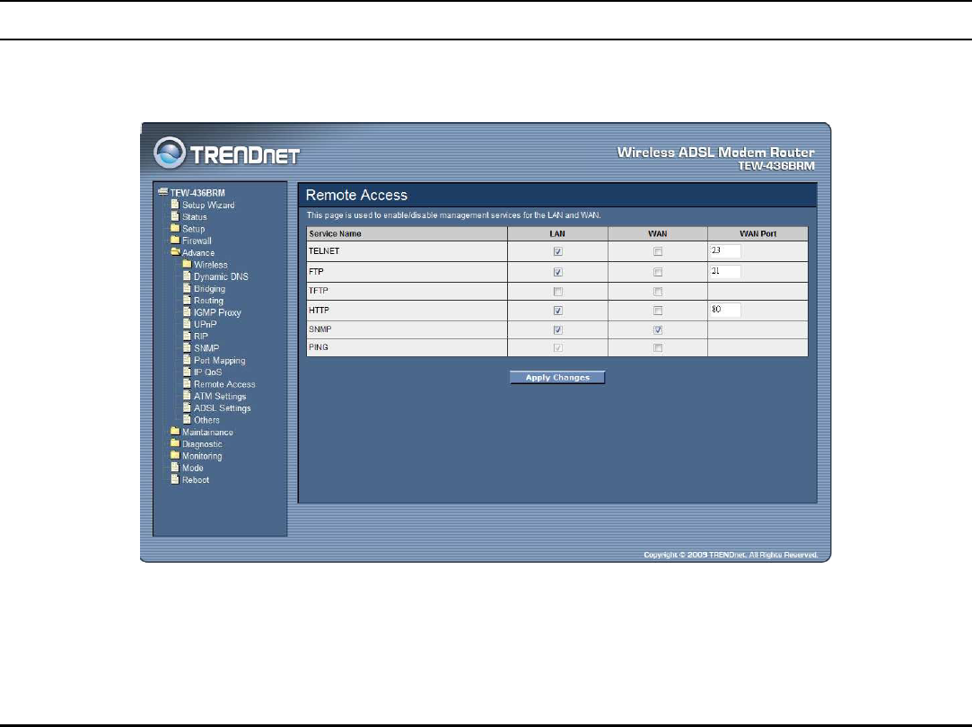
Remote Access
The Remote Access function can secure remote host access to your DSL device
from LAN and WLAN interfaces for some services provided by the DSL device.
LAN: Checked the services on the LAN column to allows the services access from
LAN side.
64
WAN: Checked the services on the WAN column to allows the services access
from WAN side.
WAN Port: This field allows the user to specify the port of the corresponding
service. Take the HTTP service for example; when it is changed to 8080, the HTTP
server address for the WAN side is http://dsl_addr:8080, where the dsl_addr is the
WAN side IP address of the WLAN ADSL Router.
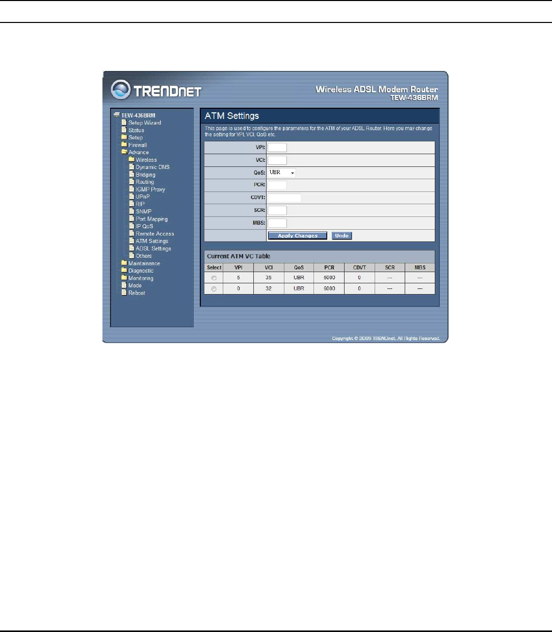
ATM Settings
This page is used to configure the parameters for the ATM of your ADSL Router.
Here you may change the setting for VPI, VCI, QoS etc.
VPI: Virtual Path Identifier. This is read-only field and is selected on the Select
column in the Current ATM VC Table.
VCI: Virtual Channel Identifier. This is read-only field and is selected on the Select
column in the Current ATM VC Table. The VCI, together with VPI, is used to
identify the next destination of a cell as it passes through to the ATM switch.
QoS: Quality of Server, a characteristic of data transmission that measures how
accurately and how quickly a message or data is transferred from a source host to a
destination host over a network. The four QoS options are:
UBR (Unspecified Bit Rate): When UBR is selected, the SCR and MBS
fields are disabled.
CBR (Constant Bit Rate): When CBR is selected, the SCR and MBS
fields are disabled.
65
nrt-VBR (non-real-time Variable Bit Rate): When nrt-VBR is selected,
the SCR and MBS fields are enabled.
rt-VBR (real-time Variable Bit Rate): When rt-VBR is selected, the SCR
and MBS fields are enabled.
PCR: Peak Cell Rate, measured in cells/sec., is the cell rate which the source may
never exceed.
CDVT: Cell Delay Variation Tolerance, is a QoS parameter in ATM network for
managing traffic that is specified when a connection is set up. In CBR
transmissions, CDVT determines the level of jitter that is tolerable for the data
samples taken by the PCR.
SCR: Sustained Cell Rate, measured in cells/sec., is the average cell rate over the
duration of the connection.
MBS: Maximum Burst Size, a traffic parameter that specifies the maximum
number of cells that can be transmitted at the peak cell rate.
Apply Changes: Click to set new PVC QoS mode for the selected PVC. New
parameters will take effect after save into flash memory and reboot the system.
Undo: Discard your settings.
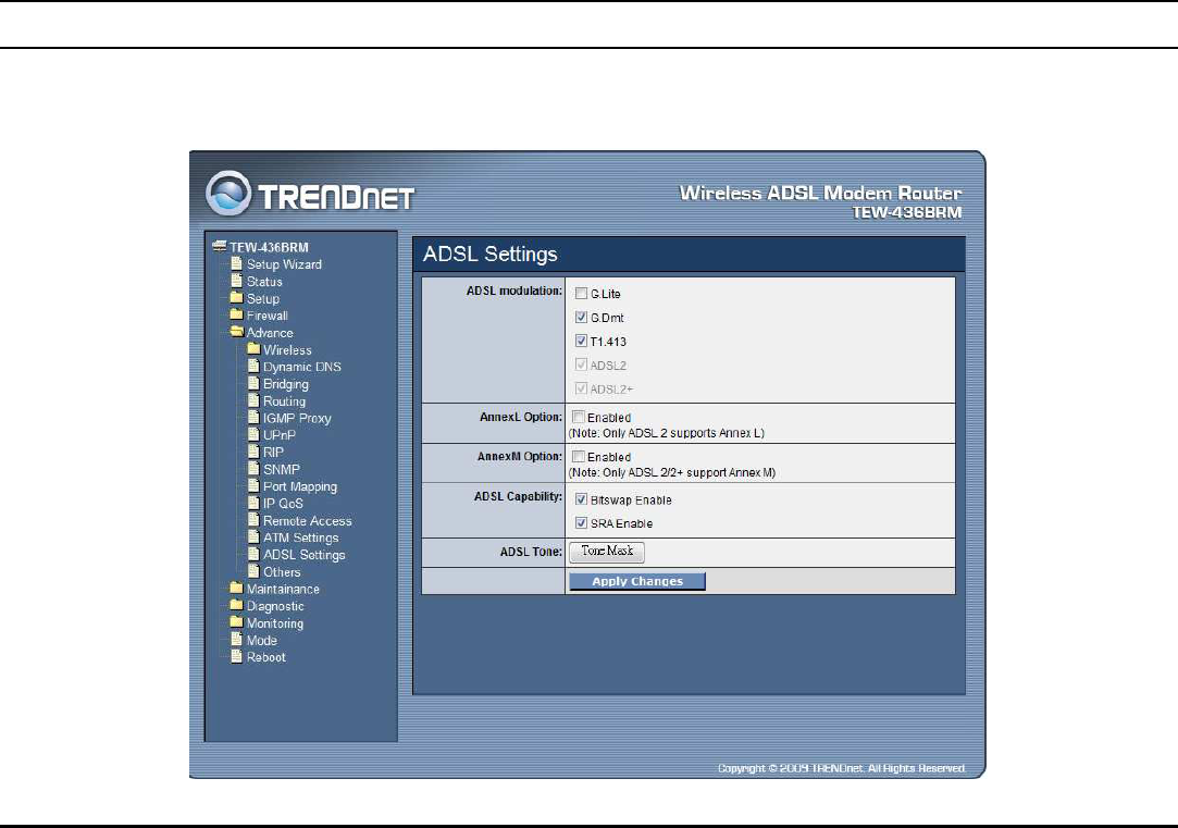
ADSL Settings
The ADSL setting page allows you to select any combination of DSL training
modes.
66
ADSL modulation: Choose preferred xDSL standard protocols, defined by ISP.
G.lite: G.992.2 Annex A
G.dmt: G.992.1 Annex A
T1.413: T1.413 issue #2
ADSL2: G.992.3 Annex A
ADSL2+: G.992.5 Annex A
AnnexL Option: Checked to Enable the ADSL2/ADSL2+ Annex L capability.
AnnexM Option: Checked to Enable the ADSL2/ADSL2+ Annex M capability.
ADSL Capability: Checked to enable the bitswap capability or SRA capability.
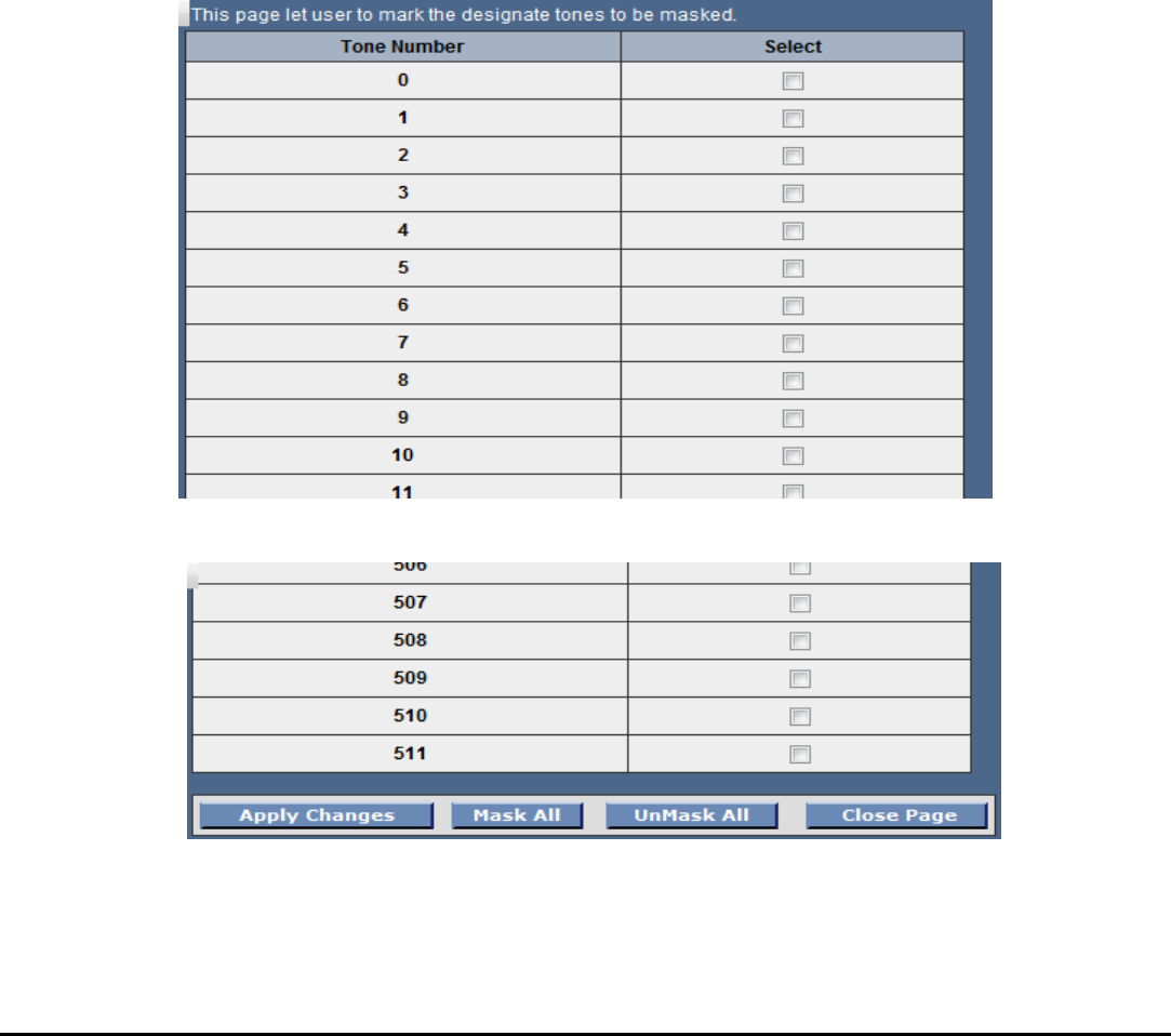
ADSL Tone: Click the “ADSL Tone” button to choose tones to be masked.
Masked tones will not carry any data.
:
.:
Apply Changes: Click to save the setting to the configuration and the modem
will be retrained.
67
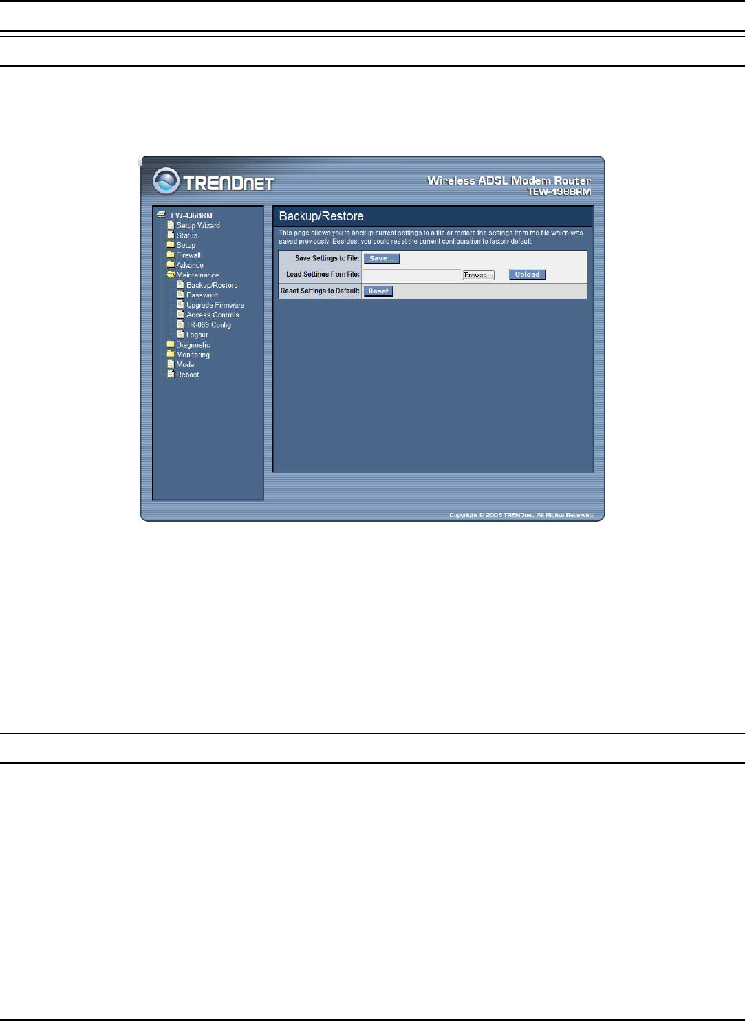
Maintainance
Backup/Restore
This page allows you to backup current settings to a file or restore the settings from
the file which was saved previously. Besides, you could reset the current
configuration to factory default.
Save Setting to File: Click the “Save Setting to File” button to save current settings
of the WLAN ADSL Router to local computer.
Load Setting from File: Click the “Browse” button and selected a saved setting
file from file browse window then click “Upload” button to loading the saved
setting to the WLAN ADSL Router.
Reset Settings to Default: Click the “Reset” button to reset the settings to factory
default settings.
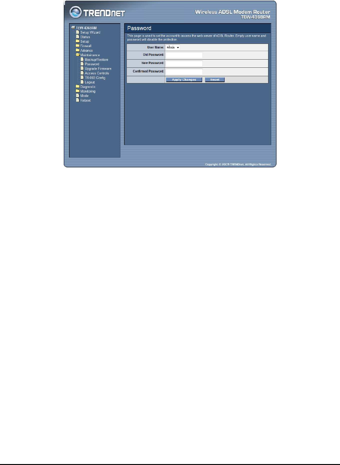
Password
The first time you log into the WLAN ADSL Router, you use the default password.
There are two-level logins: admin and user. The admin and user password
configuration allows you to change the password for administrator and user.
68
User Name: Selection of user levels are: admin and user.
Old Password: Enter the old password for this selected login.
New Password: Enter the new password here.
Confirmed Password: Enter the new password here again to confirm.
69
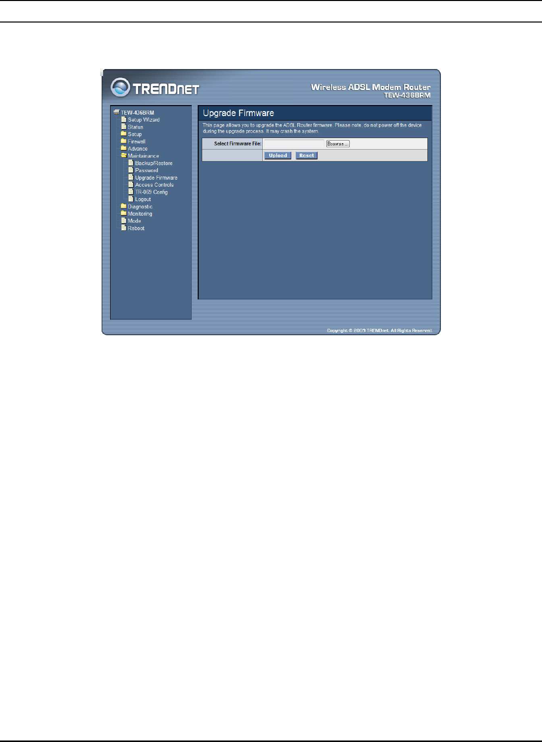
Upgrade Firmware
This page allows you to upgrade the WLAN ADSL Router firmware. Please note,
do not power off the device during the upgrade process. It may crash the system.
To upgrade the firmware for the DSL device:
Click the Browse button to select the firmware file.
Confirm your selection.
Click the Upload button to start upgrading.
IMPORTANT! Do not turn off your DSL device or click the Reset button
while this procedure is in progress.
70
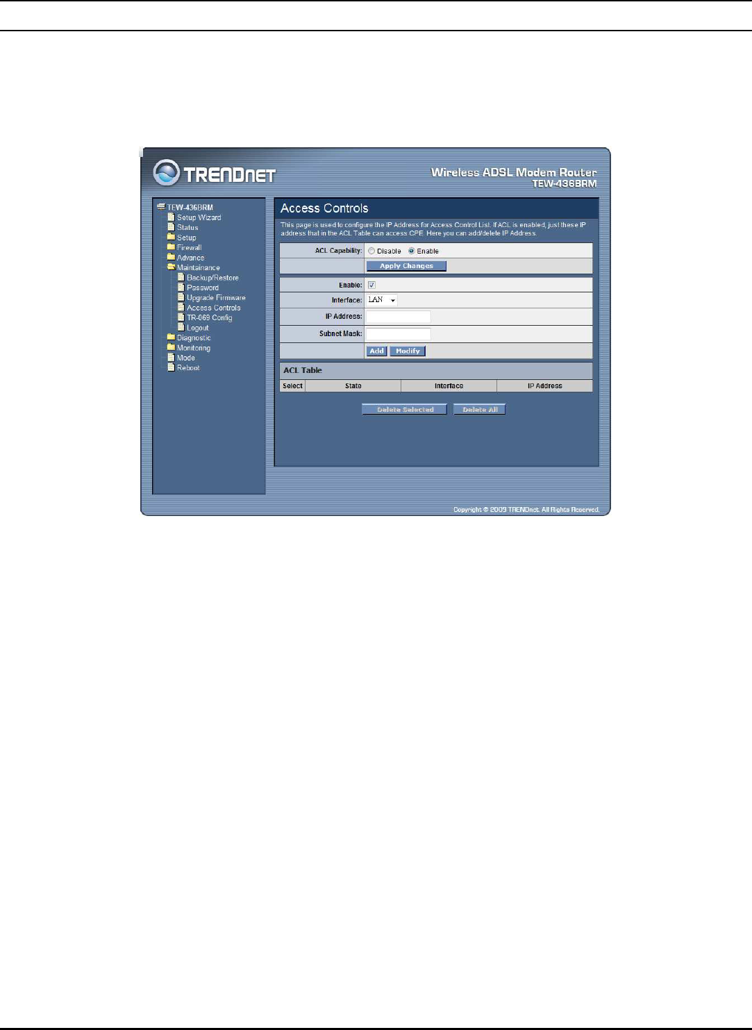
Access Controls
The Access Control List (ACL) is a list of permissions attached to the WLAN
ADSL Router. The list specifies who is allowed to access this device. If ACL is
enabled, all hosts cannot access this device except for the hosts with IP address in
the ACL table.
ACL Capability: Enable or Disable the SNMP feature on the WLAN ADSL
Router.
Enable: Checked to enable the selected route or route to be added.
Interface: Select the interface domain: LAN or WAN.
IP Address: Enter the IP address that allow access to this device.
Subnet Mask: Type the subnet mask in the text box.
Add: Click to add the ACL rule to the ACL table.
Modify: Click the “Modify” button to modify the selected rule form the ACL Table.
Delete Selected: Click the “Delete Selected” button to delete the selected rule from
ACL Table.
Delete All: Click the “Delete All” button to delete the all of rule in the ACL Table.
71
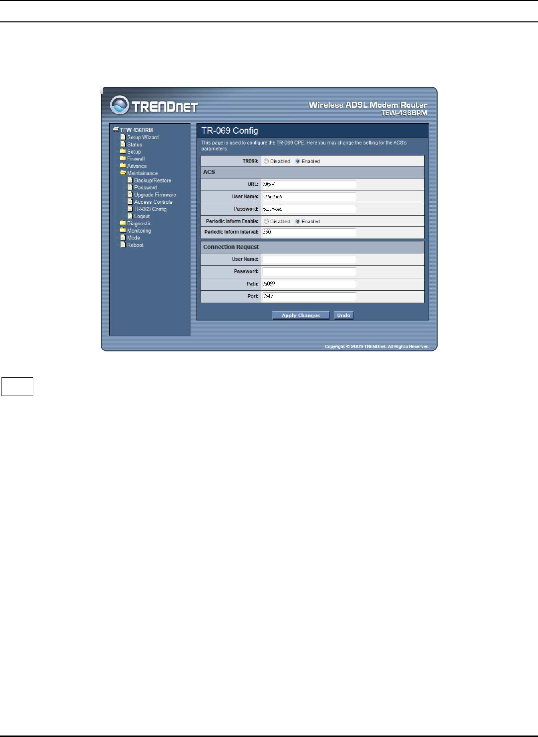
TR-069 Config
TR-069 is a protocol for communication between a CPE and Auto-Configuration
Server (ACS). The CPE TR-069 configuration should be well defined to be able to
communicate with the remote ACS.
TR069: Enable or Disable the TR-069 feature on the WLAN ADSL Router.
ACS
URL: Enter the ACS URL here.
User Name: The username the WLAN ADSL Router should use when
connecting to the ACS.
Password: The password the WLAN ADSL Router should use when connecting
to the ACS.
Periodic Inform Enable: When this field is enabled, the WLAN ADSL Router
will send an Inform RPC to the ACS server at the system startup, and will
continue to send it periodically at an interval defined in Periodic Inform Interval
field; When this field is disabled, the WLAN ADSL Router will only send
Inform RPC to the ACS server once at the system startup.
Periodic Inform Interval: Time interval in second to send Inform RPC.
72
Connection Request
User Name: The username the remote ACS should use when connecting to this
device.
Password: The password the remote ACS should use when connecting to this
device.
Path: The path of the device ConnectionRequestURL. The device
ConnectionRequestURL should be configured based on the Device_IP, Path and
Port as follows: http://Device_IP:Port/Path.
Port: The port of the device ConnectionRequestURL.
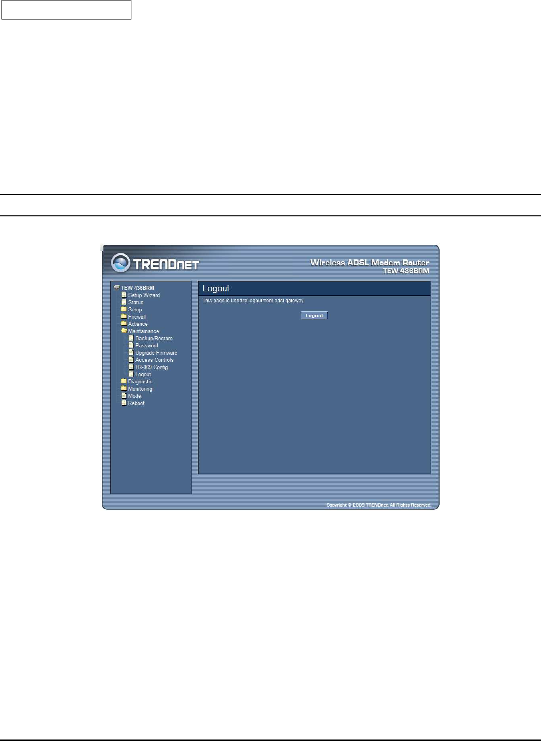
Logout
This page is used to logout from ADSL gateway.
Click the “Logout” button to logout from the WLAN ADSL Router.
73
Diagnostic
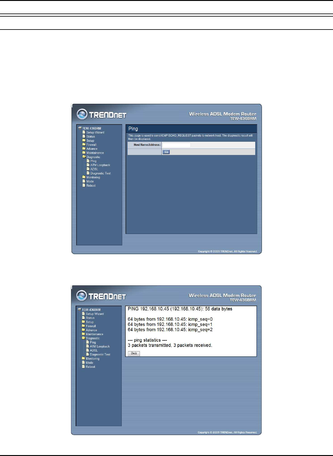
Ping
Once you have your WLAN ADSL Router configured, it is a good idea to make
sure you can ping the network. A ping command sends a message to the host you
specify. If the host receives the message, it sends messages in reply. To use it, you
must know the IP address of the host you are trying to communicate with and enter
the IP address in the Host Address field. Click “Go” button to start the ping
command, the ping result will then be shown in this page.
Go: Click “Go” button to start the ping command, the ping result will then be
shown in this page.
74
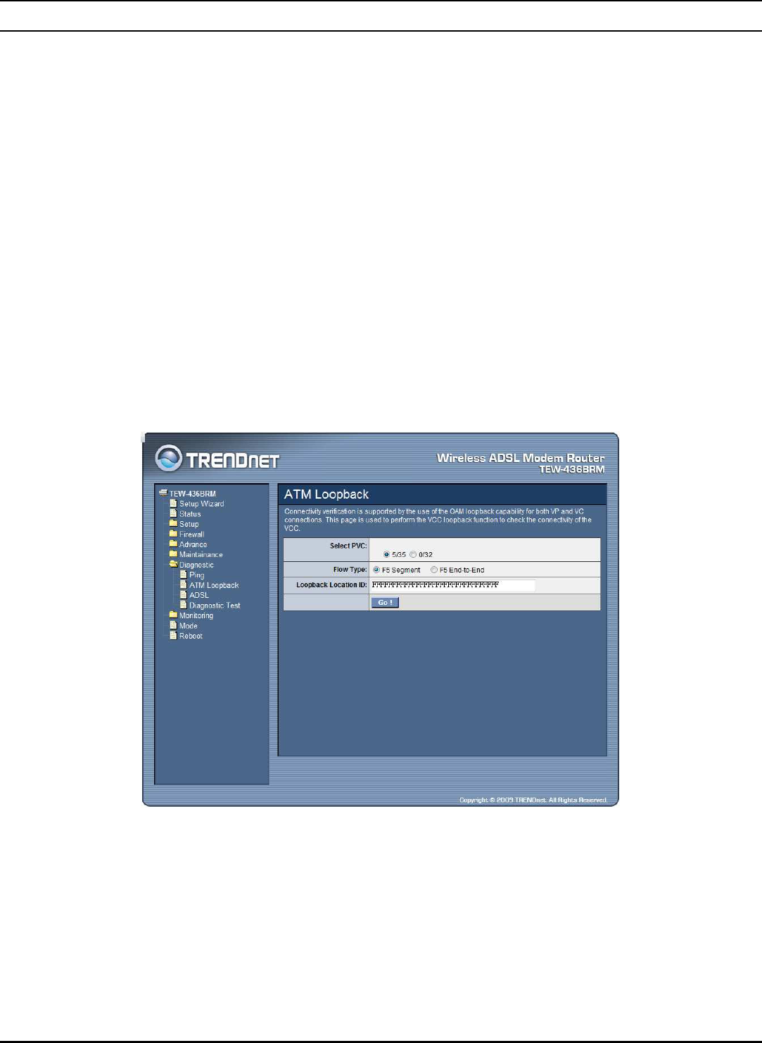
ATM Loopback
In order to isolate the ATM interface problems, you can use ATM OAM loopback
cells to verify connectivity between VP/VC endpoints, as well as segment
endpoints within the VP/VC. ATM uses F4 and F5 cell flows as follows:
F4: used in VPs.
F5: used in VCs.
An ATM connection consists of a group of points. This OAM implementation
provides management for the following points:
Connection endpoint: the end of a VP/VC connection where the ATM
cell are terminated.
Segment endpoint: the end of a connection segment.
This page allows you to use ATM ping, which generates F5 segment and end-to-
end loop-back cells to test the reach ability of a segment endpoint or a connection
endpoint.
Select PVC: Select the PVC channel you want to do the loop-back diagnostic.
Flow Type: The ATM OAM flow type. The selection can be F5 Segment or F5
End-to-End.
Loopback Location ID: The loop-back location ID field of the loop-back cell. The
default value is all 1s (ones) to indicate the endpoint of the segment or connection.
75
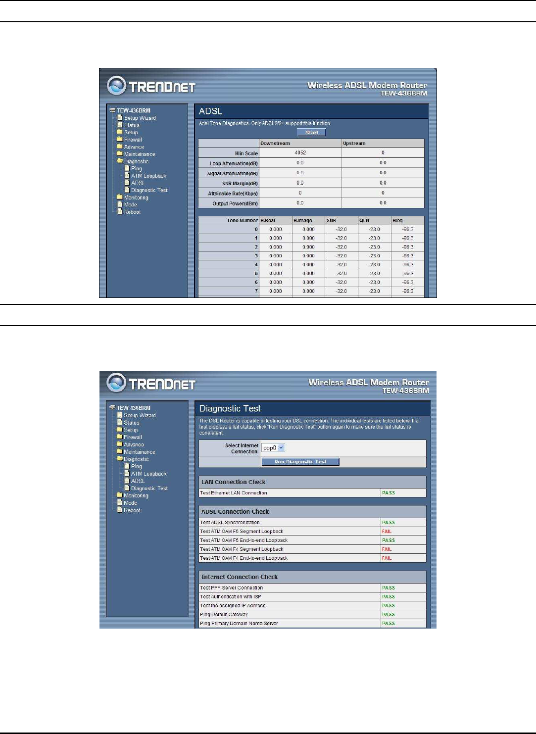
ADSL
This page shows the ADSL diagnostic result. Click “Start” button to start the ADSL
diagnostic.
Diagnostic Test
The Diagnostic Test page shows the test results for the connectivity of the physical
layer and protocol layer for both LAN and WAN sides.
Select Internet Connection: The available WAN side interfaces are listed. You
have to select one for the WAN side diagnostic.
Run Diagnostic Test: Click the “Run Diagnostic Test” button to start the
diagnostic test.
76
Monitoring
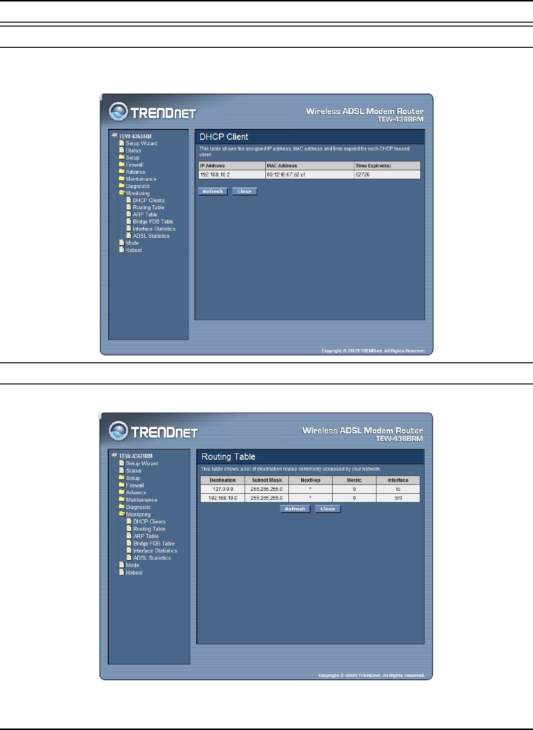
DHCP Clients
This table shows the assigned IP address, MAC address and time expired for each
DHCP leased client.
Routing Table
This table shows a list of destination routes commonly accessed by your network.
77
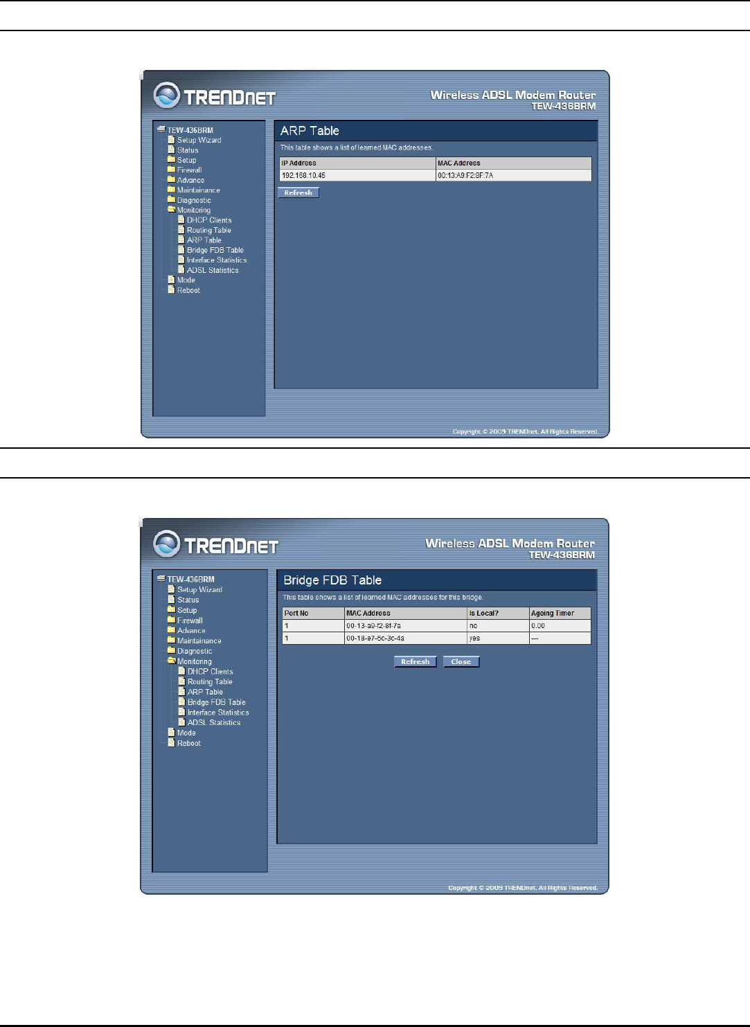
ARP Table
This table shows a list of learned MAC addresses.
Bridge FDB Table
This table shows a list of learned MAC addresses for this bridge.
78
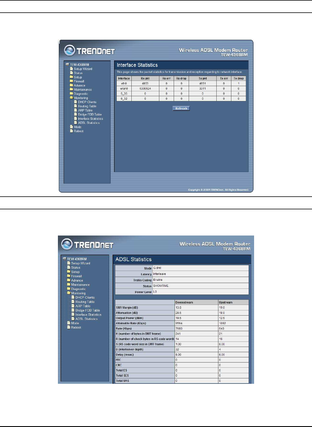
Interface Statistics
This page shows the packet statistics for transmission and reception regarding to
network interface.
ADSL Statistics
This page shows the packet statistics for transmission and reception regarding to the
ADSL.
79
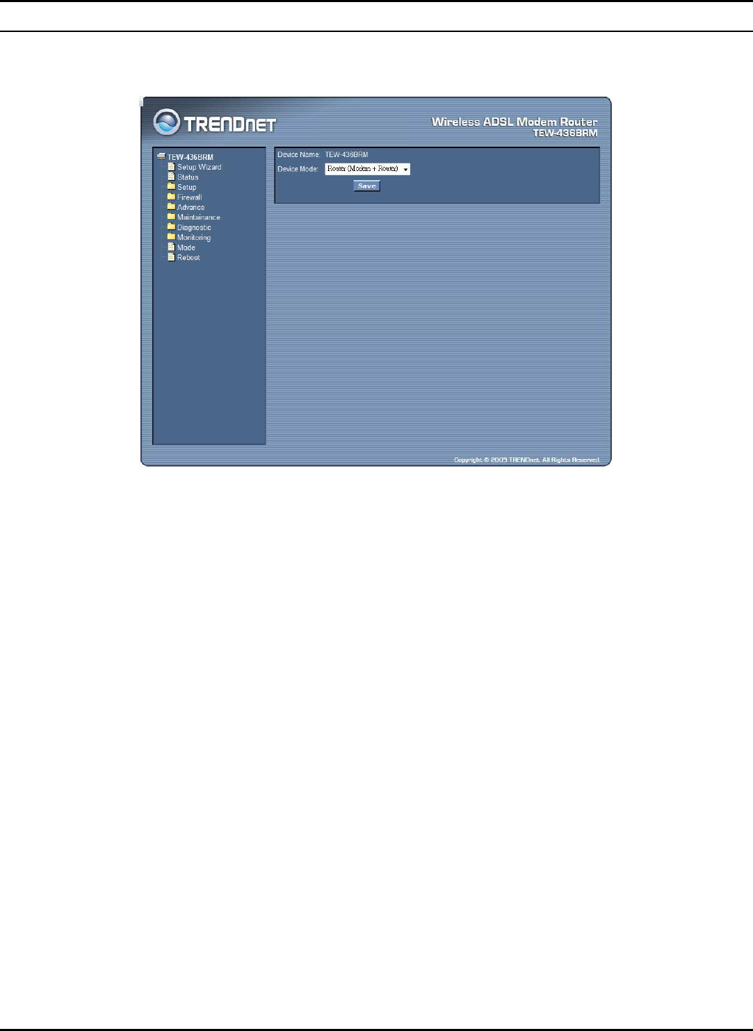
Mode
This page explains configuration and operation when in "Router" or "Modem"
mode.
Device Mode: There are two modes available on the Mode screen.
Router: Both the ADSL Modem and the Router features are operational.
In this mode, this device can provide shared Internet Access to all your
LAN users. Also, by default, it acts a DHCP Server, providing an IP
address and related information to all Wireless and LAN users.
Modem: Only the ADSL Modem component is operational. All Router
features are disabled. This device is "transparent" - it does not perform
any operations or make any changes to the network traffic passing through
it. You need to have a DHCP Server on your LAN to provide IP addresses
to the Wireless clients using this Access Point.
80
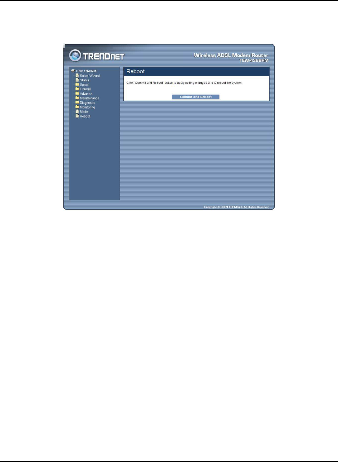
Reboot
Click "Commit and Reboot" button to apply setting changes and to reboot the
WLAN ADSL Router.

81
TECHNICAL SPECIFICATIONS
General
Standards Compliant with ADSL standards: ANSI T1.413 Issue2, G.992.1
(G.dmt, Annex A), G.992.2 (G.lite)
Compliant with ADSL2 standard: G.992.3 (G.dmt.bis)
Compliant with ADSL2+ standard: G.992.5 Annex A
IEEE 802.11b & 802.11g Wireless LAN
IEEE 802.3u 10/100Base TX Fast Ethernet
Protocol WLAN:
CSMA/CA
ATM & PPP:
VC and LLC Multiplexing, Bridged/Routed Ethernet over
ATM (RFC1483/2684), Classical IP over ATM(RFC-1577),
OAM F4/F5 loop-back, PPP over ATM (RFC2364), PPP over
Ethernet (RFC2516), ATM TrafficShaping QoS(UBR, CBR,
rt-VBR, nrt-VBR)
LAN/WAN Network:
TCP/IP, NAT, HTTP, DHCP Server/Relay/Client, DDNS,
DNS Proxy
Radio Technology DSSS/OFDM
Data Transfer
Rate 802.11g mode: up to 54Mbps (auto sense)
802.11b mode: up to 11Mbps (auto sense)
Ethernet: 10Mbps (half duplex), 20Mbps (full-duplex)
Fast Ethernet: 100Mbps (half duplex), 200Mbps (full- duplex)
Receiver
Sensitivity 802.11g: -65dBm typical @ 54Mbps
802.11b: -80dBm typical @ 11Mbps
TX Power
(Average power)
802.11g: 14dBm typical
802.11b: 14.5dBm typical
Network Cables 10BASE-T: 2-pair UTP Cat. 3,4,5 (100 m), EIA/TIA- 568 100-
ohm STP (100 m)
100BASE-TX: 2-pair UTP Cat. 5 (100 m), EIA/TIA-568 100-ohm
STP (100 m)
Frequency Range 2412 ~ 2484 MHz ISM band
Modulation
Schemes DBPSK/DQPSK/CCK/OFDM
Security 64/128-bits WEP Encryption; WPA, WPA-PSK, WPA2, WPA2-
PSK, WPS
Management Web based Configuration, Command Line Interface (CLI) via
Telnet, TR-069 Remote Management, SNMP Support
Channels 1~11 Channels (FCC) 1~13 Channels (ETSI)
Number of Ports LAN: 4 x 10/100Mbps Auto-MDIX Fast Ethernet port
WAN: 1 x RJ11Port

82
Physical and Environmental
DC inputs 12VDC 1A
Power
Consumption 6.5watts (max)
Temperature Operating: 0
o
C ~ 40
o
C, Storage: -10
o
~ 70
o
C
Humidity Operating: 10% ~ 90%, Storage: 5% ~ 90%
Dimensions 195 x 120 x 30mm
EMI: FCC part 15, FCC part 68, CE

83
LIMITED WARRANTY
TRENDnet warrants its products against defects in material and workmanship, under normal use and service, for the
following lengths of time from the date of purchase.
TEW-436BRM – 3 Years Warranty
AC/DC Power Adapter, Cooling Fan, and Power Supply carry 1 year warranty.
If a product does not operate as warranted during the applicable warranty period, TRENDnet shall reserve the right, at
its expense, to repair or replace the defective product or part and deliver an equivalent product or part to the customer.
The repair/replacement unit’s warranty continues from the original date of purchase. All products that are replaced
become the property of TRENDnet. Replacement products may be new or reconditioned. TRENDnet does not issue
refunds or credit. Please contact the point-of-purchase for their return policies.
TRENDnet shall not be responsible for any software, firmware, information, or memory data of customer contained in,
stored on, or integrated with any products returned to TRENDnet pursuant to any warranty.
There are no user serviceable parts inside the product. Do not remove or attempt to service the product by any
unauthorized service center. This warranty is voided if (i) the product has been modified or repaired by any
unauthorized service center, (ii) the product was subject to accident, abuse, or improper use (iii) the product was
subject to conditions more severe than those specified in the manual.
Warranty service may be obtained by contacting TRENDnet within the applicable warranty period and providing a copy
of the dated proof of the purchase. Upon proper submission of required documentation a Return Material Authorization
(RMA) number will be issued. An RMA number is required in order to initiate warranty service support for all TRENDnet
products. Products that are sent to TRENDnet for RMA service must have the RMA number marked on the outside of
return packages and sent to TRENDnet prepaid, insured and packaged appropriately for safe shipment. Customers
shipping from outside of the USA and Canada are responsible for return shipping fees. Customers shipping from outside
of the USA are responsible for custom charges, including but not limited to, duty, tax, and other fees.
WARRANTIES EXCLUSIVE: IF THE TRENDNET PRODUCT DOES NOT OPERATE AS WARRANTED ABOVE, THE CUSTOMER’S
SOLE REMEDY SHALL BE, AT TRENDNET’S OPTION, REPAIR OR REPLACE. THE FOREGOING WARRANTIES AND REMEDIES
ARE EXCLUSIVE AND ARE IN LIEU OF ALL OTHER WARRANTIES, EXPRESSED OR IMPLIED, EITHER IN FACT OR BY
OPERATION OF LAW, STATUTORY OR OTHERWISE, INCLUDING WARRANTIES OF MERCHANTABILITY AND FITNESS FOR A
PARTICULAR PURPOSE. TRENDNET NEITHER ASSUMES NOR AUTHORIZES ANY OTHER PERSON TO ASSUME FOR IT ANY
OTHER LIABILITY IN CONNECTION WITH THE SALE, INSTALLATION MAINTENANCE OR USE OF TRENDNET’S PRODUCTS.
TRENDNET SHALL NOT BE LIABLE UNDER THIS WARRANTY IF ITS TESTING AND EXAMINATION DISCLOSE THAT THE
ALLEGED DEFECT IN THE PRODUCT DOES NOT EXIST OR WAS CAUSED BY CUSTOMER’S OR ANY THIRD PERSON’S MISUSE,
NEGLECT, IMPROPER INSTALLATION OR TESTING, UNAUTHORIZED ATTEMPTS TO REPAIR OR MODIFY, OR ANY OTHER
CAUSE BEYOND THE RANGE OF THE INTENDED USE, OR BY ACCIDENT, FIRE, LIGHTNING, OR OTHER HAZARD.
LIMITATION OF LIABILITY: TO THE FULL EXTENT ALLOWED BY LAW TRENDNET ALSO EXCLUDES FOR ITSELF AND ITS
SUPPLIERS ANY LIABILITY, WHETHER BASED IN CONTRACT OR TORT (INCLUDING NEGLIGENCE), FOR INCIDENTAL,
CONSEQUENTIAL, INDIRECT, SPECIAL, OR PUNITIVE DAMAGES OF ANY KIND, OR FOR LOSS OF REVENUE OR PROFITS,
LOSS OF BUSINESS, LOSS OF INFORMATION OR DATE, OR OTHER FINANCIAL LOSS ARISING OUT OF OR IN CONNECTION
WITH THE SALE, INSTALLATION, MAINTENANCE, USE, PERFORMANCE, FAILURE, OR INTERRUPTION OF THE POSSIBILITY
OF SUCH DAMAGES, AND LIMITS ITS LIABILITY TO REPAIR, REPLACEMENT, OR REFUND OF THE PURCHASE PRICE PAID,

84
AT TRENDNET’S OPTION. THIS DISCLAIMER OF LIABILITY FOR DAMAGES WILL NOT BE AFFECTED IF ANY REMEDY
PROVIDED HEREIN SHALL FAIL OF ITS ESSENTIAL PURPOSE.
Governing Law: This Limited Warranty shall be governed by the laws of the state of California.
Some TRENDnet products include software code written by third party developers. These codes are subject to the GNU
General Public License ("GPL") or GNU Lesser General Public License ("LGPL").
Go to http://www.trendnet.com/gpl or http://www.trendnet.com Download section and look for the desired TRENDnet
product to access to the GPL Code or LGPL Code. These codes are distributed WITHOUT WARRANTY and are subject to
the copyrights of the developers. TRENDnet does not provide technical support for these codes. Please go to
http://www.gnu.org/licenses/gpl.txt or http://www.gnu.org/licenses/lgpl.txt for specific terms of each license.
PWP05202009v2

85