TRENDNET TEW436BRM 54Mbps Wireless G ADSL 2/2+ Modem Router User Manual UG TEW 436BRM 1 0R
TRENDNET, Inc. 54Mbps Wireless G ADSL 2/2+ Modem Router UG TEW 436BRM 1 0R
TRENDNET >
Contents
- 1. Manual Part 1
- 2. Manual Part 2
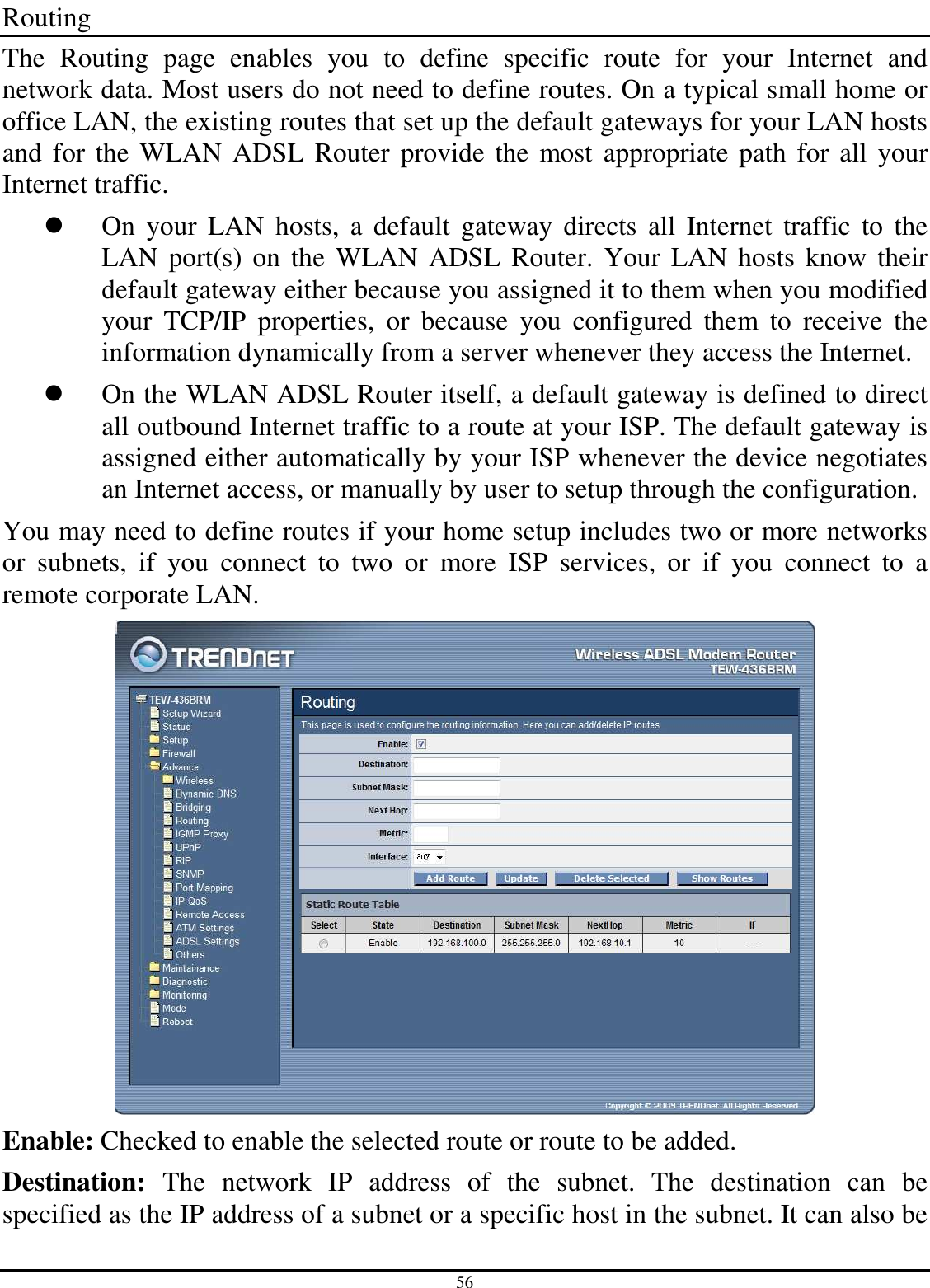
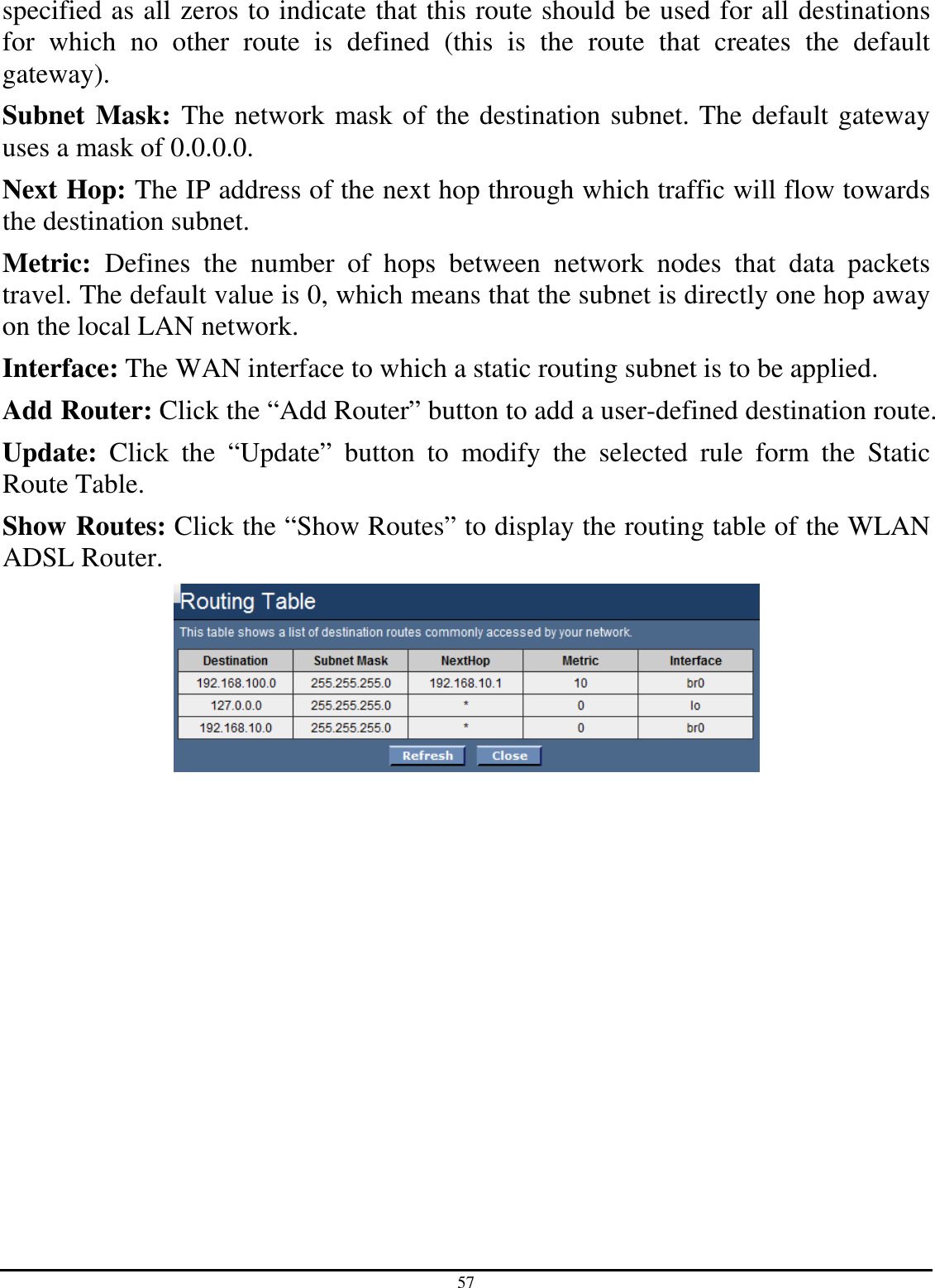
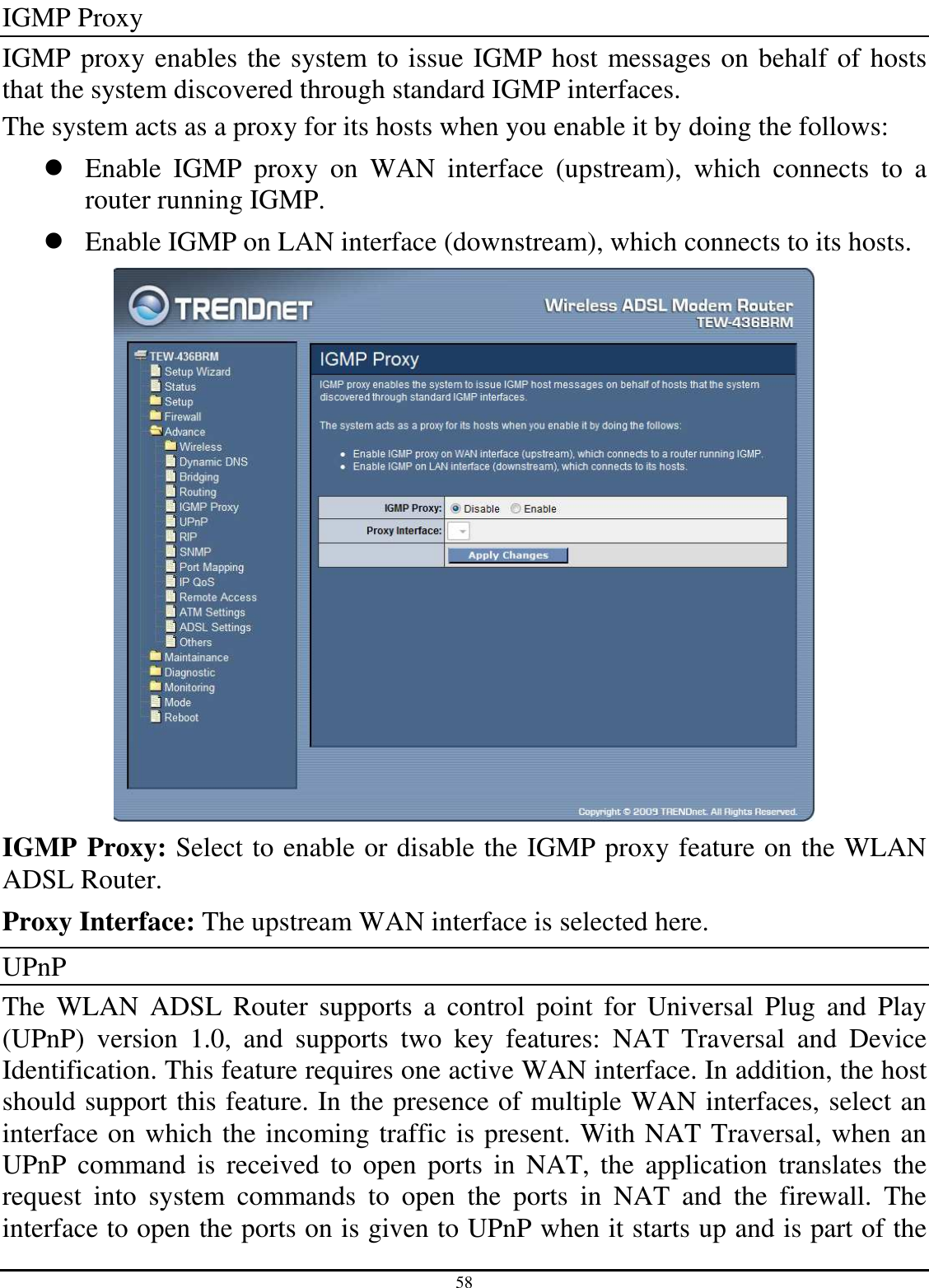
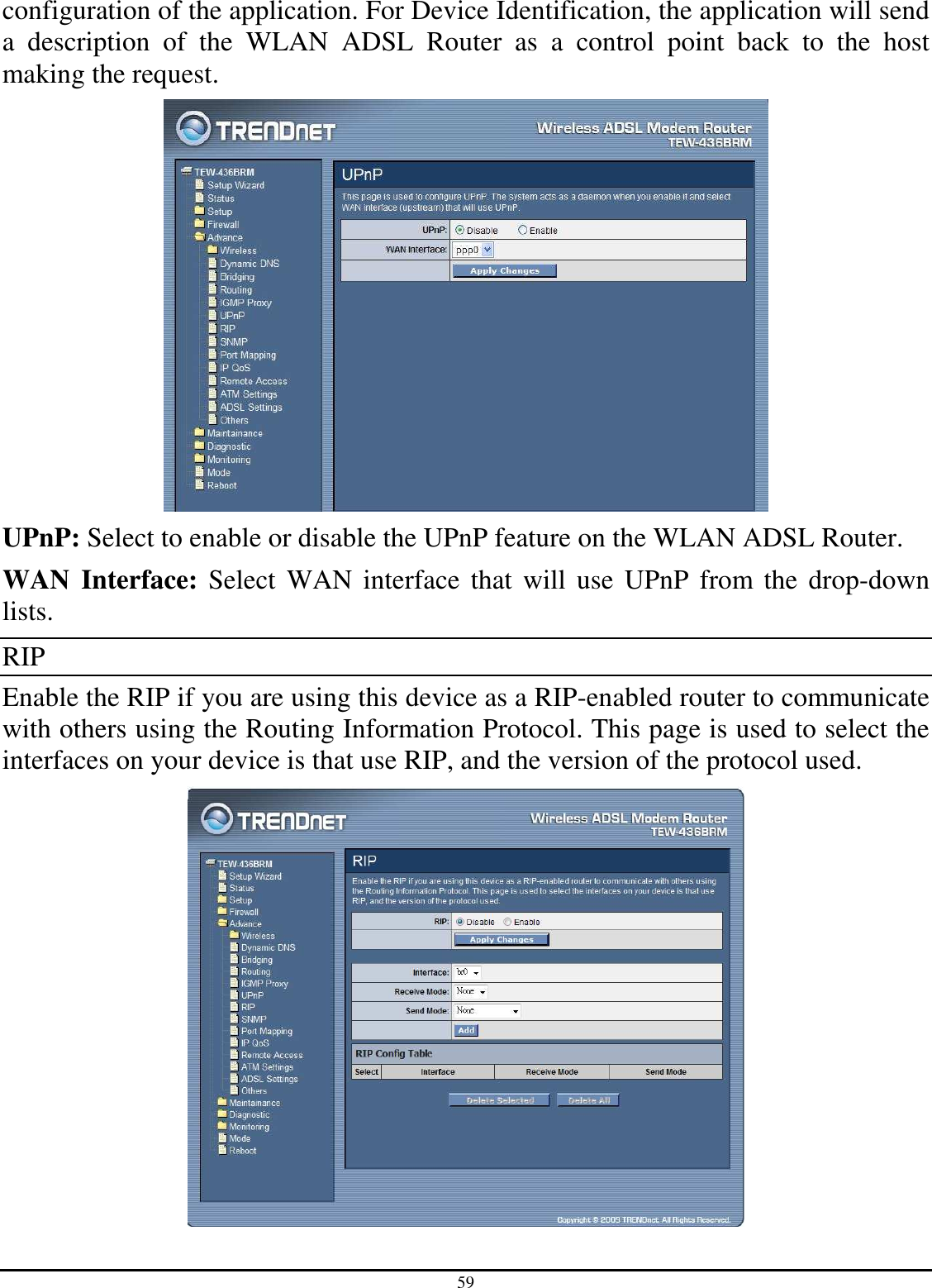
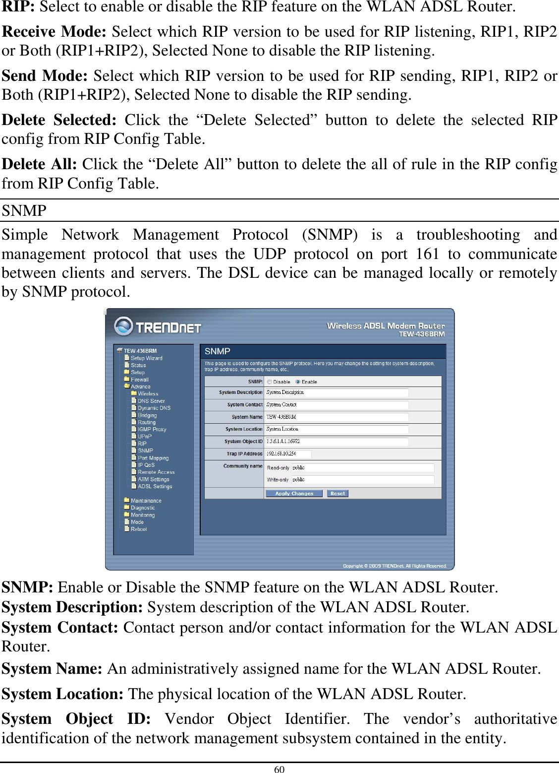
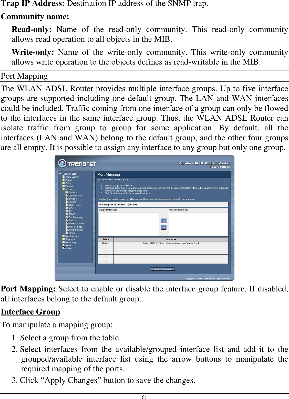
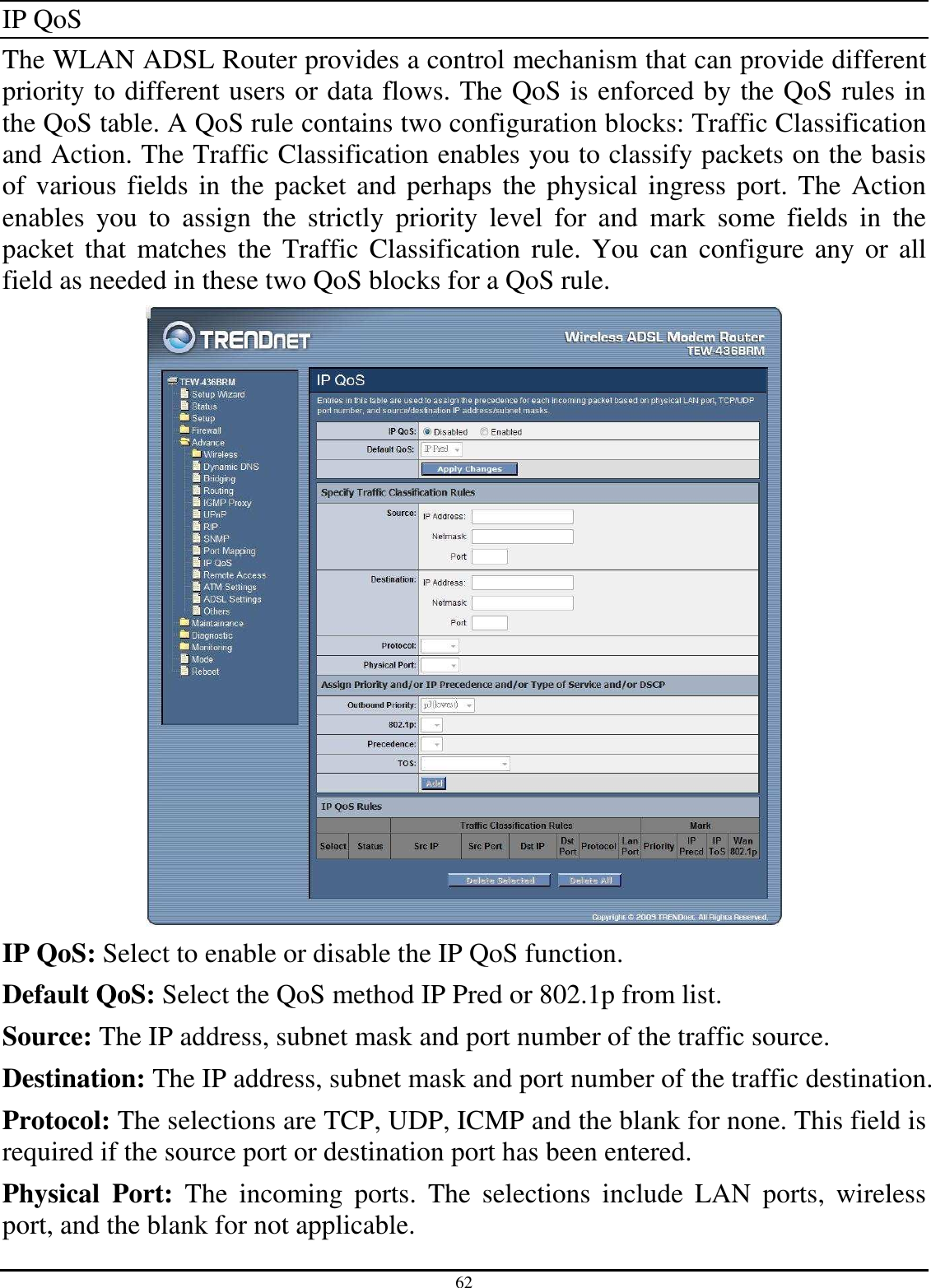
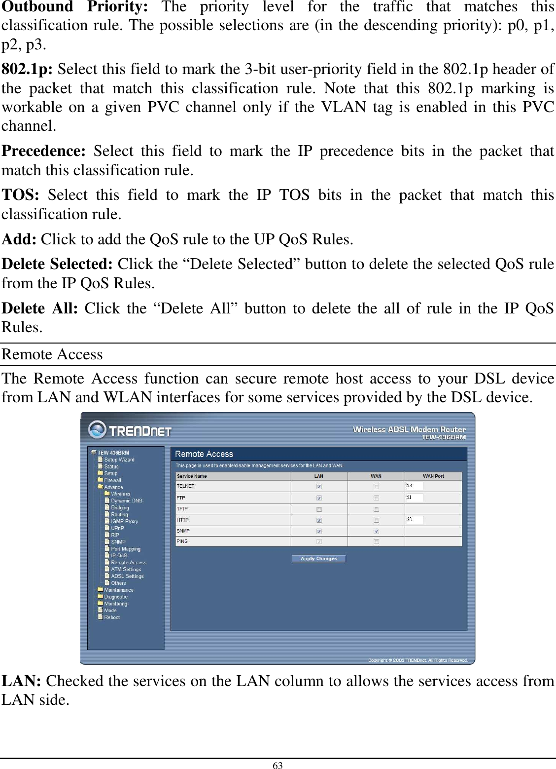
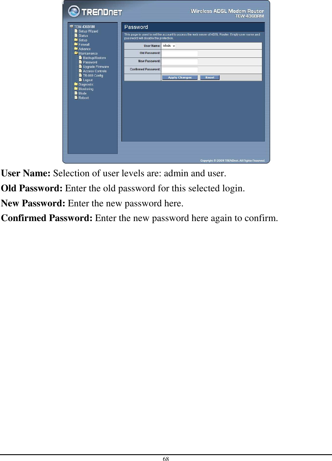
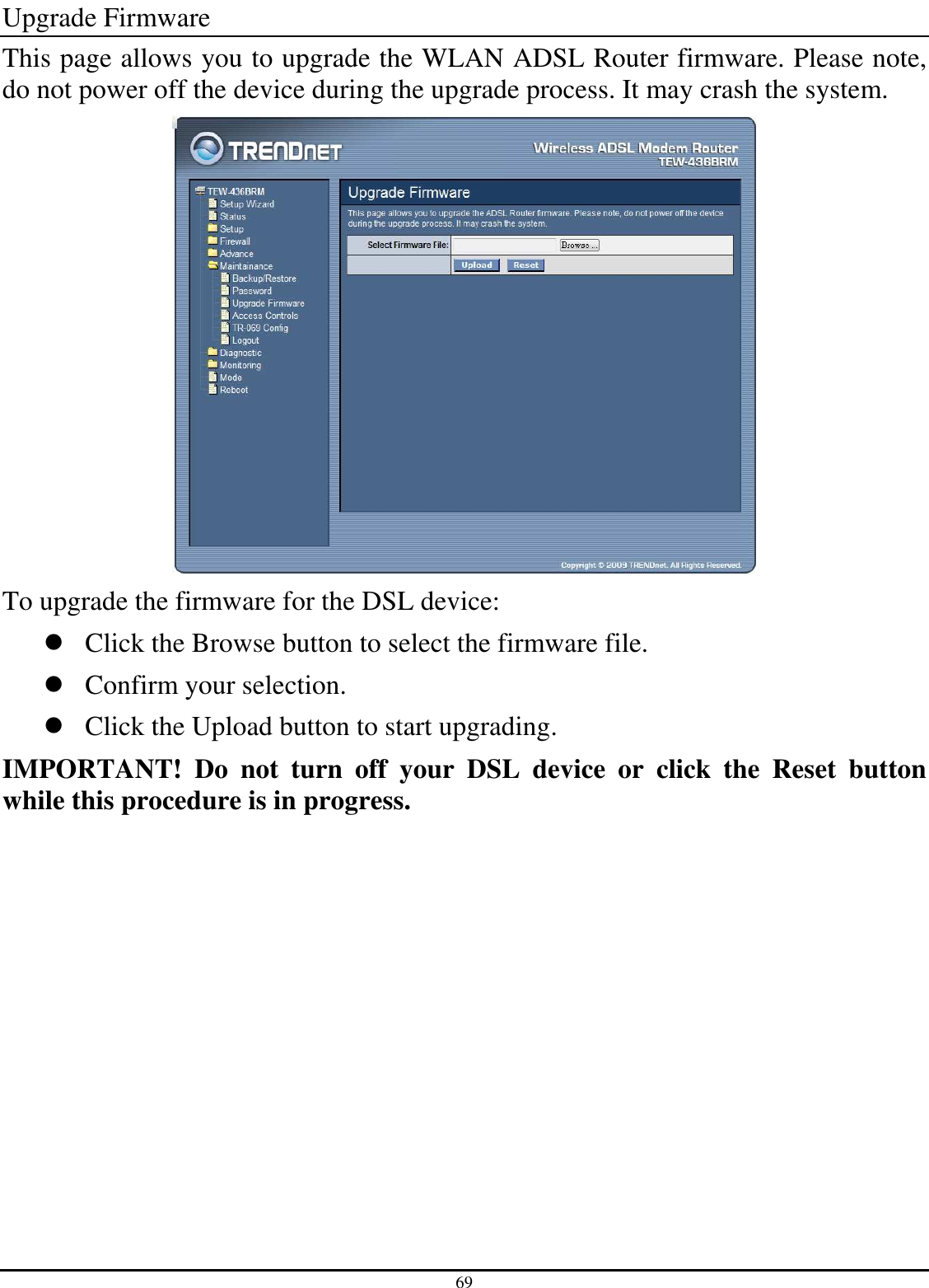
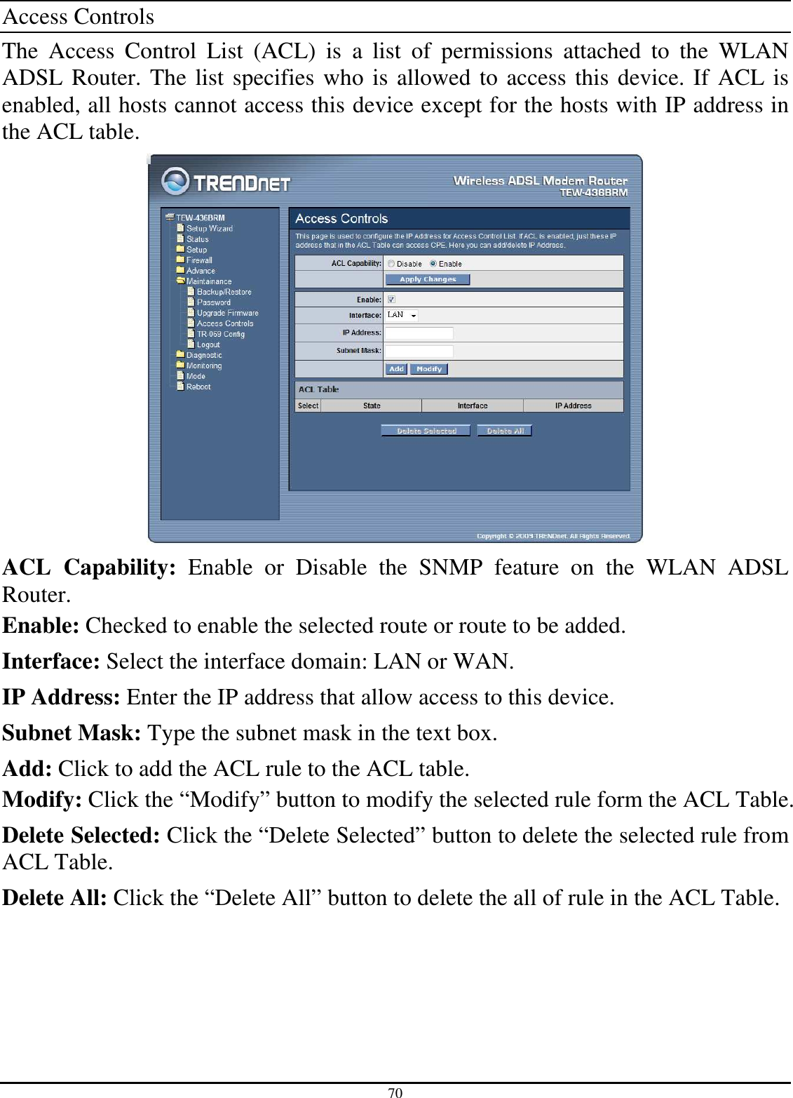
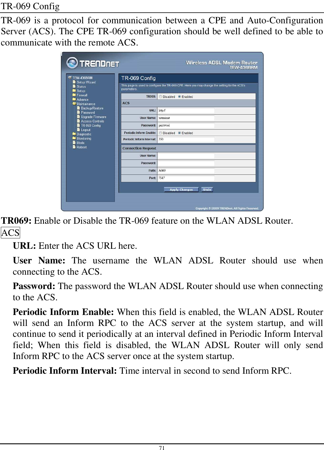
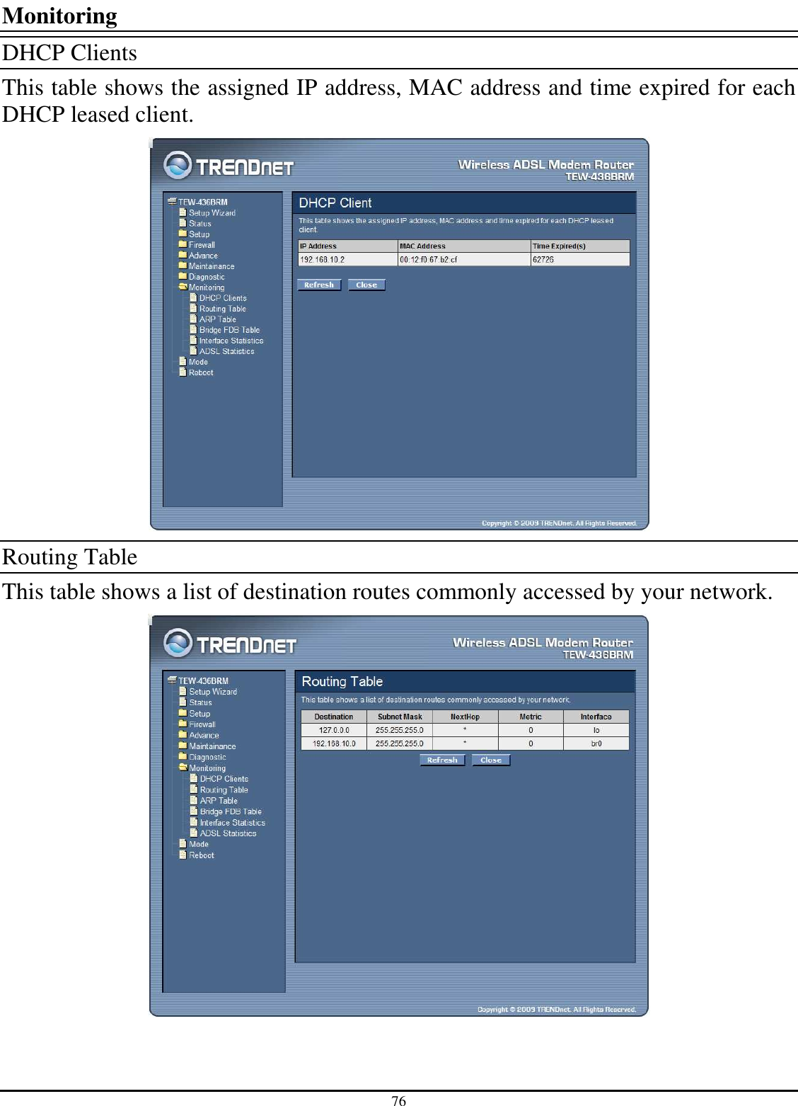
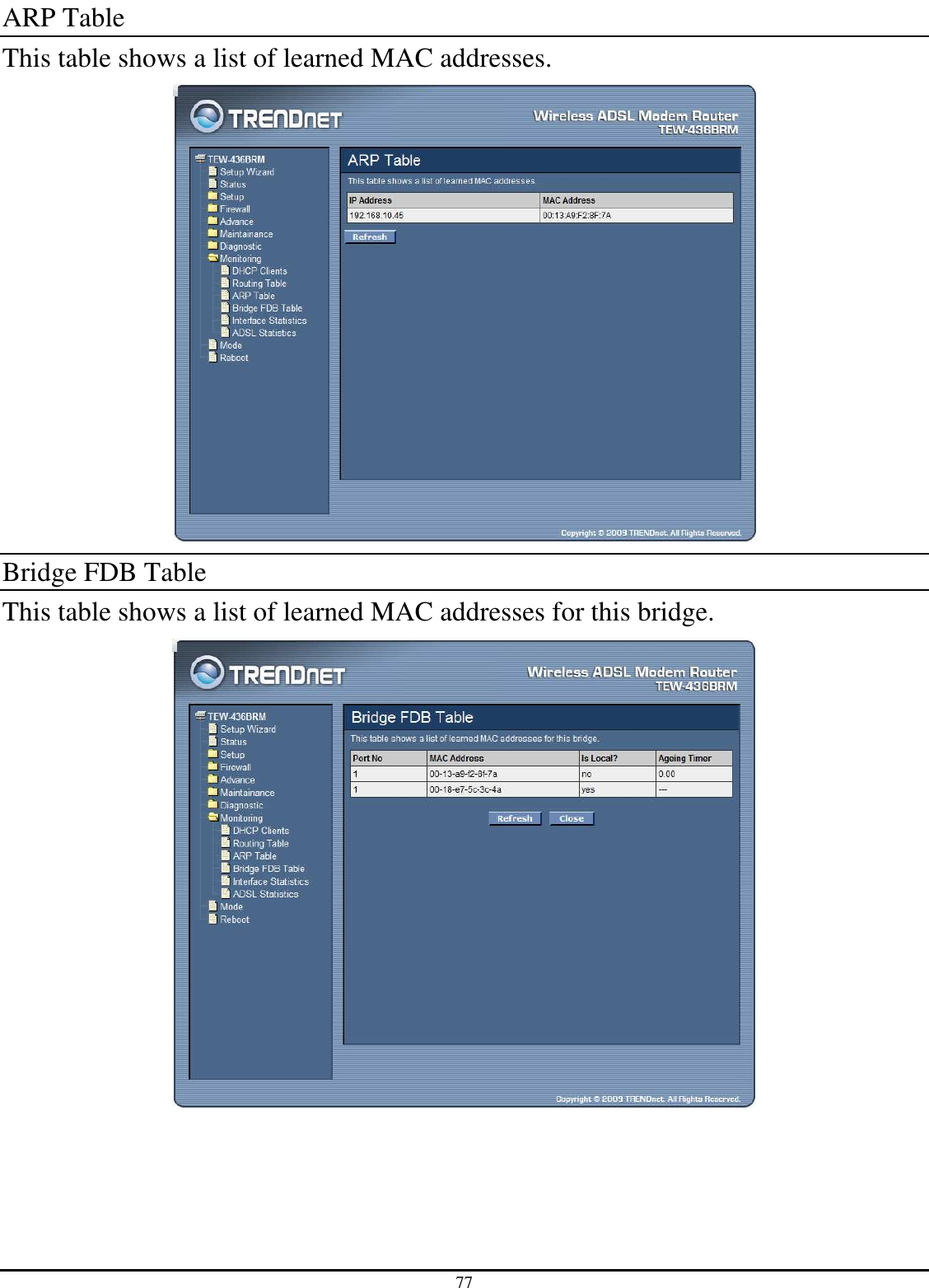
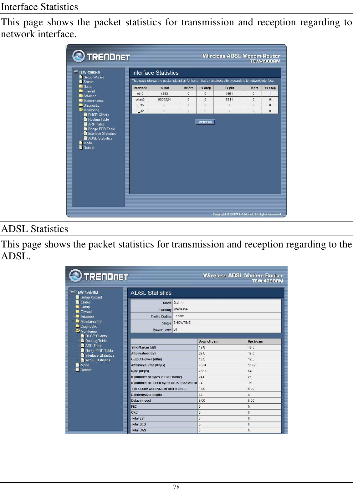
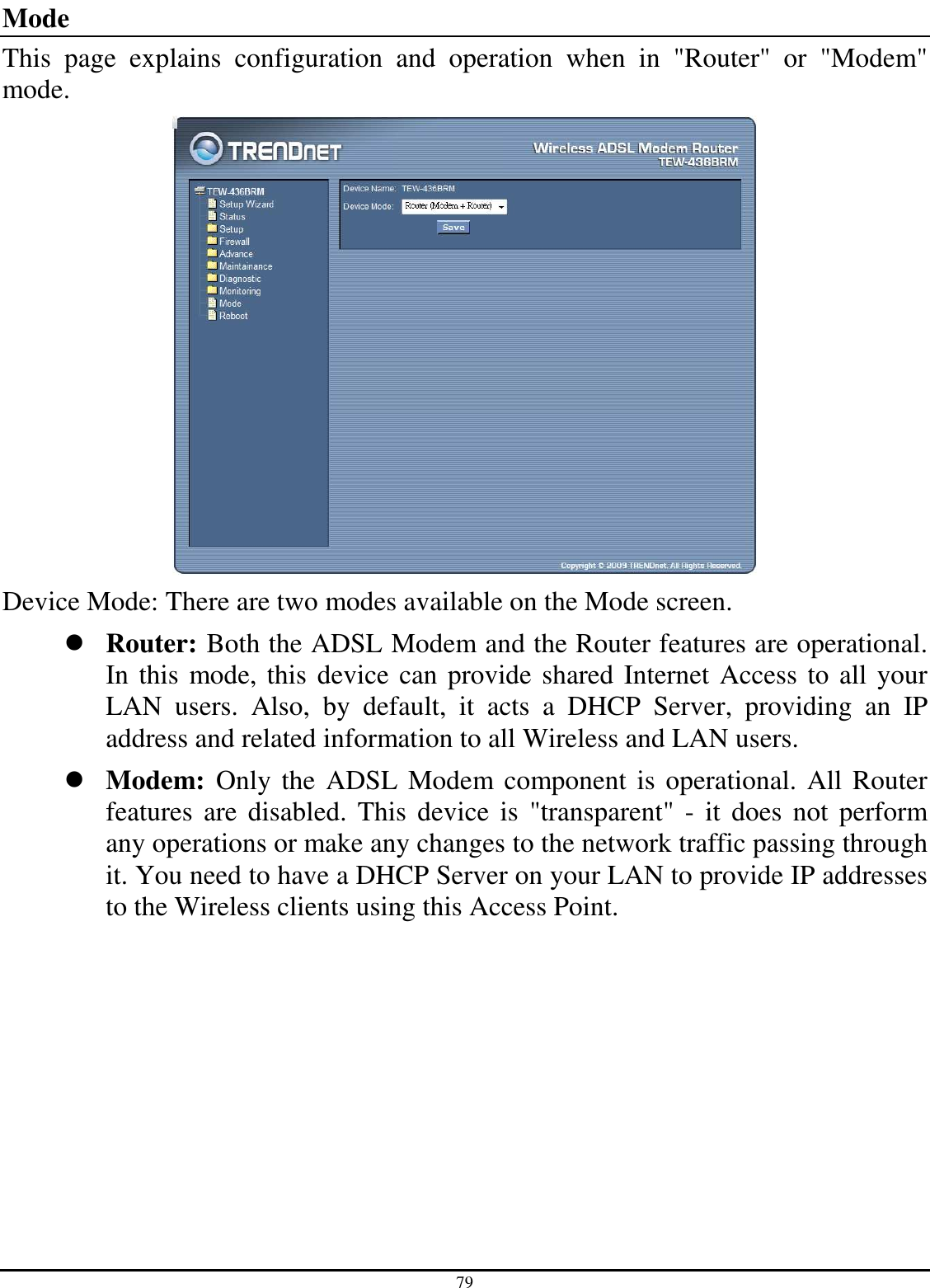
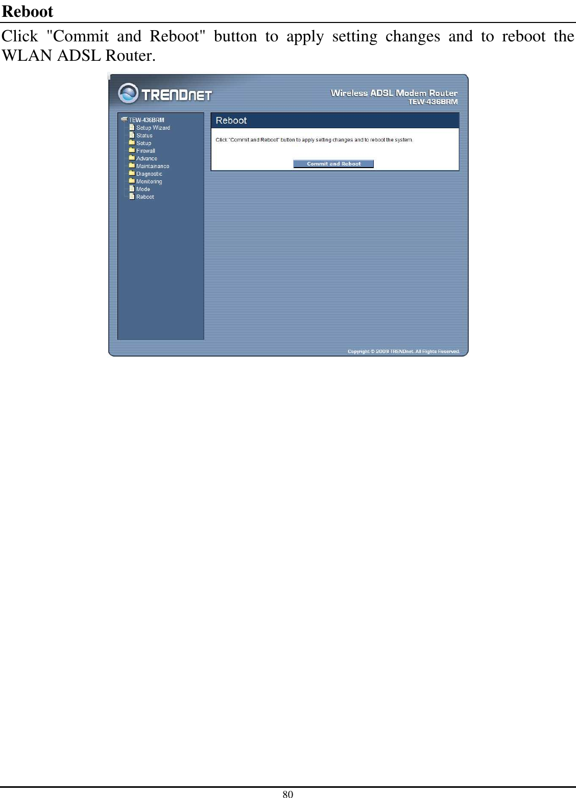
Manual Part 2