TRENDNET TEW455APBOV2 14dBi HIGH POWER WIRELESS OUTDOOR POE ACCESS POINT User Manual
TRENDNET, Inc. 14dBi HIGH POWER WIRELESS OUTDOOR POE ACCESS POINT Users Manual
UserManual.wiki
>
TRENDNET
>
TEW455APBOV2 User Manual
Users Manual
Navigation menu
Upload a User Manual
Namespaces
Wiki Guide
HTML
PDF
Info
Views
User Manual
Discussion / Help
Navigation
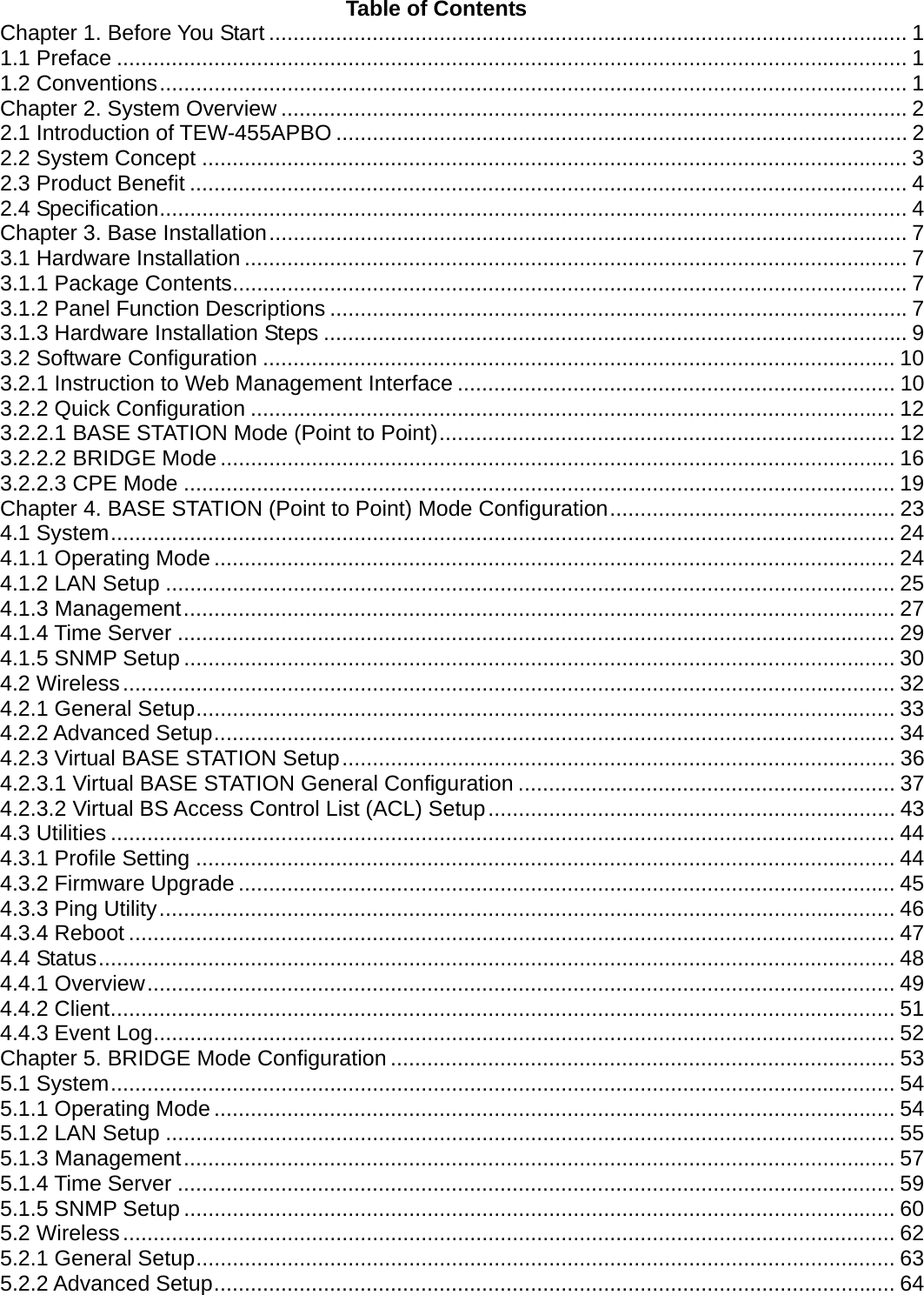
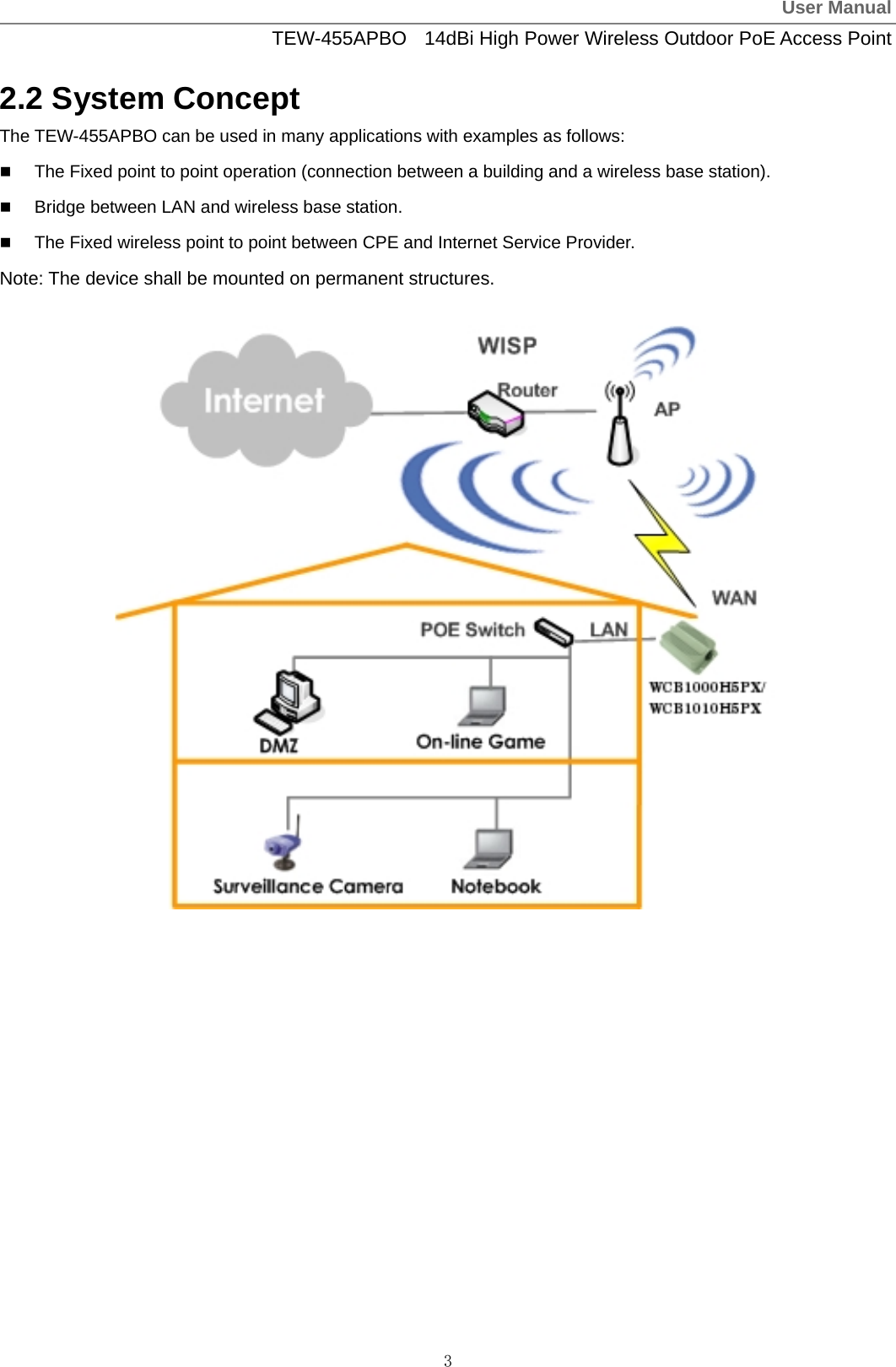
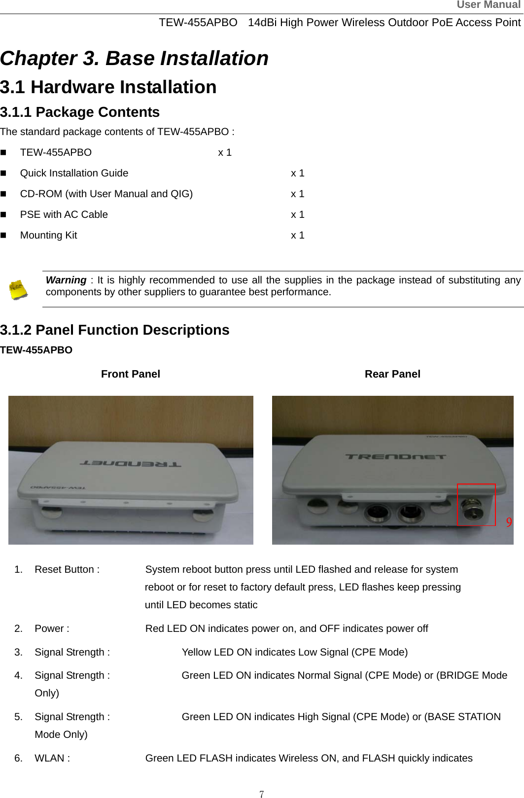
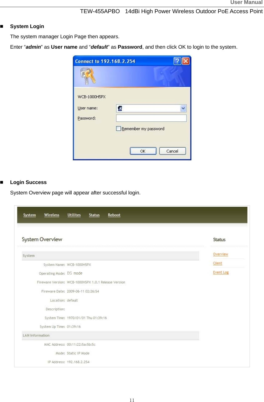
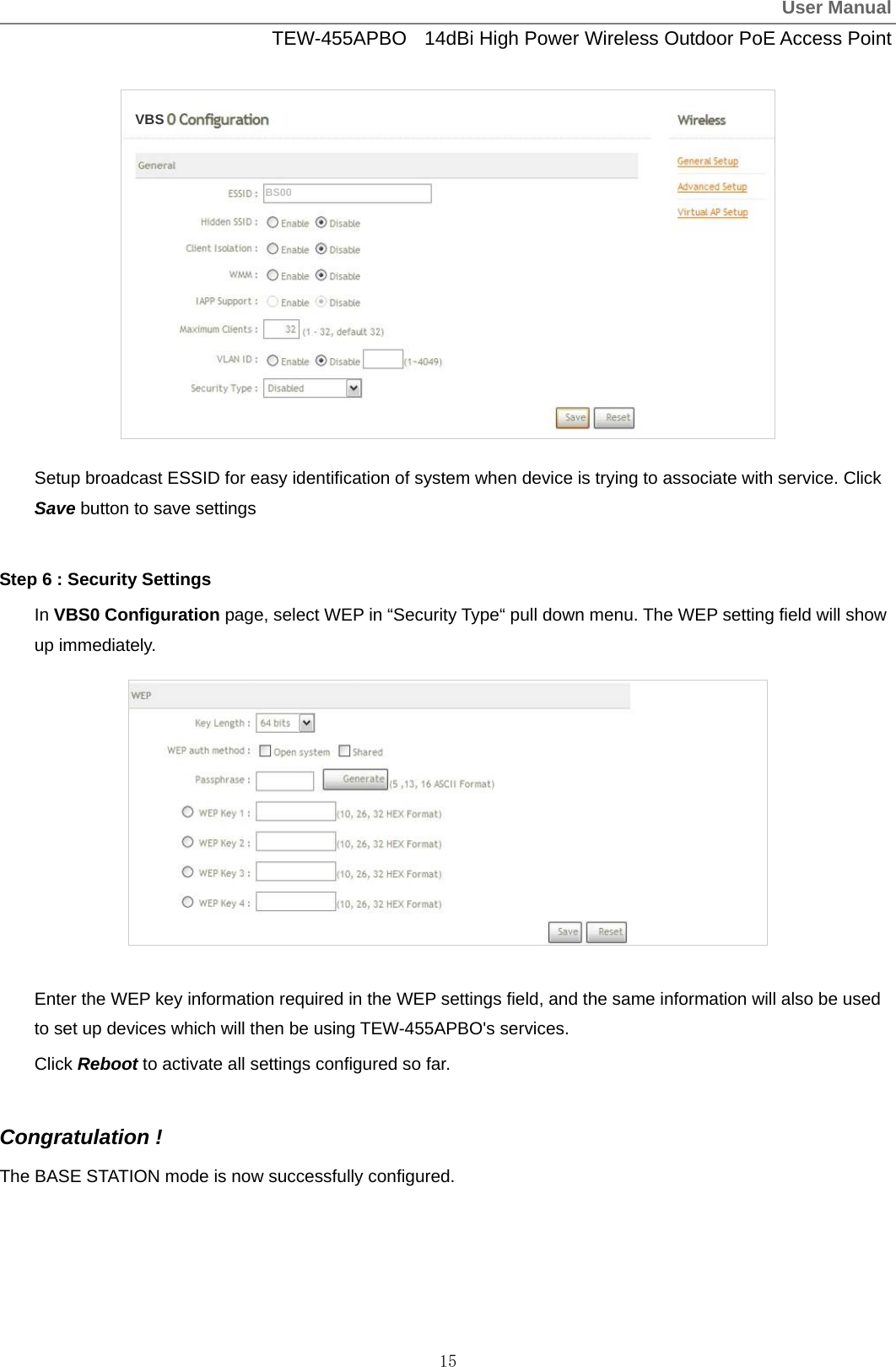
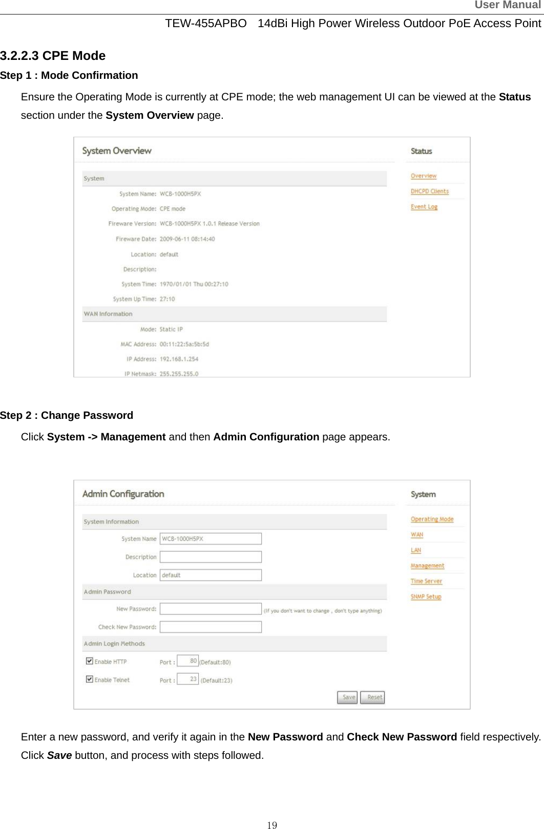
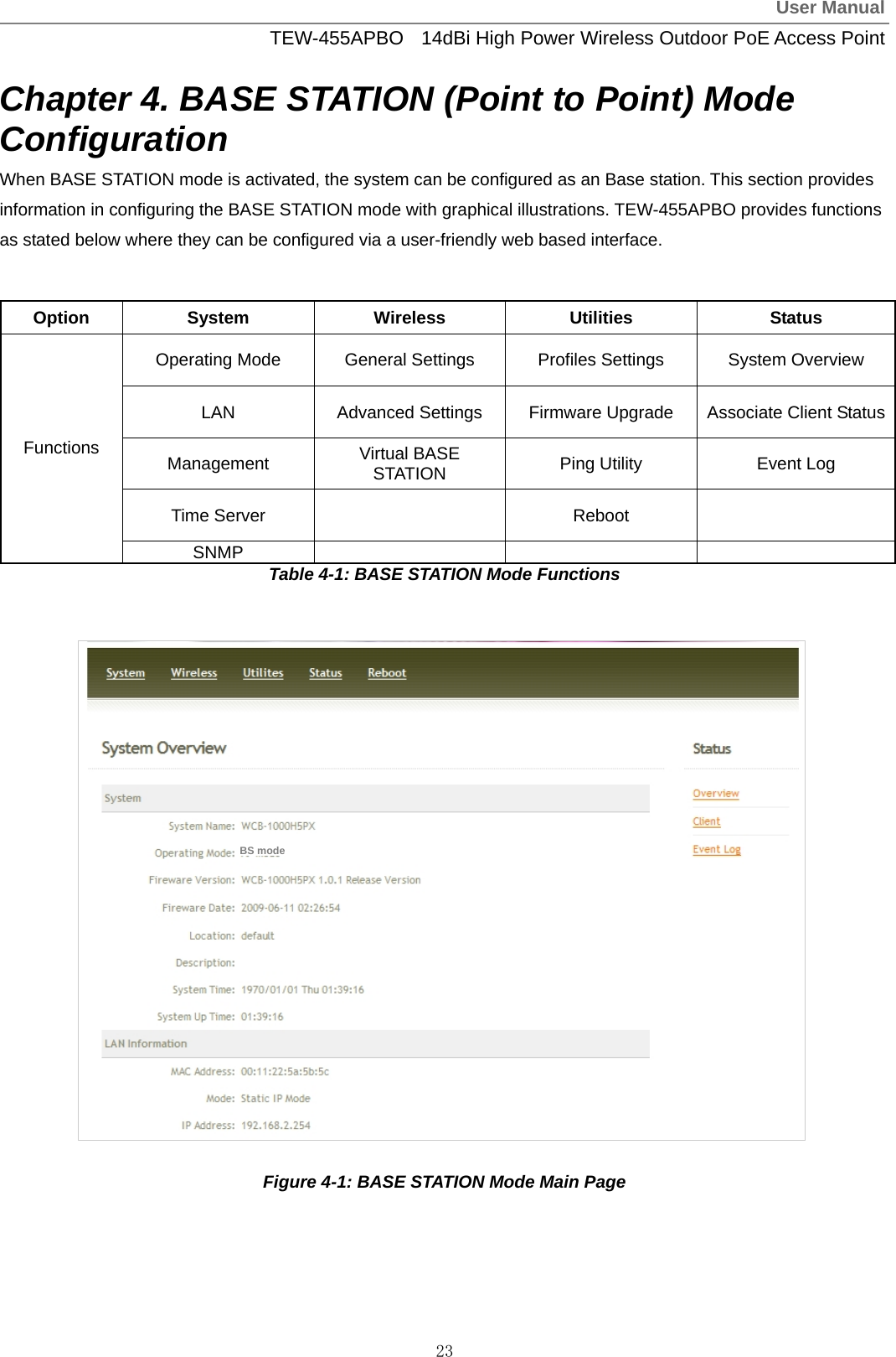


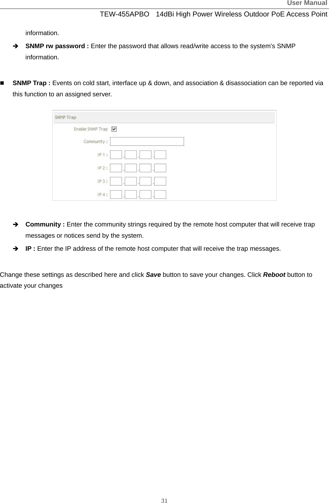
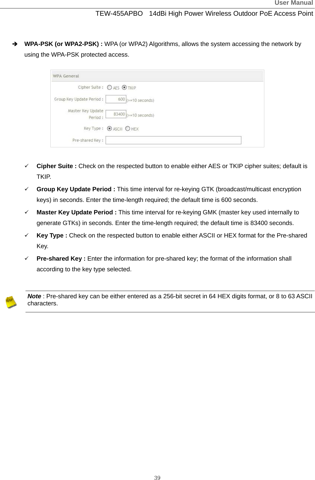

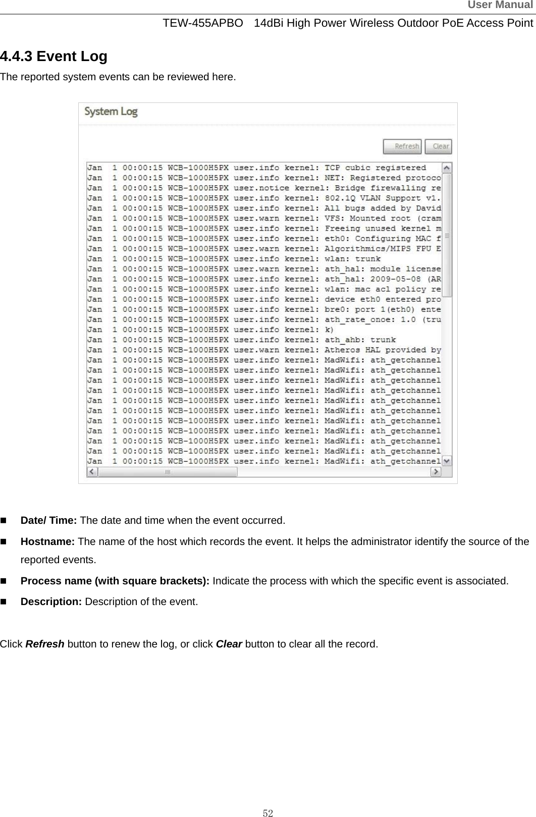
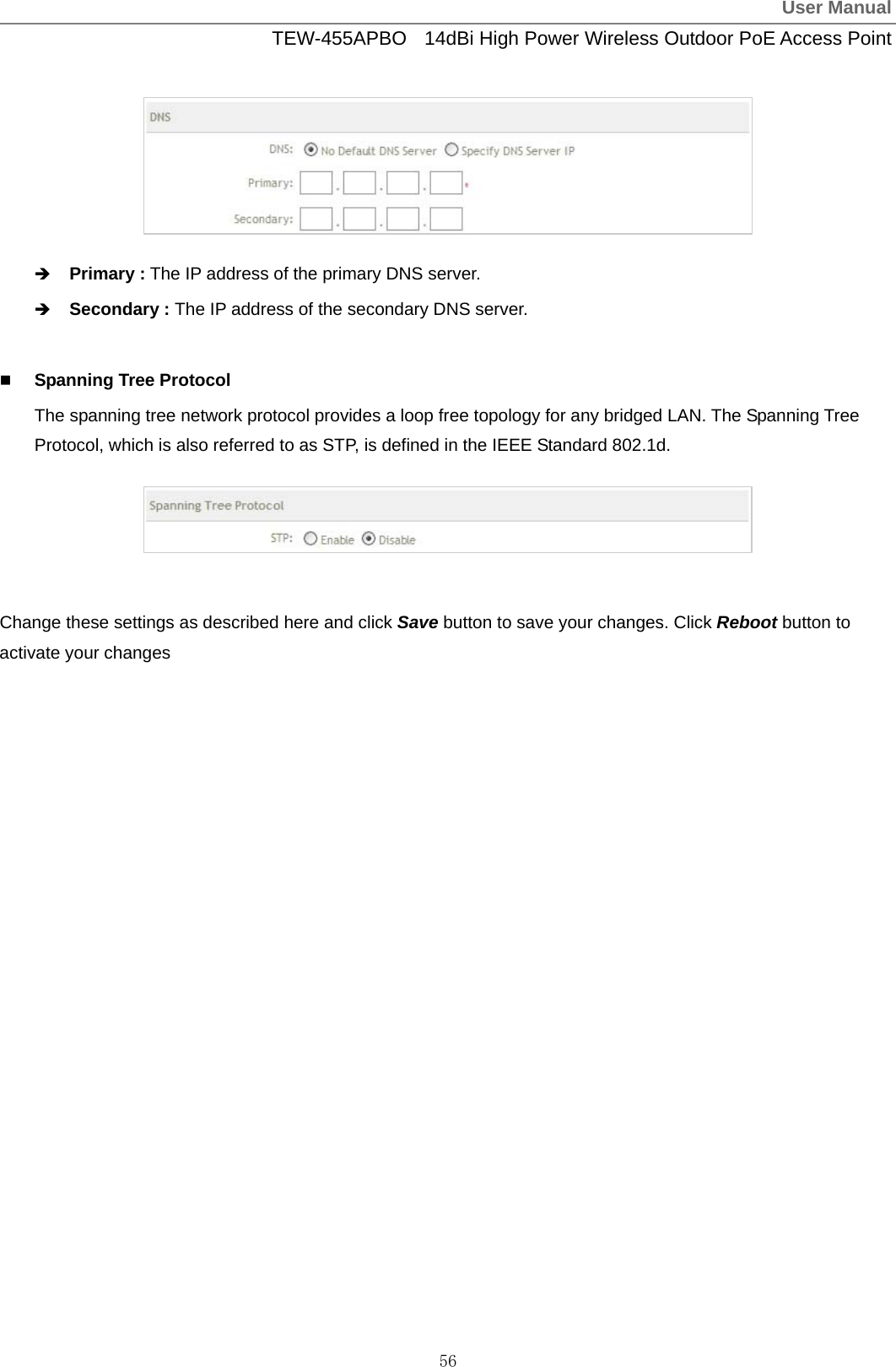


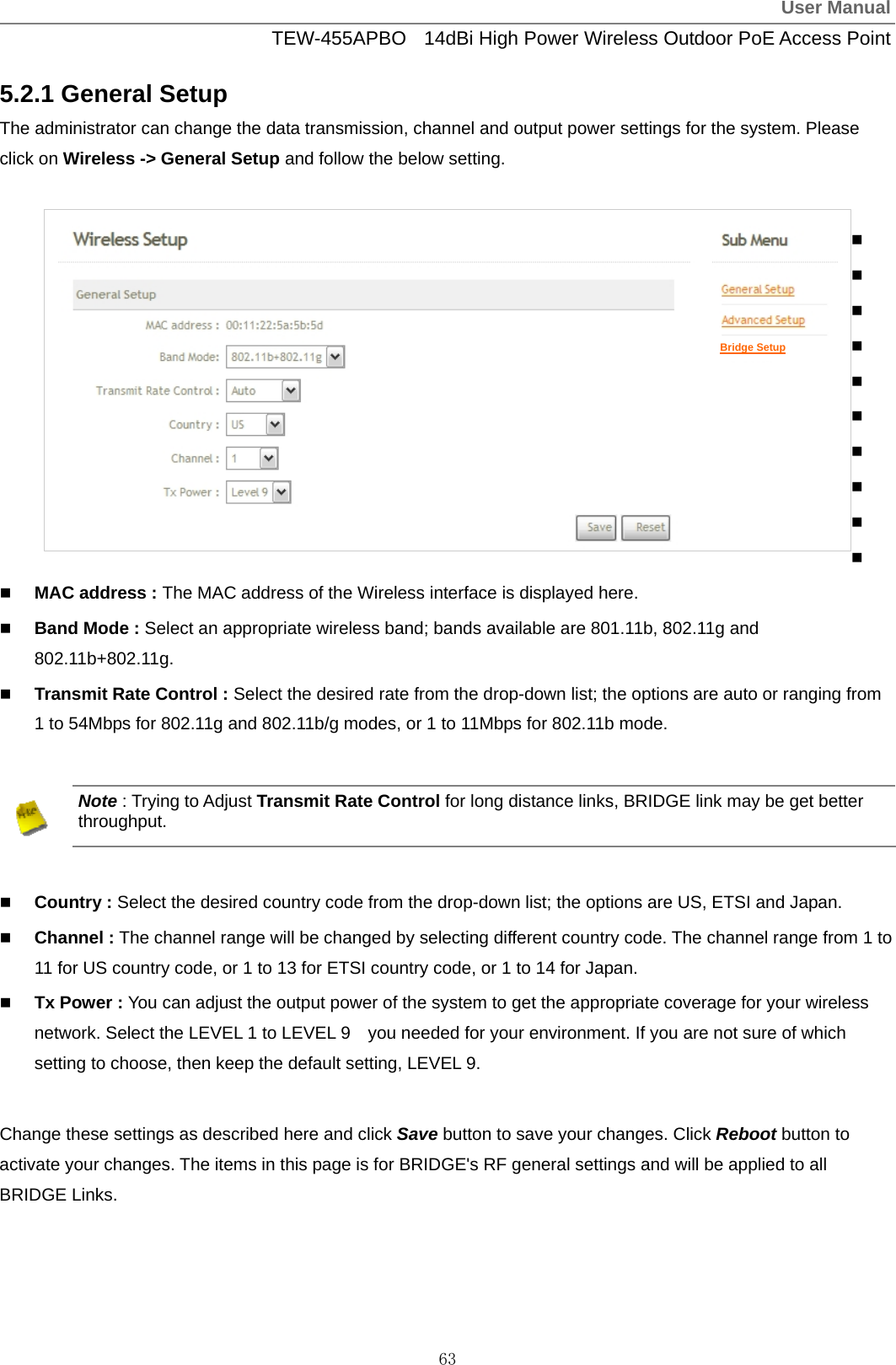


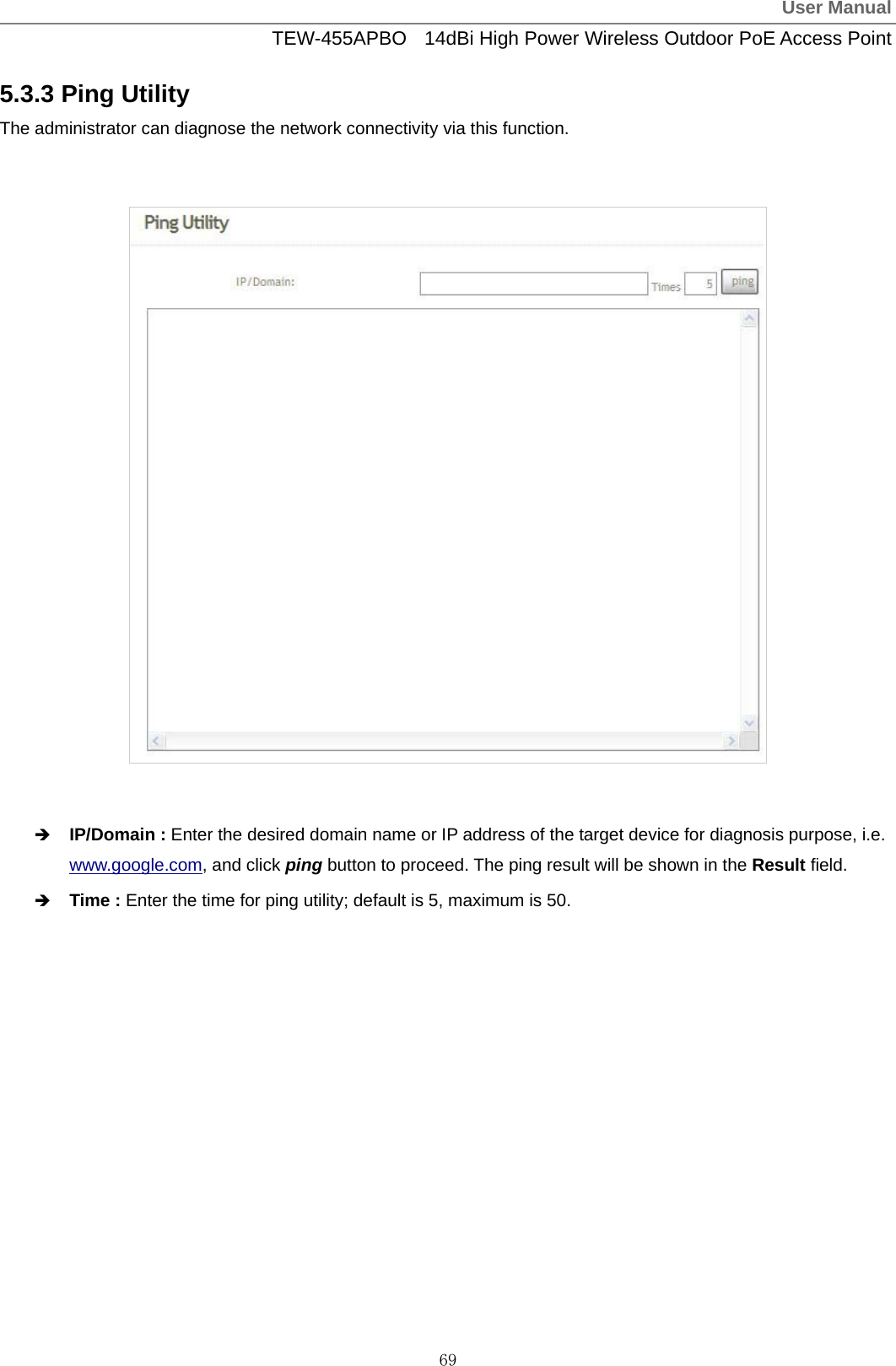

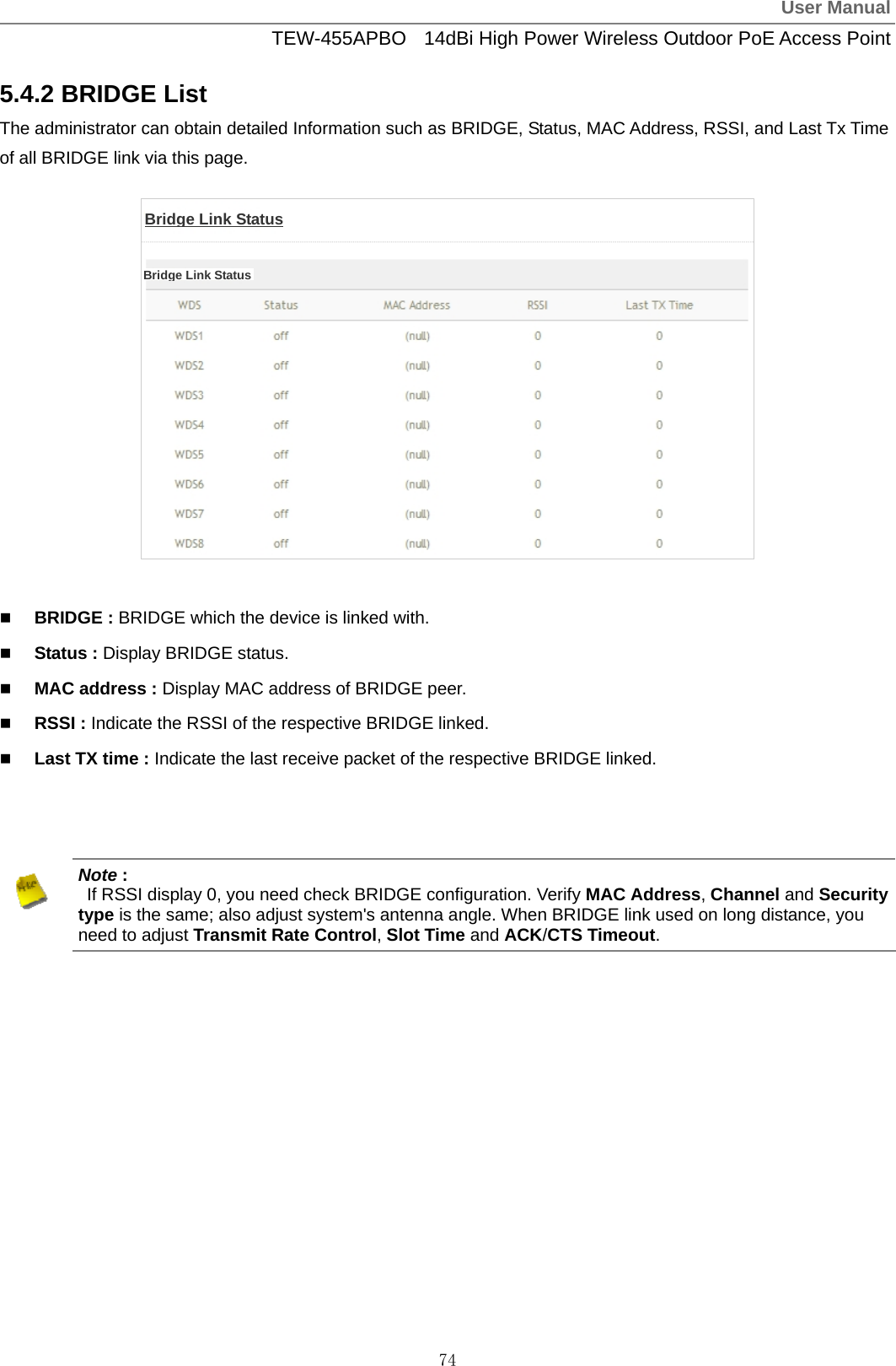

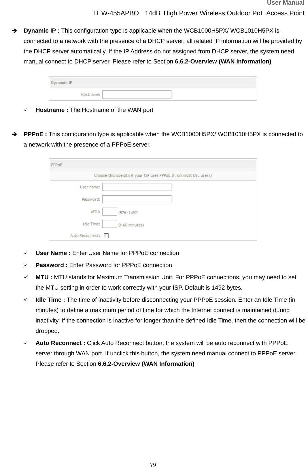
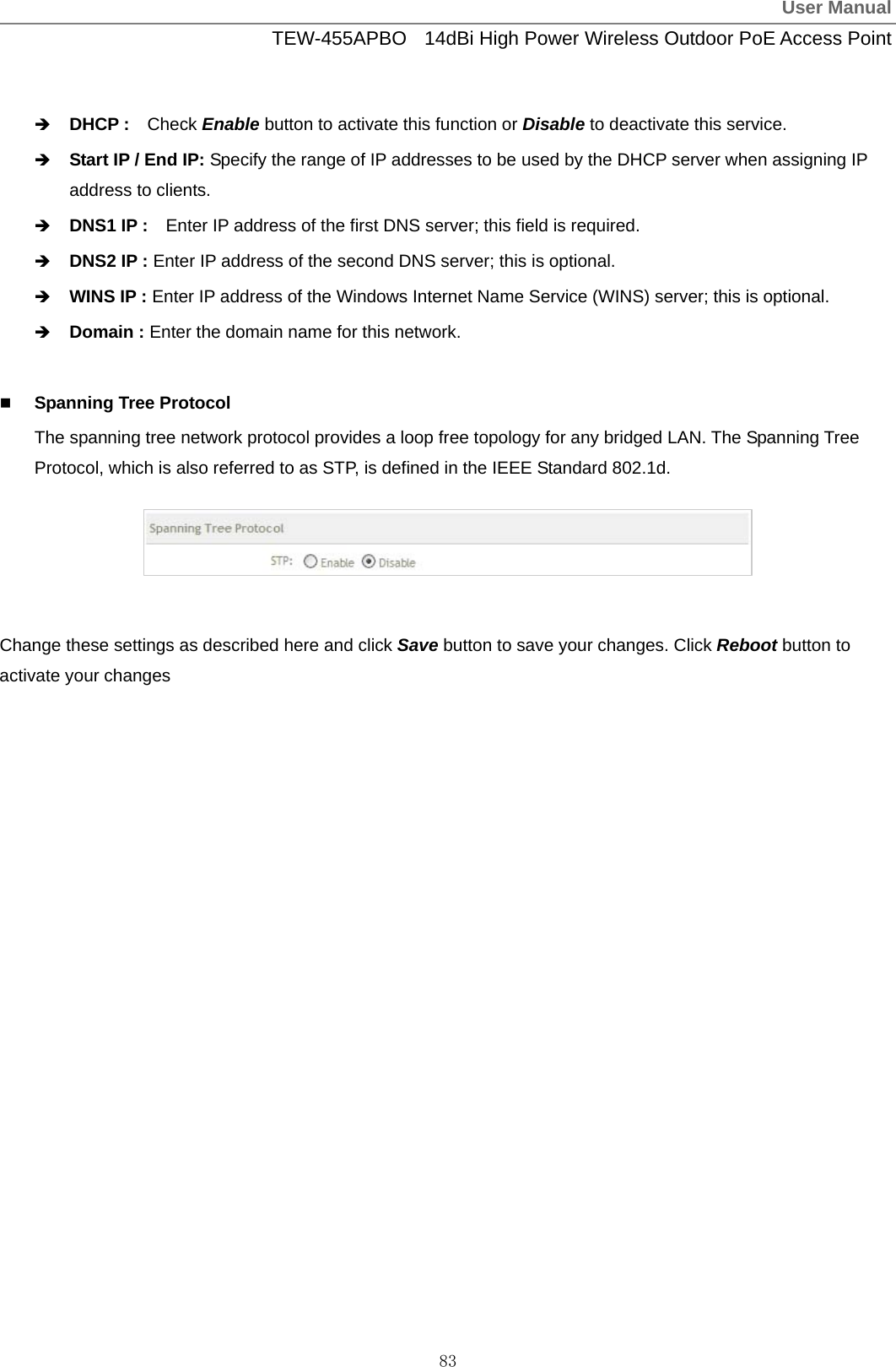
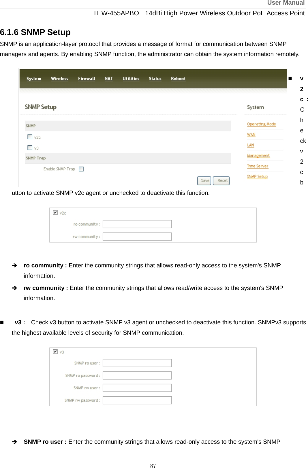
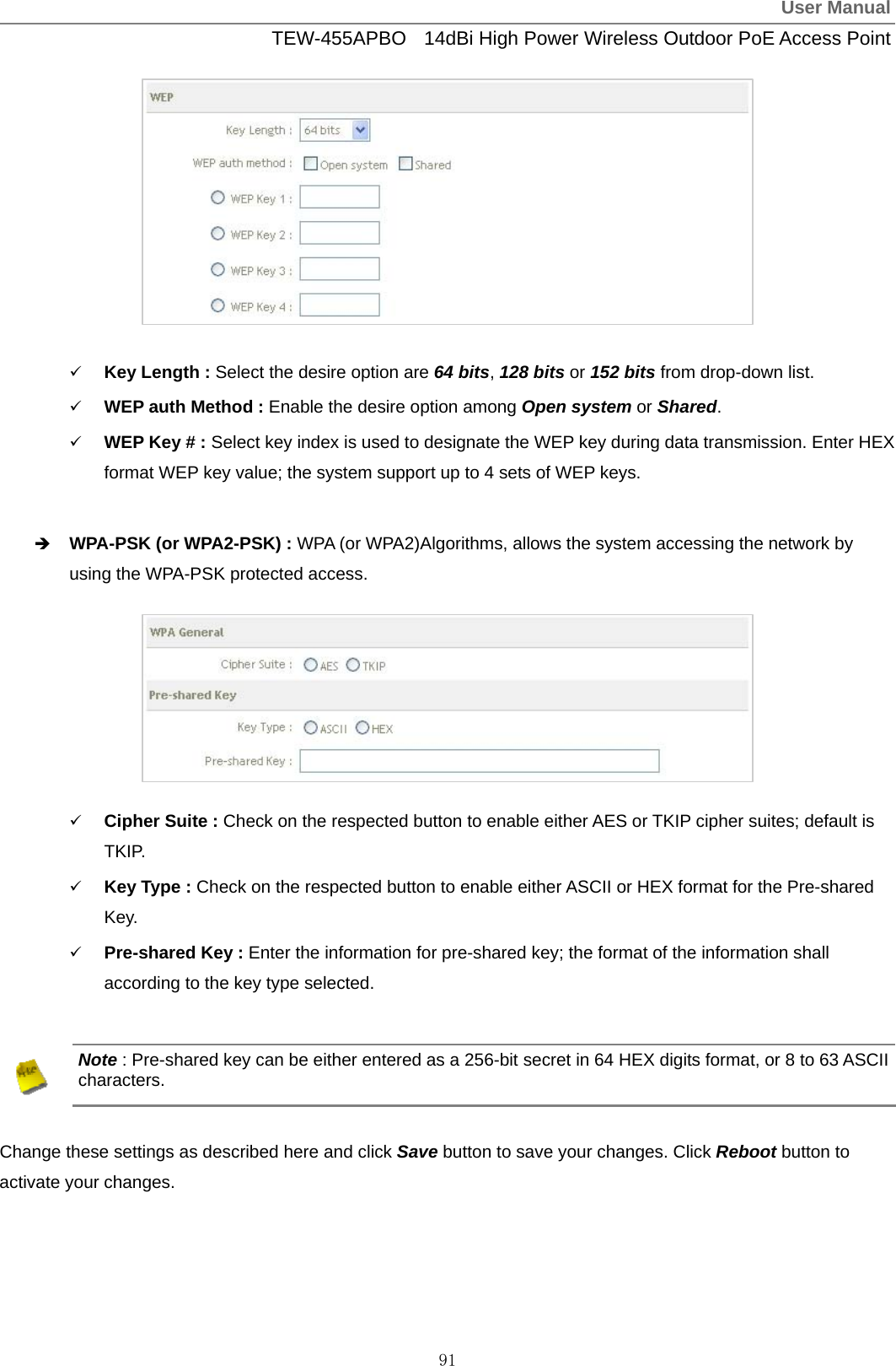
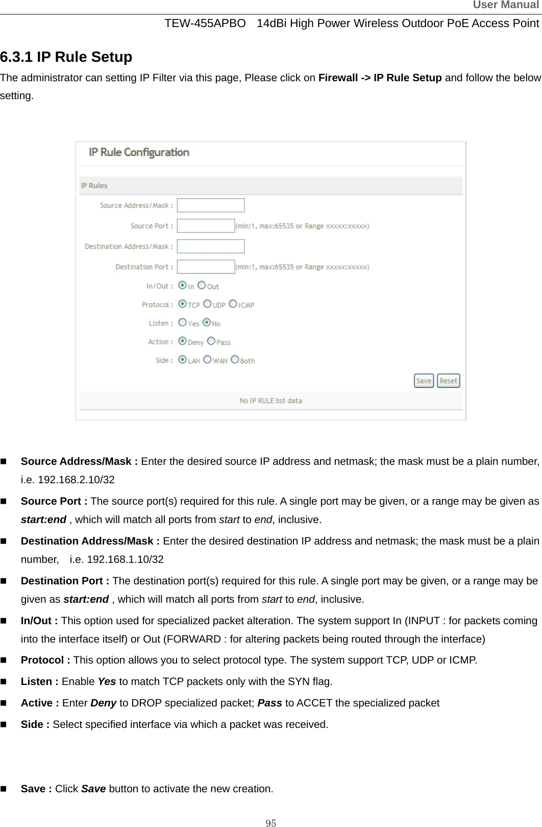
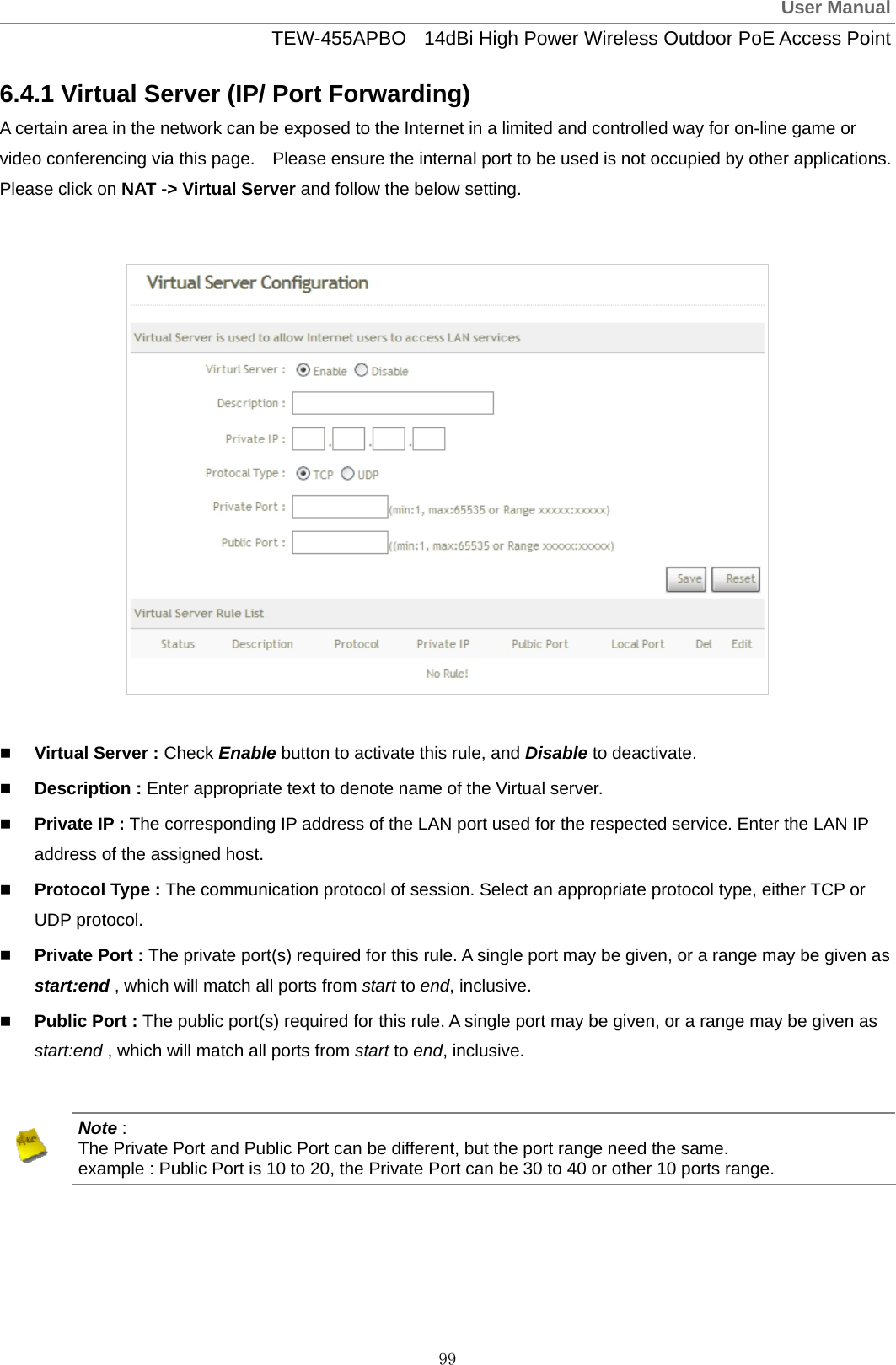


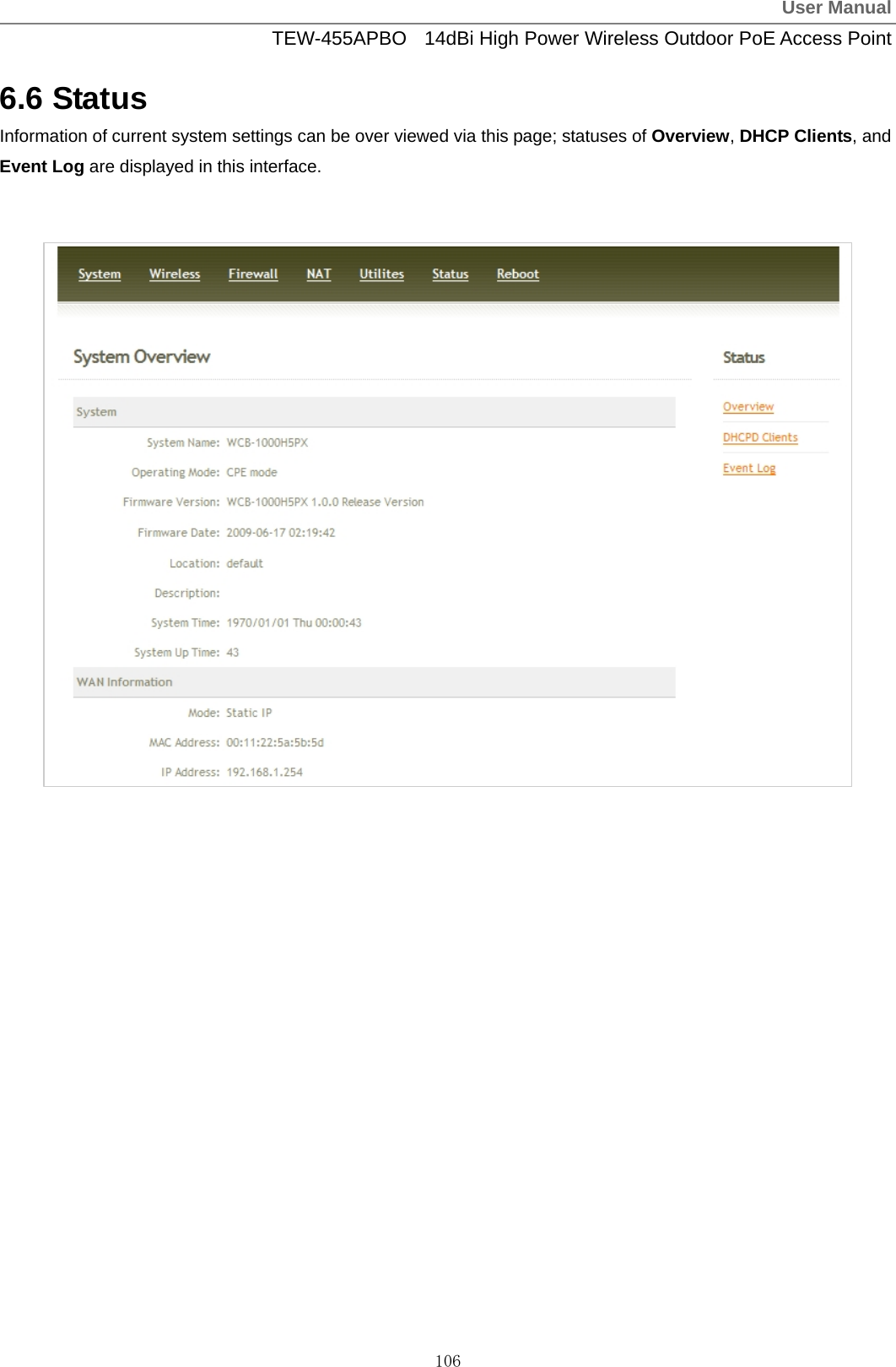
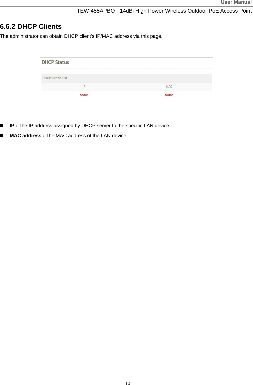

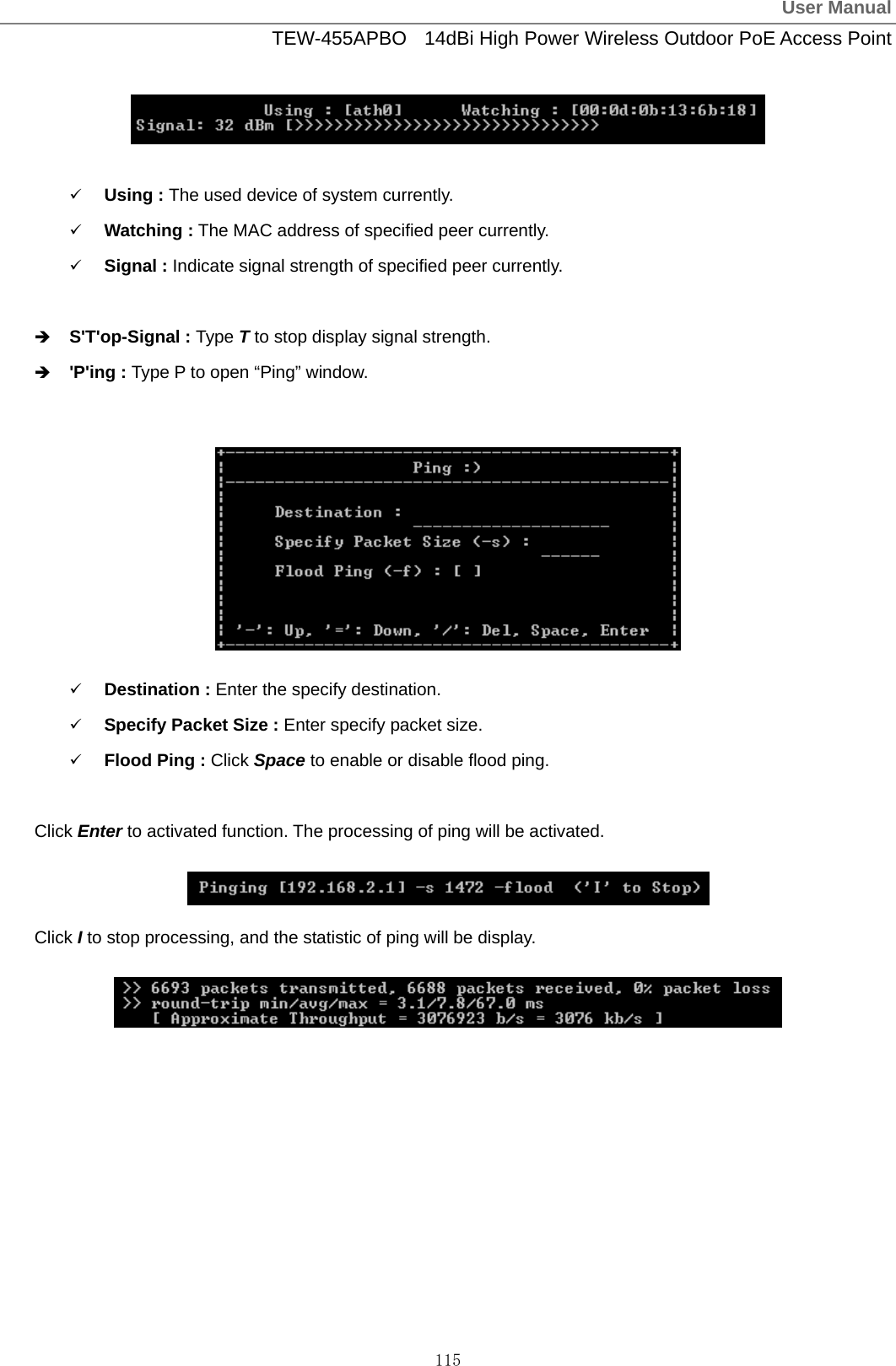
![User ManualTEW-455APBO 14dBi High Power Wireless Outdoor PoE Access Point 118 Appendix B. Valid Characters when using WMI Table C Valid Characters for using WMI Block Field Valid Characters IP Address IP Format; 1-254 IP Netmask 128.0.0.0 ~ 255.255.255.252 IP Gateway IP Format; 1-254 Primary IP Format; 1-254 Secondary IP Format; 1-254 LAN Hostname Length : 32 0-9, A-Z, a-z @ - _ . Manual MAC Address 12 HEX chars IP Address IP Format; 1-254 IP Netmask 128.0.0.0 ~ 255.255.255.252 IP Gateway IP Format; 1-254 Hostname Length : 32 0-9, A-Z, a-z @ - _ . User name Length : 32 0-9, A-Z, a-z ~ ! @ # $ % ^ * ( ) _ + - { } | : < > ? [ ] / ; ` , . = Password Length : 32 0-9, A-Z, a-z ~ ! @ # $ % ^ * ( ) _ + - { } | : < > ? [ ] / ; ` , . = MTU 576 ~ 1492 Idle Time 0 ~ 60 minutes Primary IP Format; 1-254 WAN Secondary IP Format; 1-254 Start IP IP Format; 1-254 End IP IP Format; 1-254 DNS1 IP IP Format; 1-254 DNS2 IP IP Format; 1-254 WINS IP IP Format; 1-254 DHCP Server Domain Length : 32 0-9, A-Z, a-z ~ ! @ # $ % ^ * ( ) _ + - { } | : < > ? [ ] / ; ` , . =](https://usermanual.wiki/TRENDNET/TEW455APBOV2/User-Guide-1253836-Page-121.png)
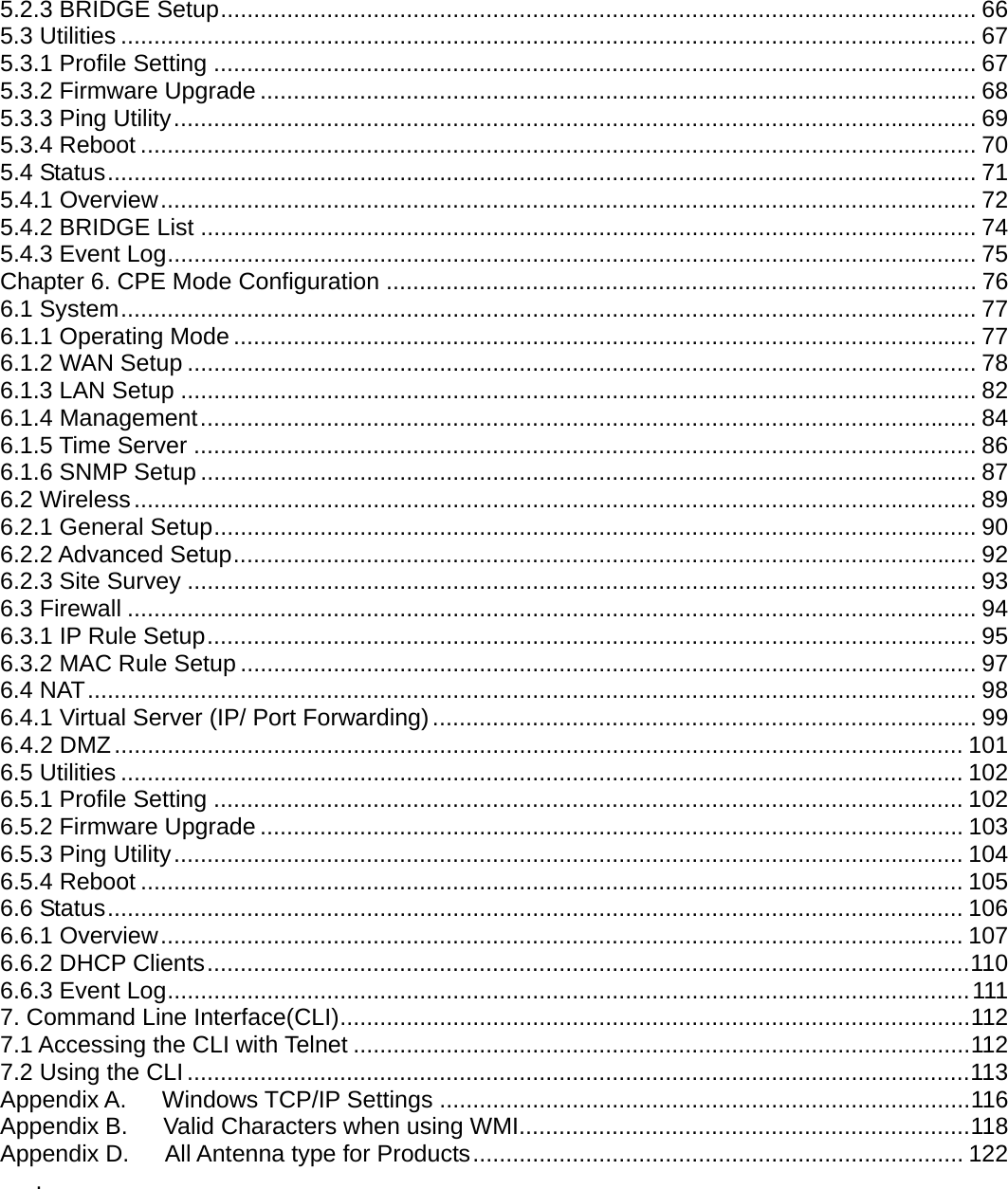
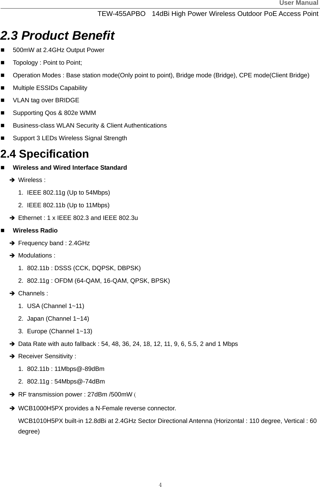
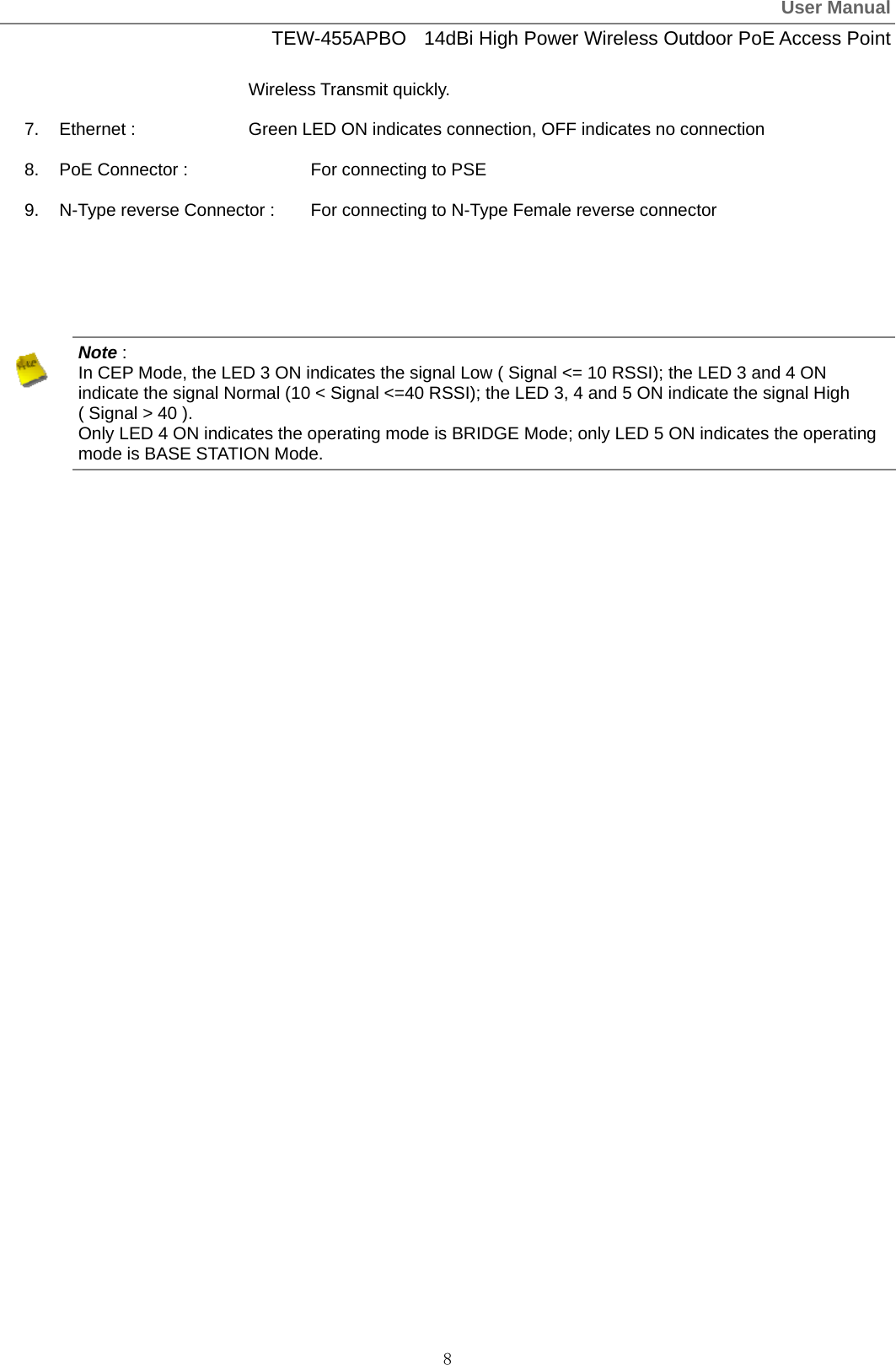
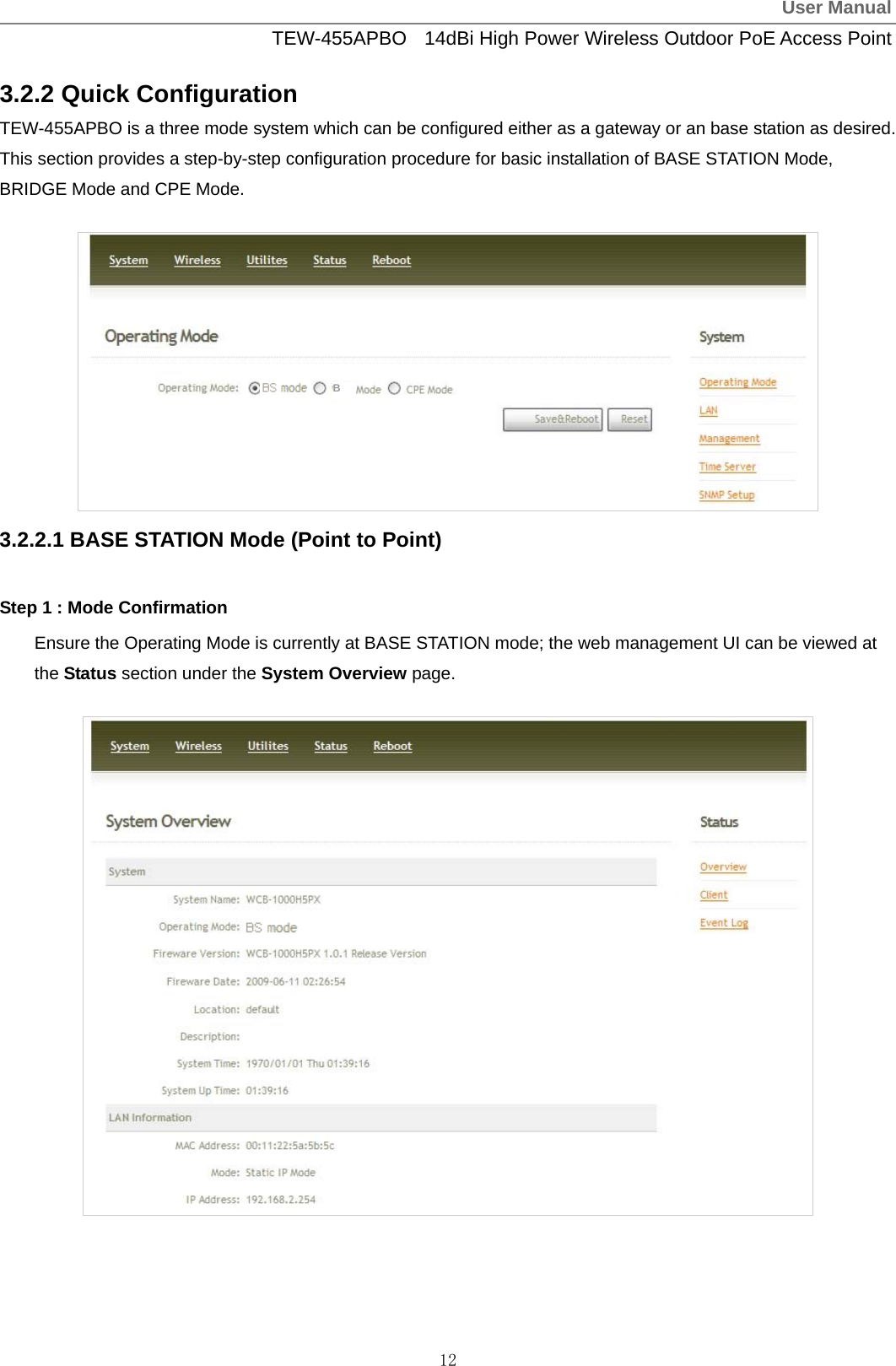
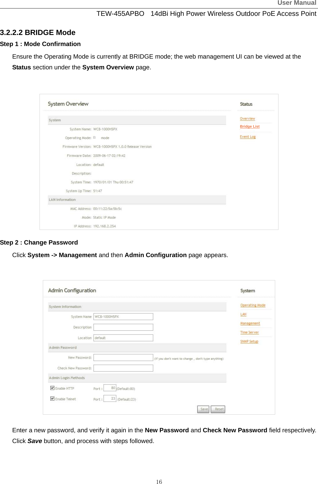
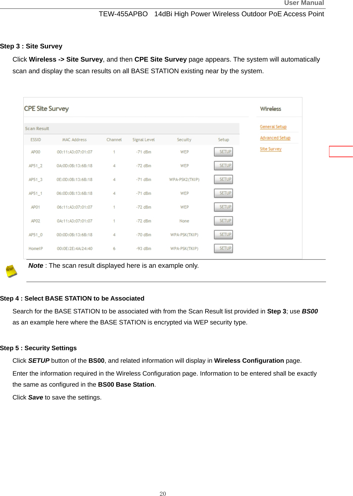
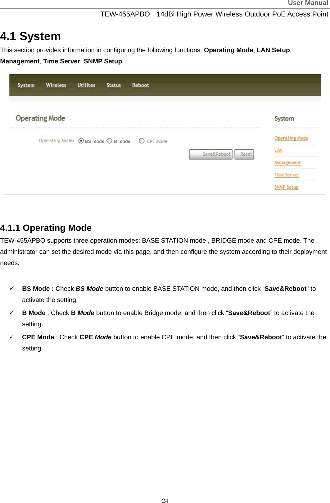
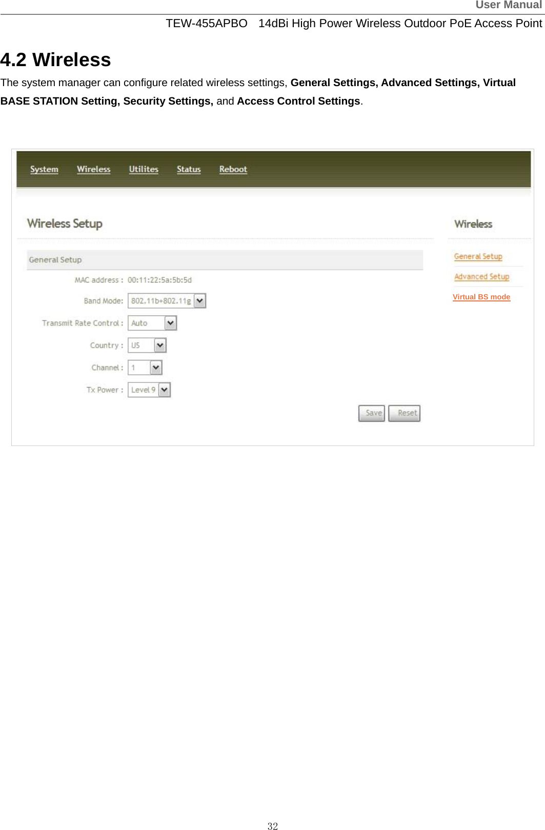
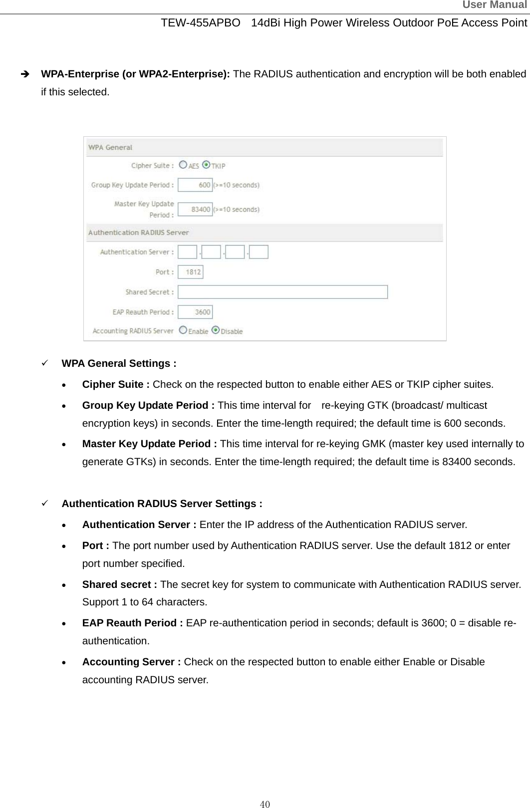
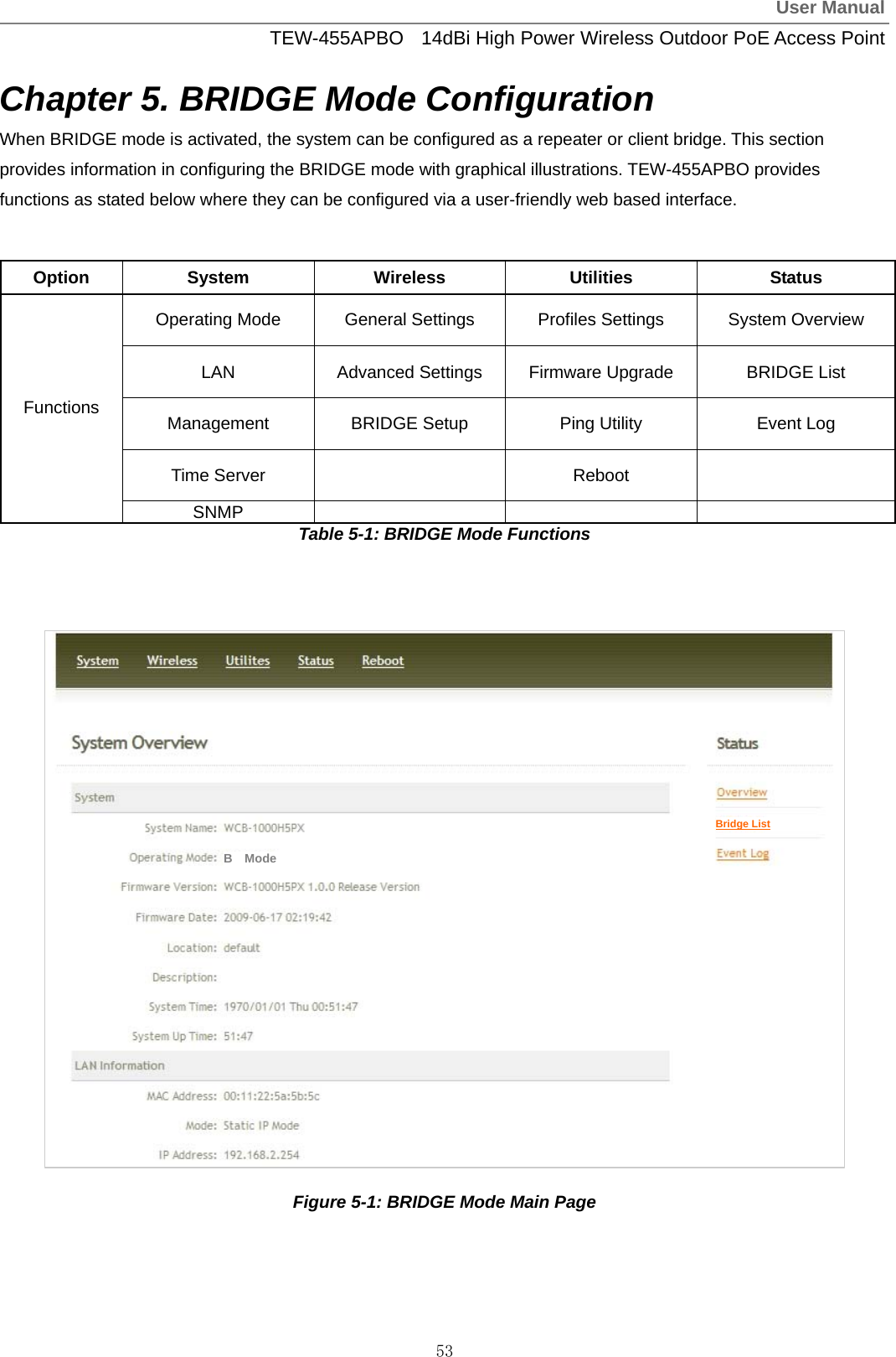
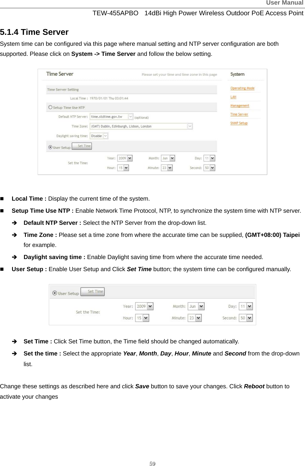
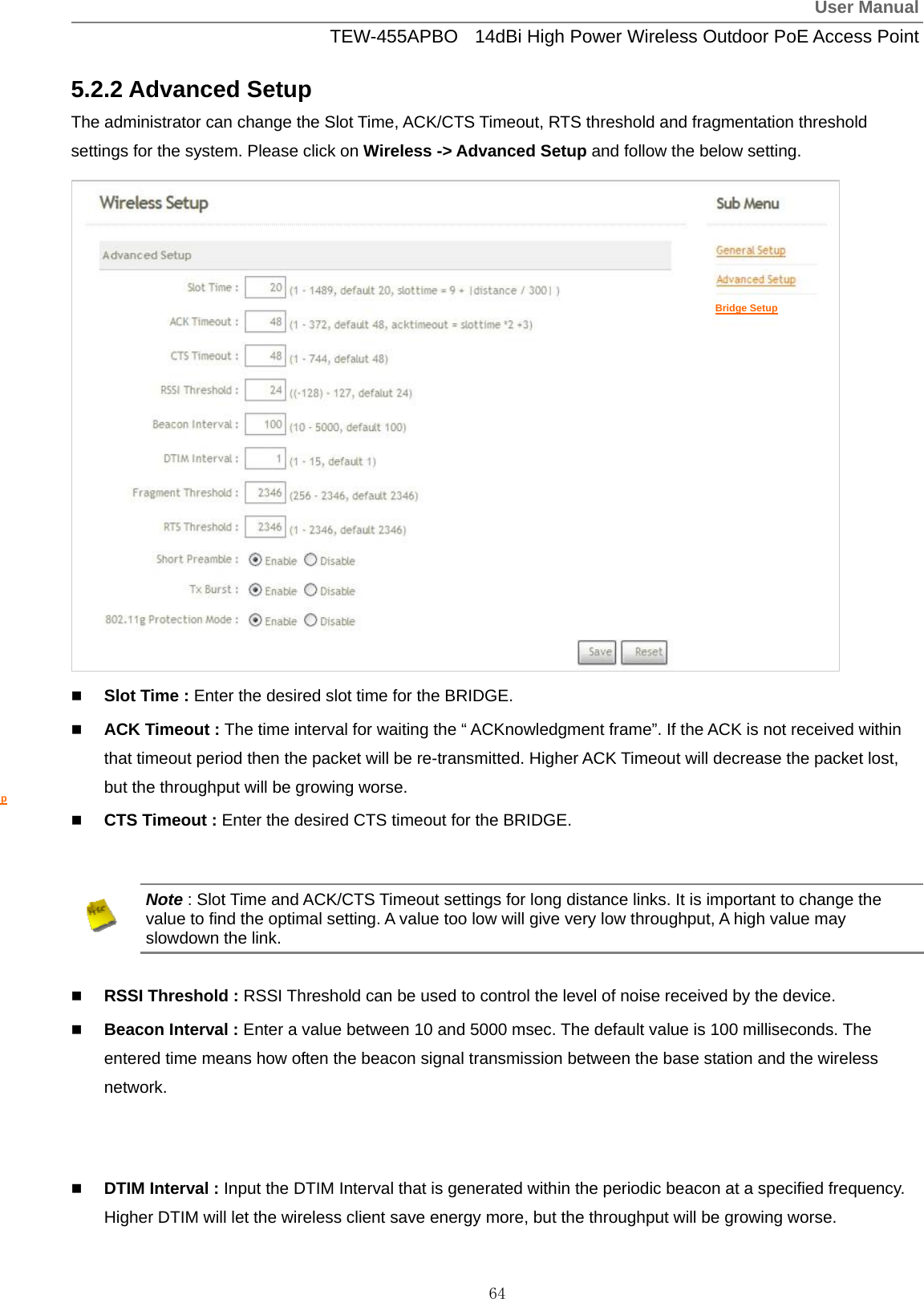
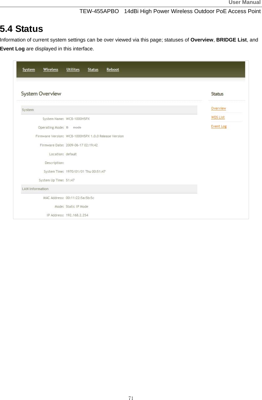
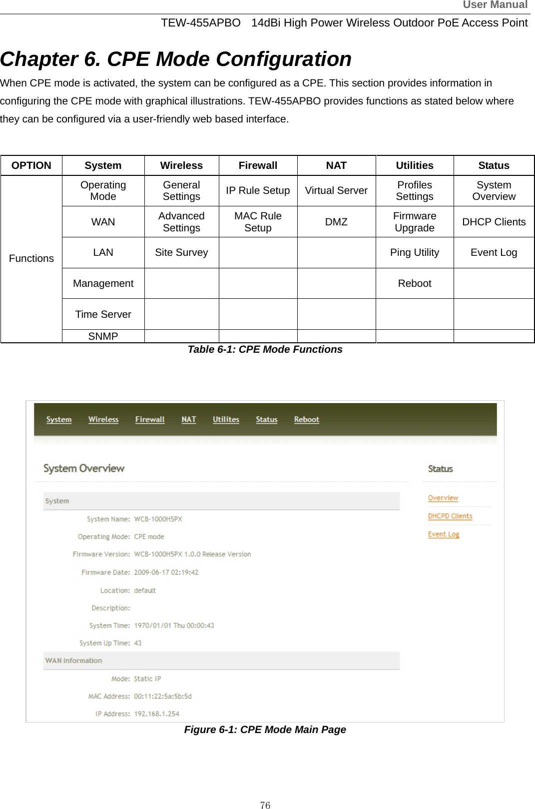
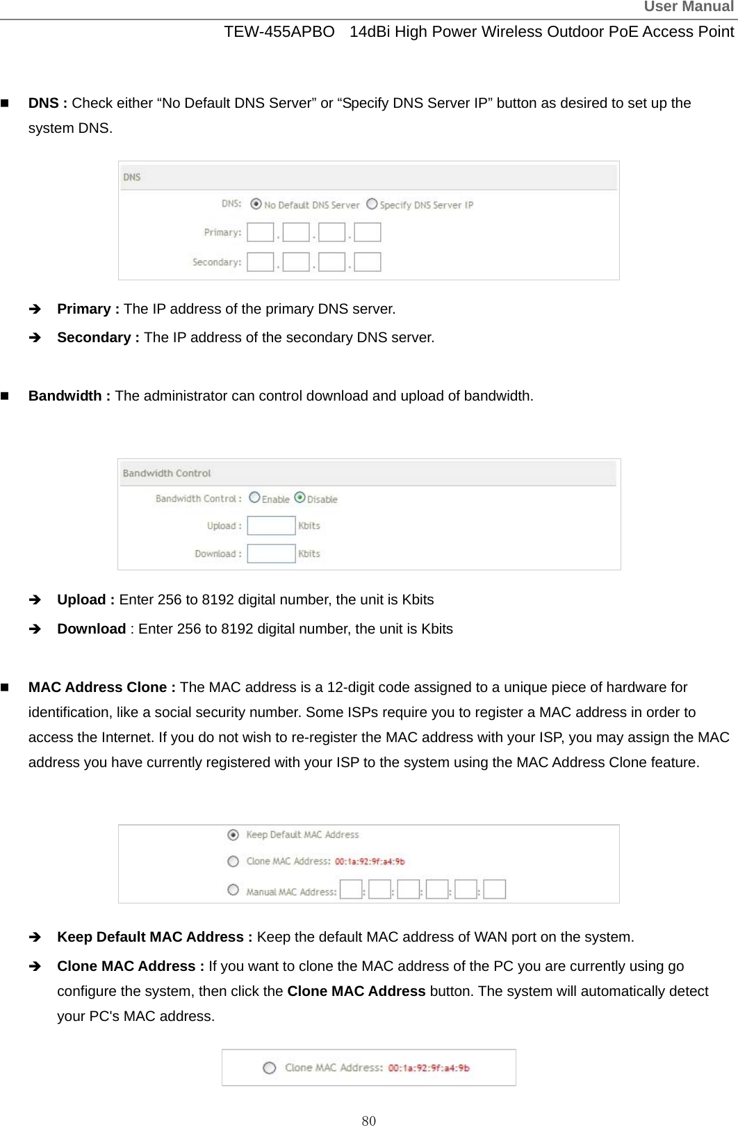
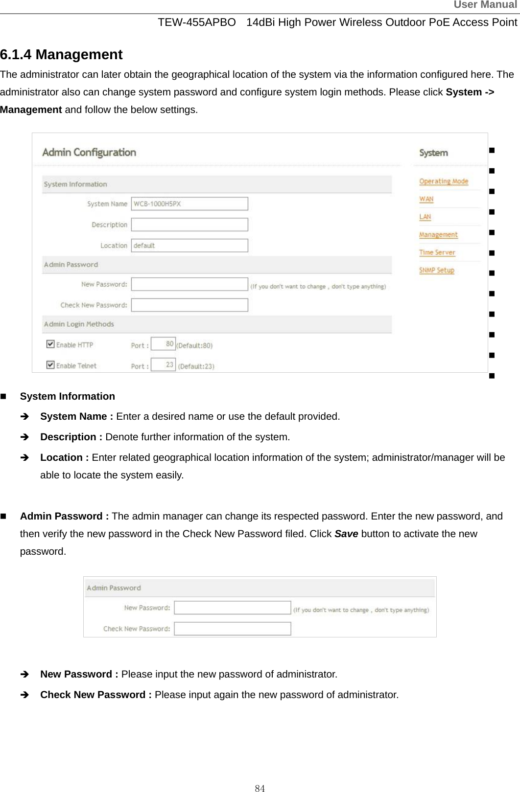
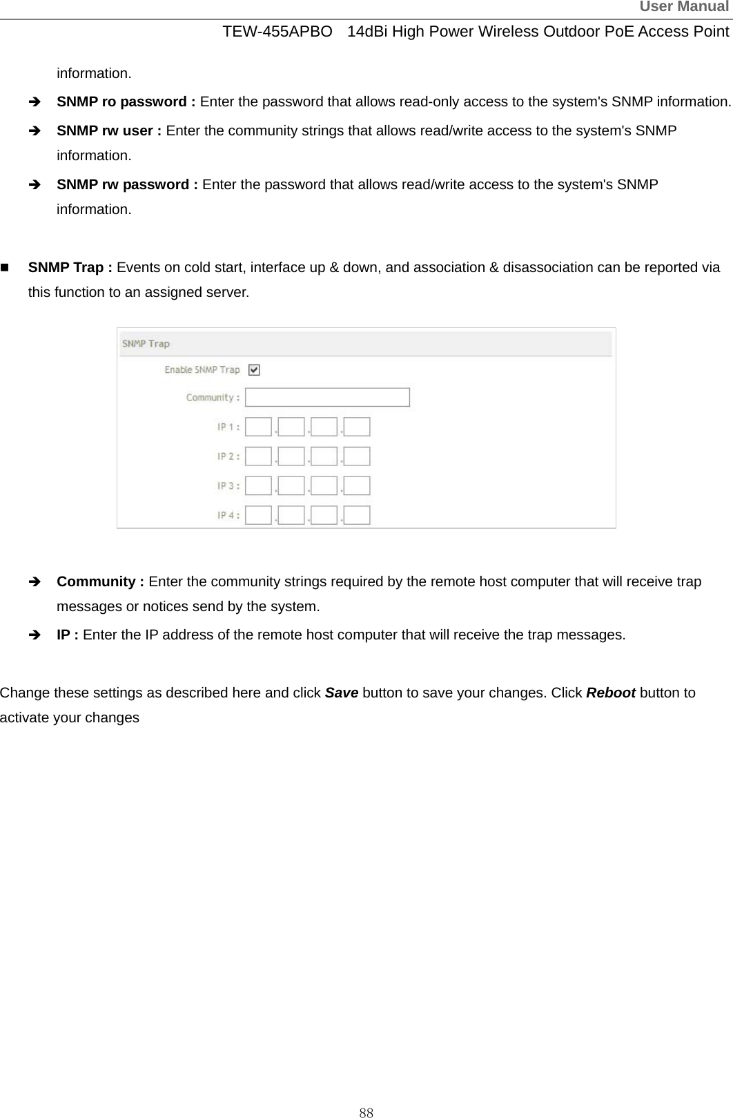
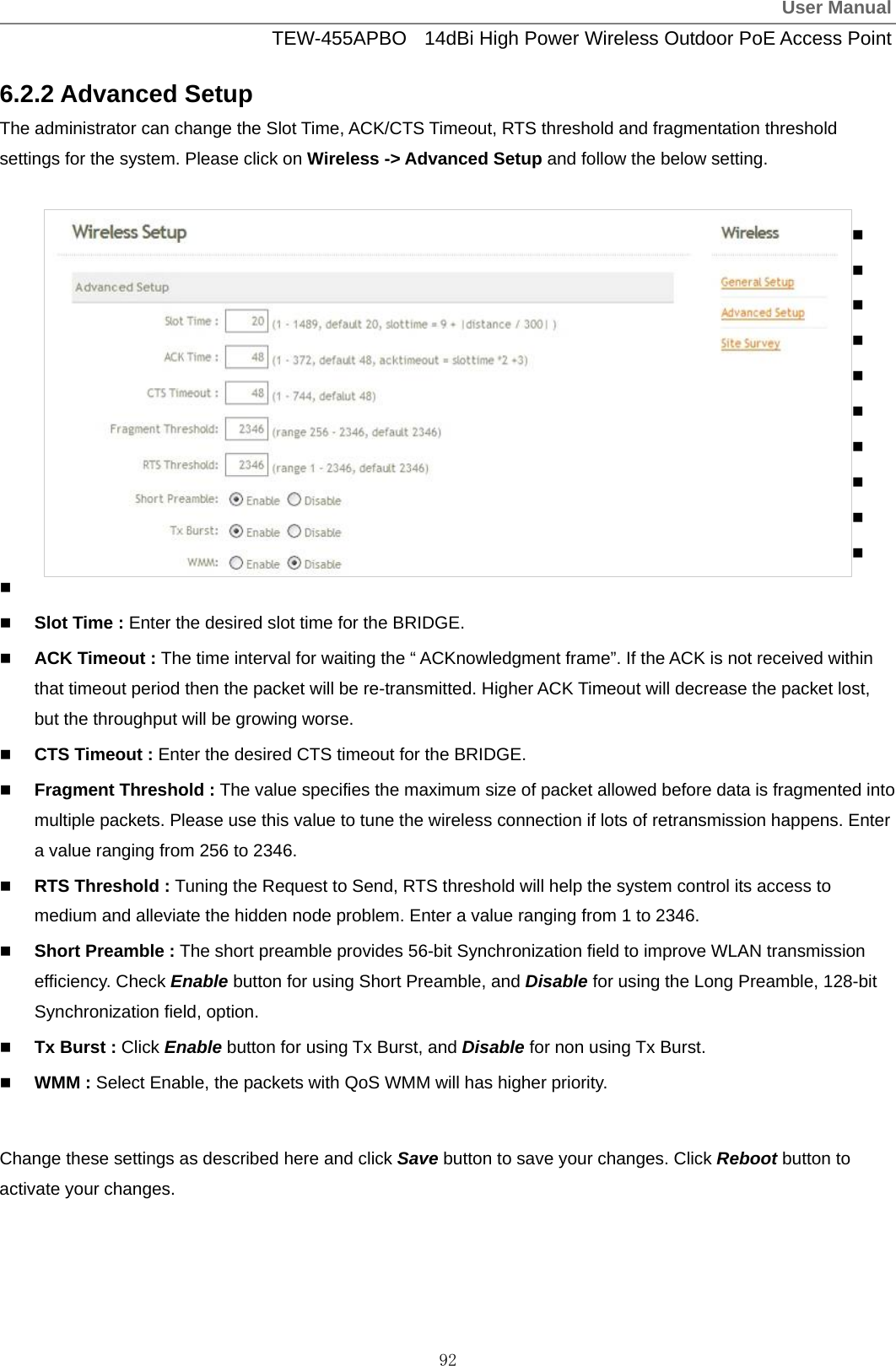
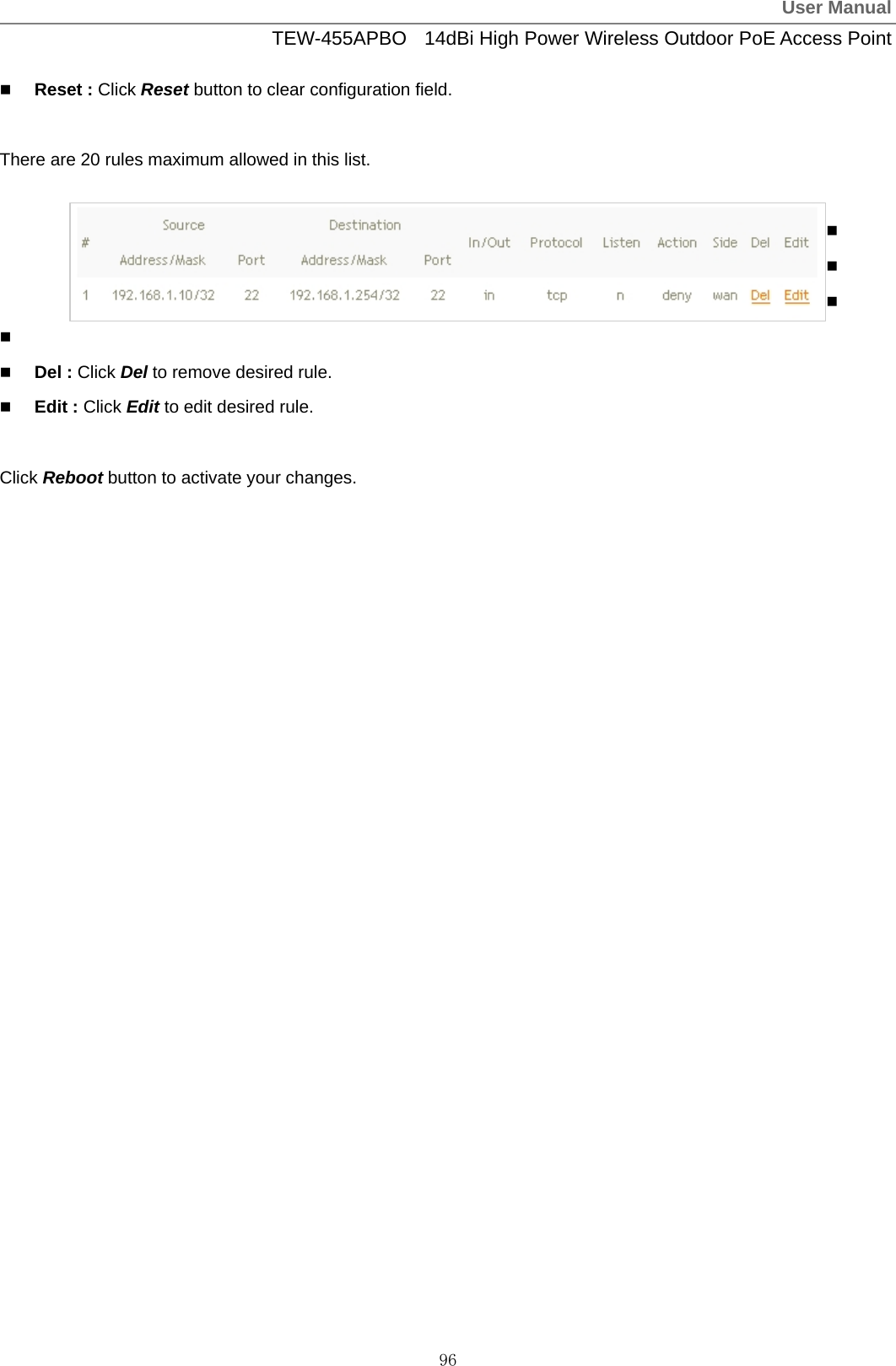
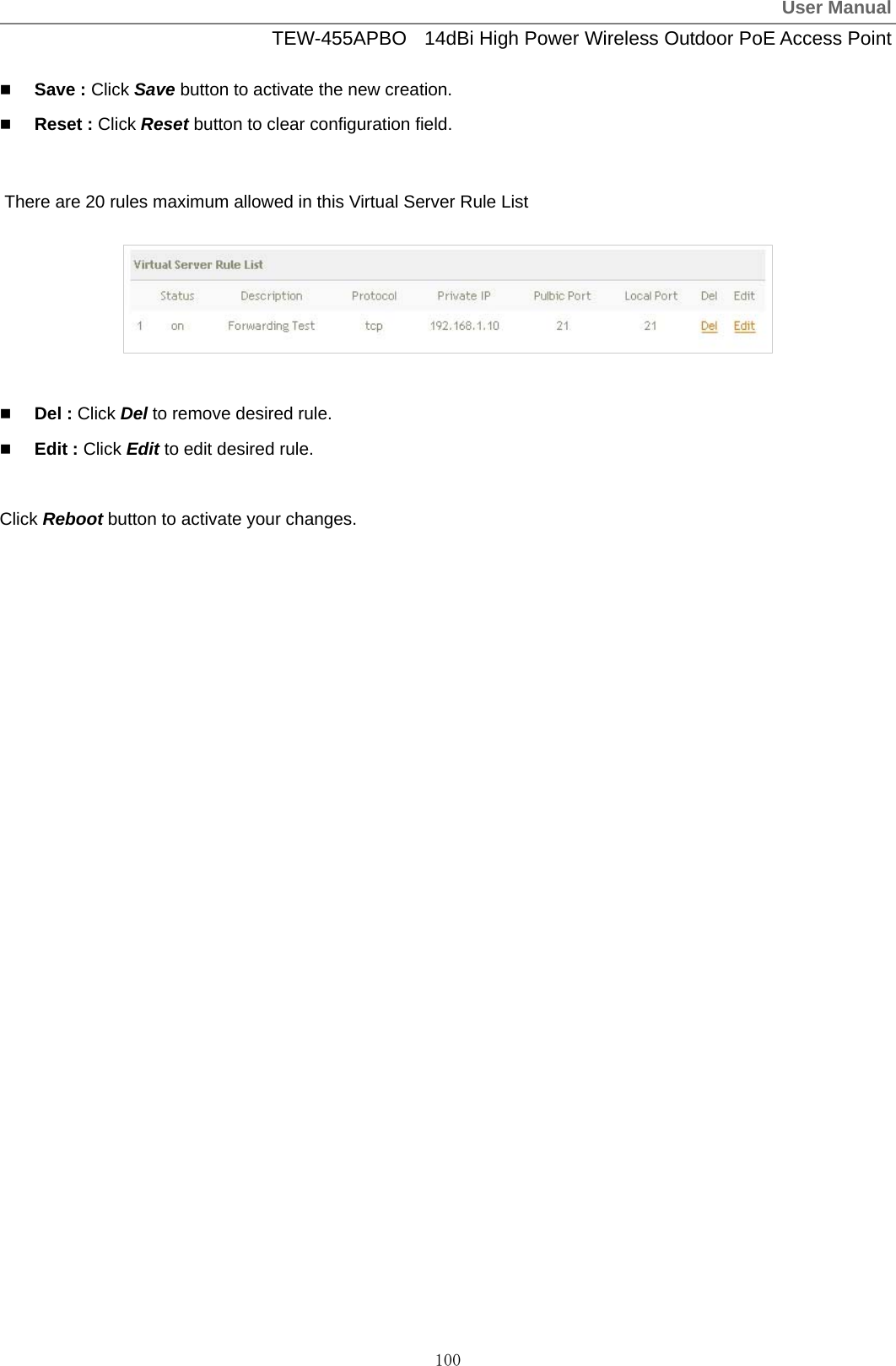
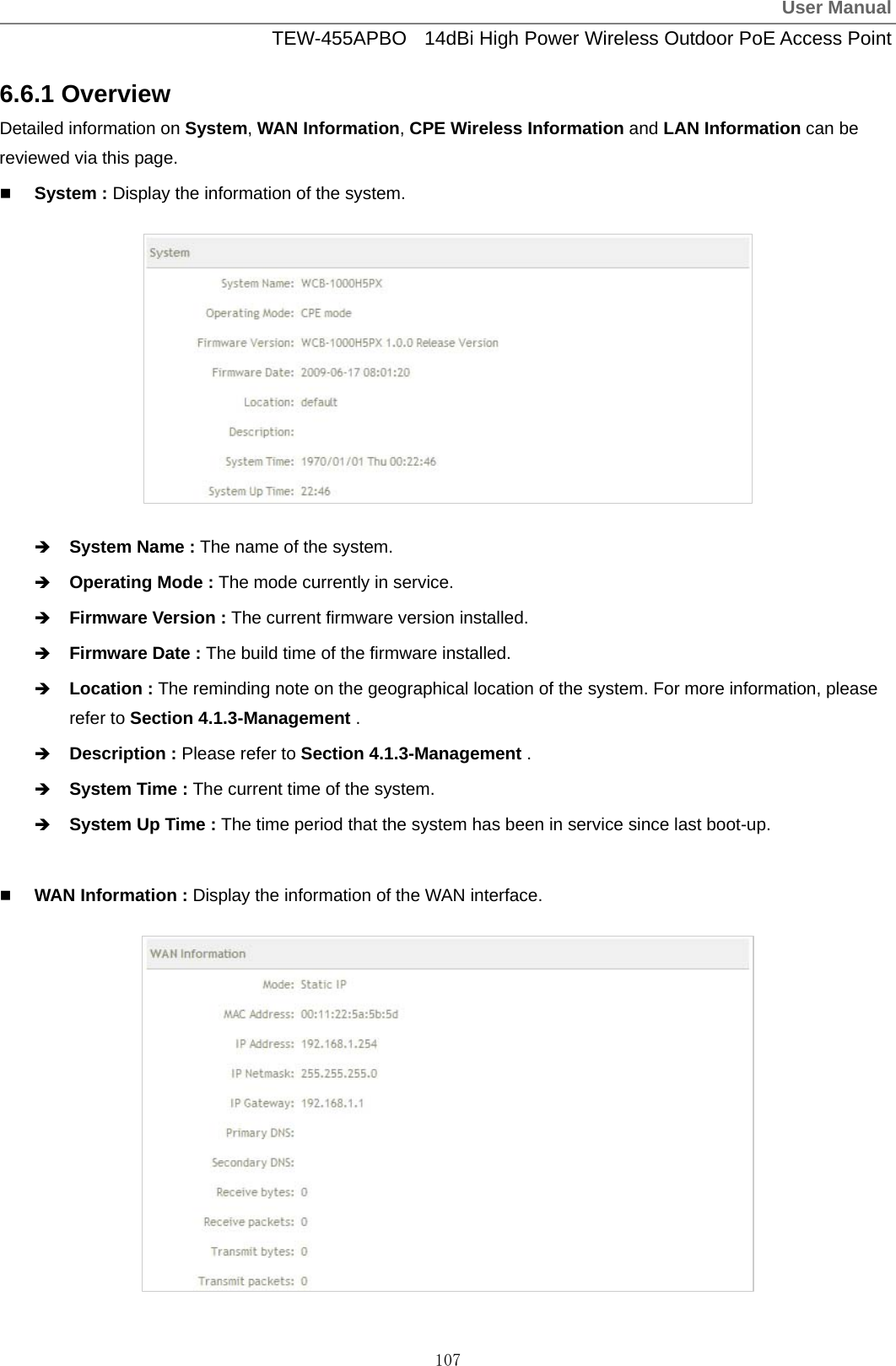
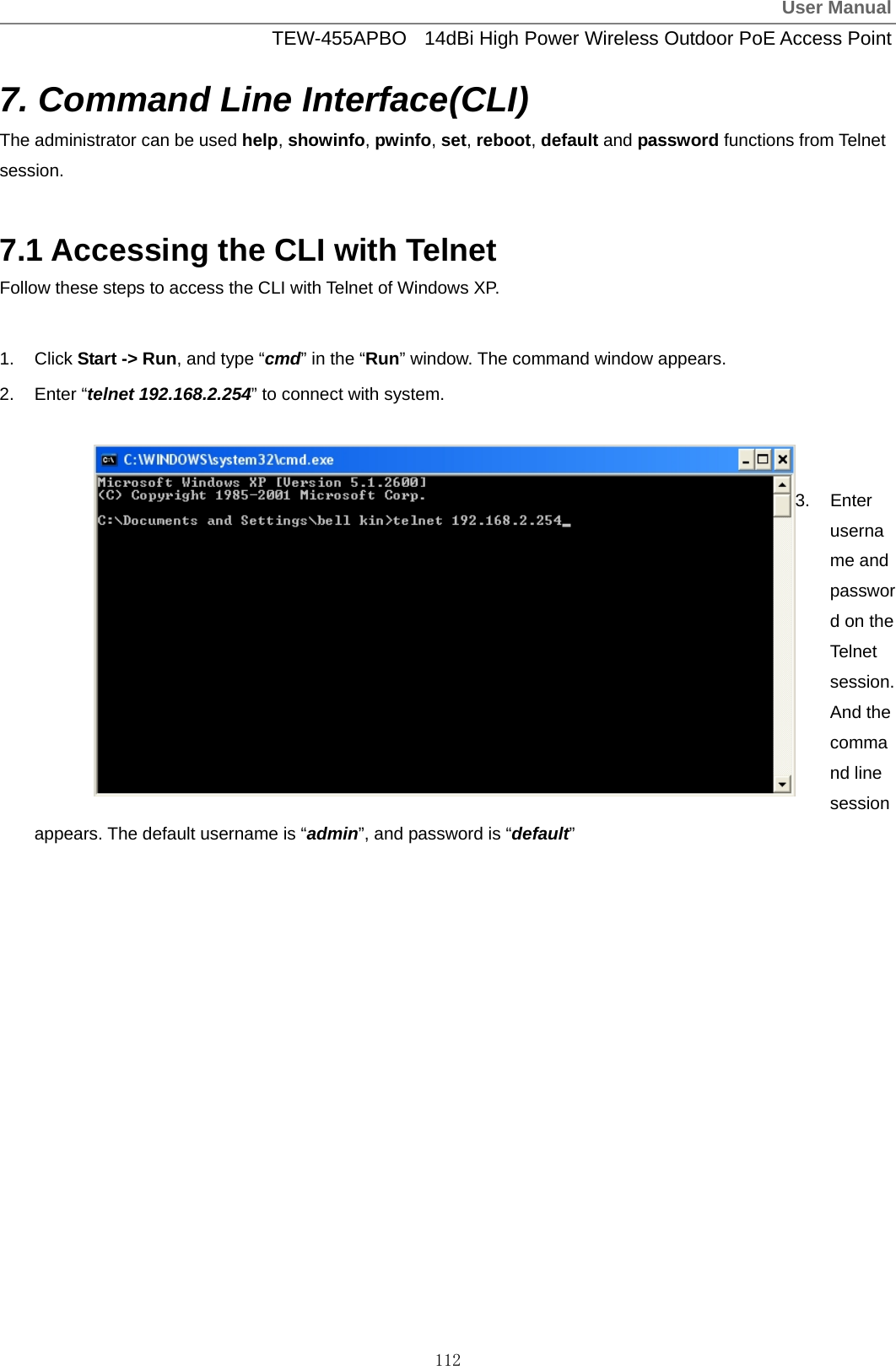
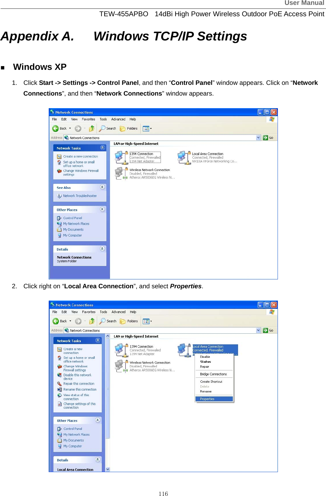
![User ManualTEW-455APBO 14dBi High Power Wireless Outdoor PoE Access Point 119 Table C Valid Characters for using WMI (continued) Block Field Valid Characters System Name Length : 32 0-9, A-Z, a-z ~ ! @ # $ % ^ * ( ) _ + - { } | : < > ? [ ] / ; ` , . = Description Length : 32 0-9, A-Z, a-z Space ~ ! @ # $ % ^ * ( ) _ + - { } | : < > ? [ ] / ; ` , . = Location Length : 32 0-9, A-Z, a-z ~ ! @ # $ % ^ * ( ) _ + - { } | : < > ? [ ] / ; ` , . = New Password Length : 4 ~ 30 0-9, A-Z, a-z ~ ! @ # $ % ^ * ( ) _ + - { } | : < > ? [ ] / ; ` , . = Check New Password Length : 4 ~ 30 0-9, A-Z, a-z ~ ! @ # $ % ^ * ( ) _ + - { } | : < > ? [ ] / ; ` , . = HTTP Port 1 ~ 65535 Management Telnet Port 1 ~ 65535 RO community Length : 32 0-9, A-Z, a-z ~ ! @ # $ % ^ * ( ) _ + - { } | : < > ? [ ] ; ` , . = RW community Length : 32 0-9, A-Z, a-z ~ ! @ # $ % ^ * ( ) _ + - { } | : < > ? [ ] ; ` , . = RO user Length : 31 0-9, A-Z, a-z ~ ! @ # $ % ^ * ( ) _ + - { } | : < > ? [ ] ; ` , . = RO password Length : 8 ~ 32 0-9, A-Z, a-z ~ ! @ # $ % ^ * ( ) _ + - { } | : < > ? [ ] ; ` , . = RW user Length : 31 0-9, A-Z, a-z ~ ! @ # $ % ^ * ( ) _ + - { } | : < > ? [ ] ; ` , . = RW password Length : 8 ~ 32 0-9, A-Z, a-z ~ ! @ # $ % ^ * ( ) _ + - { } | : < > ? [ ] ; ` , . = Community Length : 32 0-9, A-Z, a-z ~ ! @ # $ % ^ * ( ) _ + - { } | : < > ? [ ] ; ` , . = SNMP IP IP Format; 1-254](https://usermanual.wiki/TRENDNET/TEW455APBOV2/User-Guide-1253836-Page-122.png)
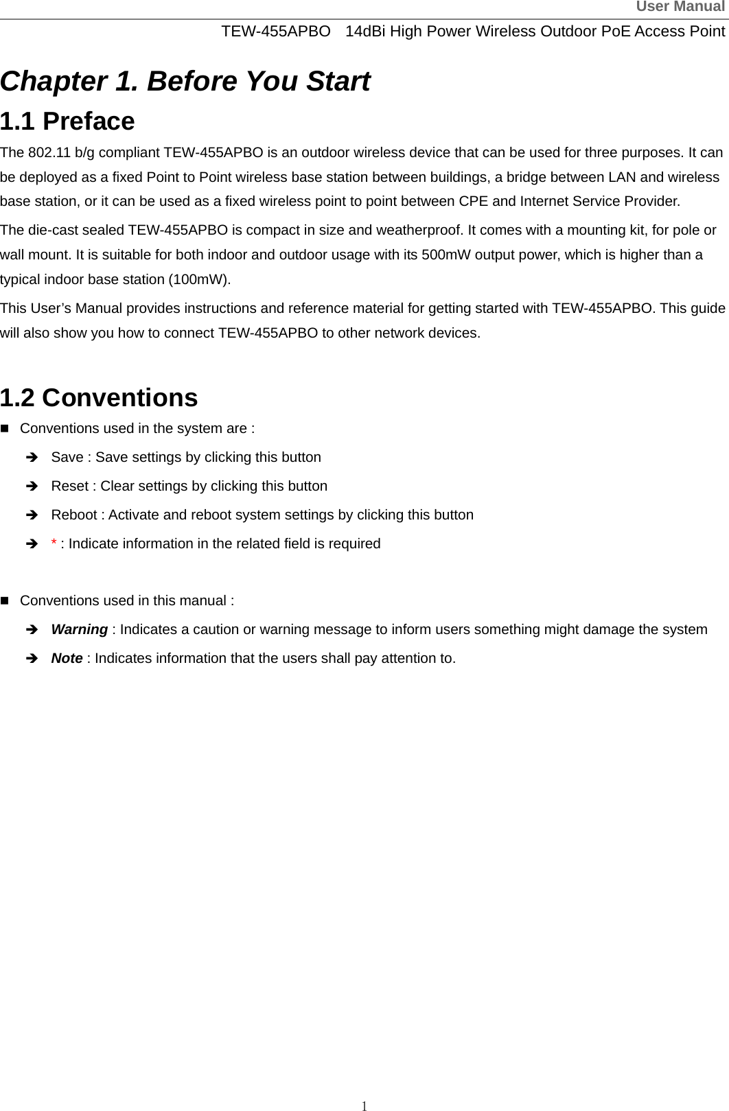
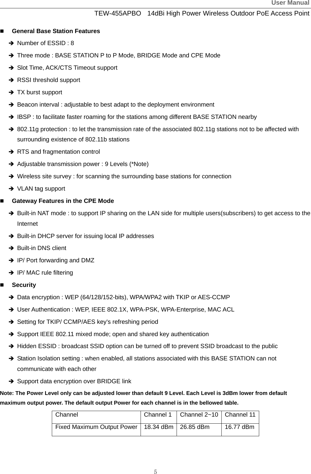
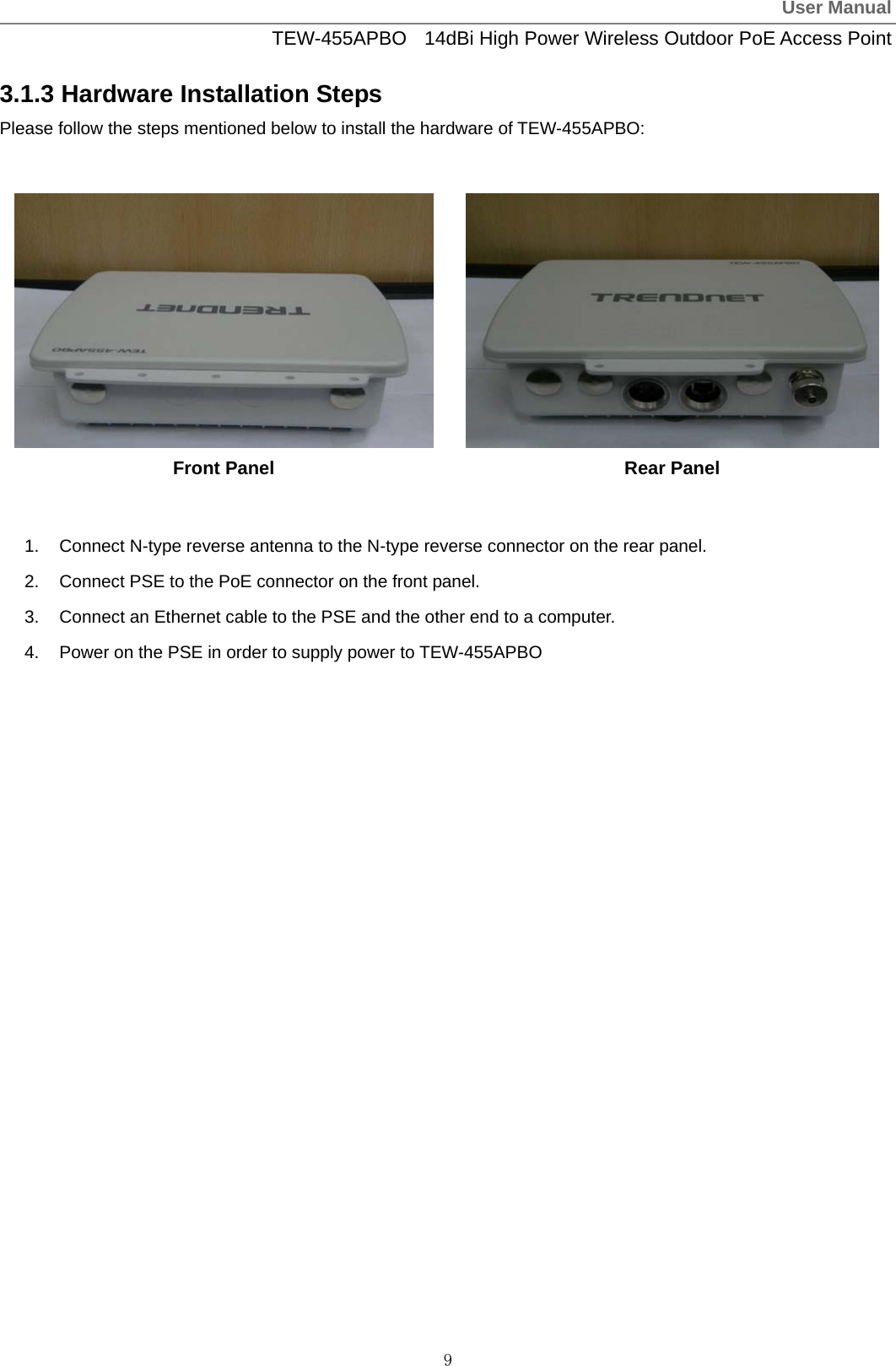
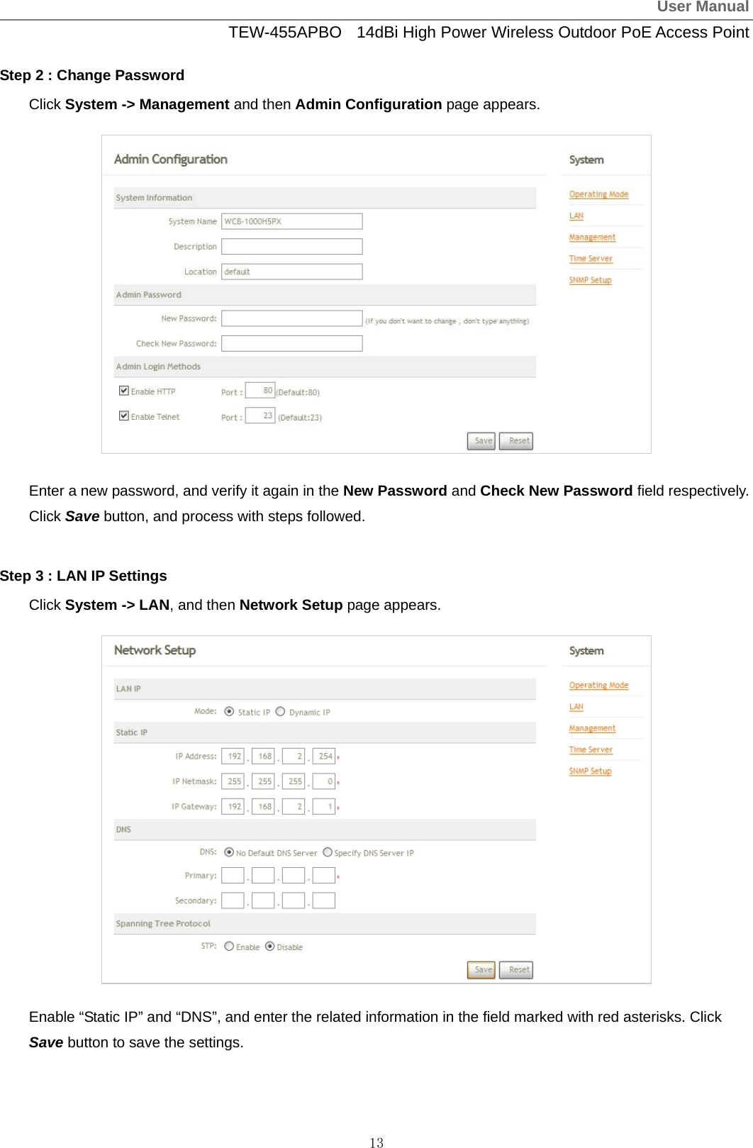
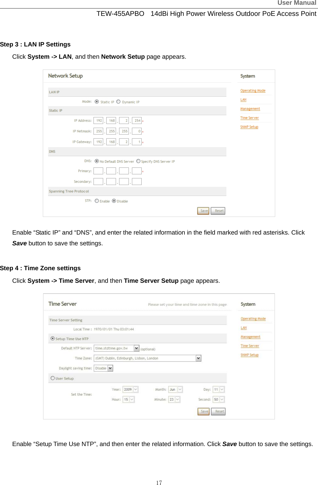
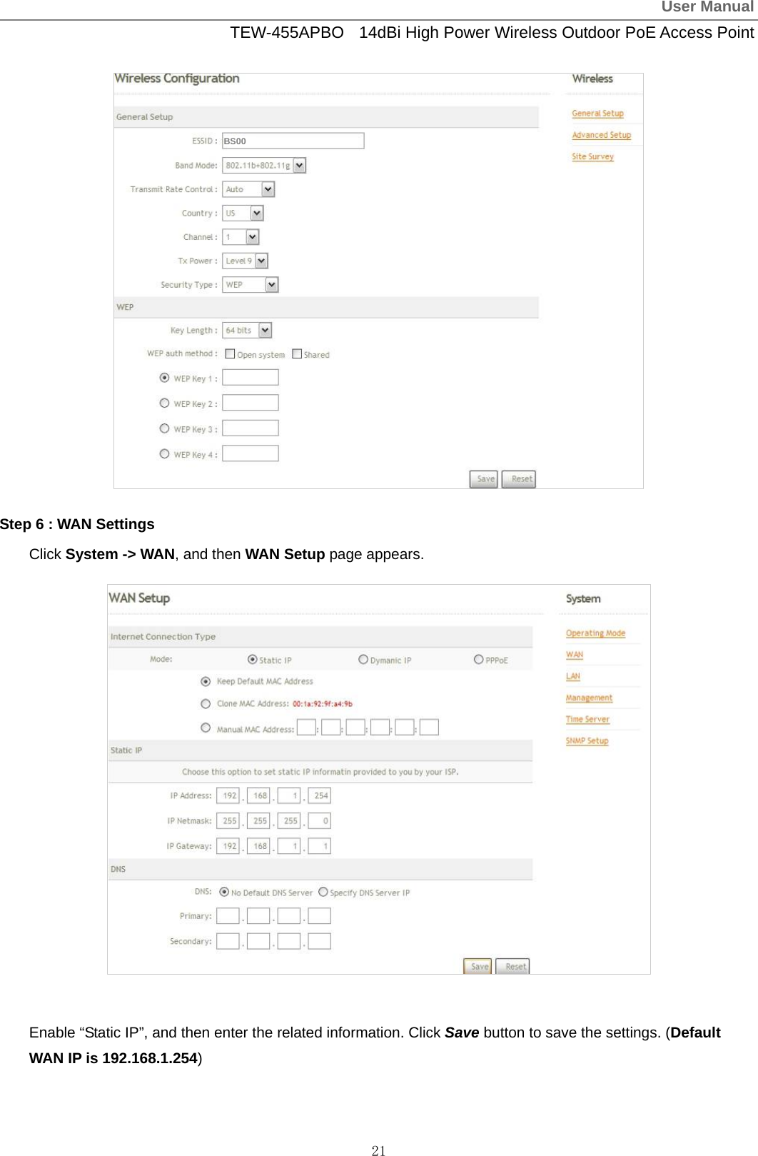
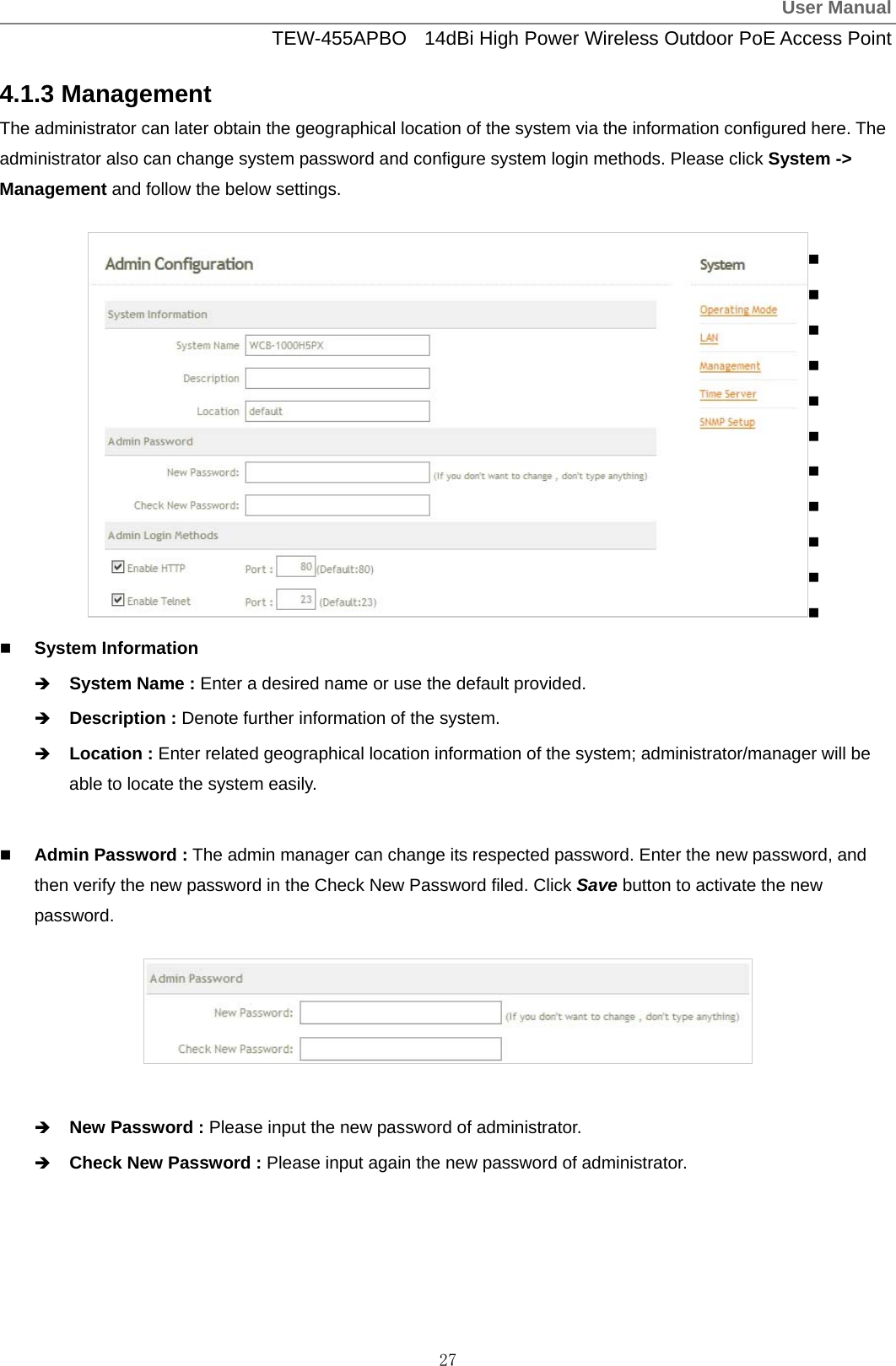
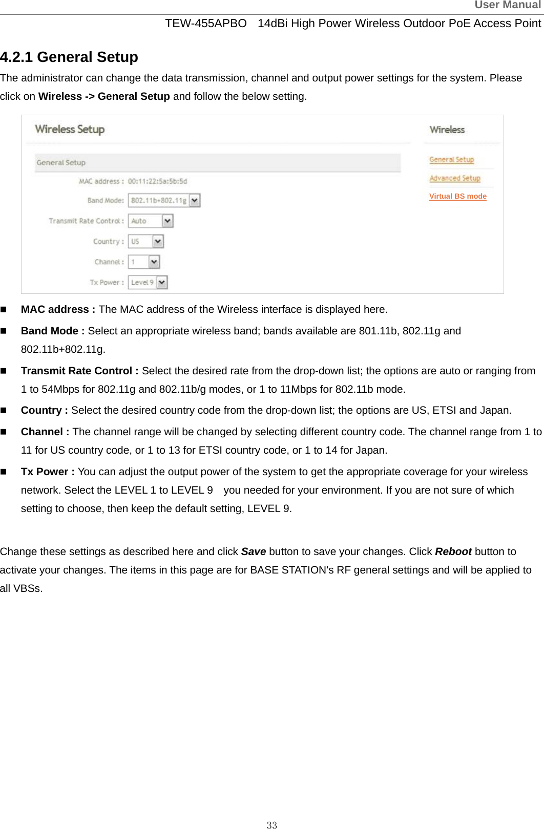
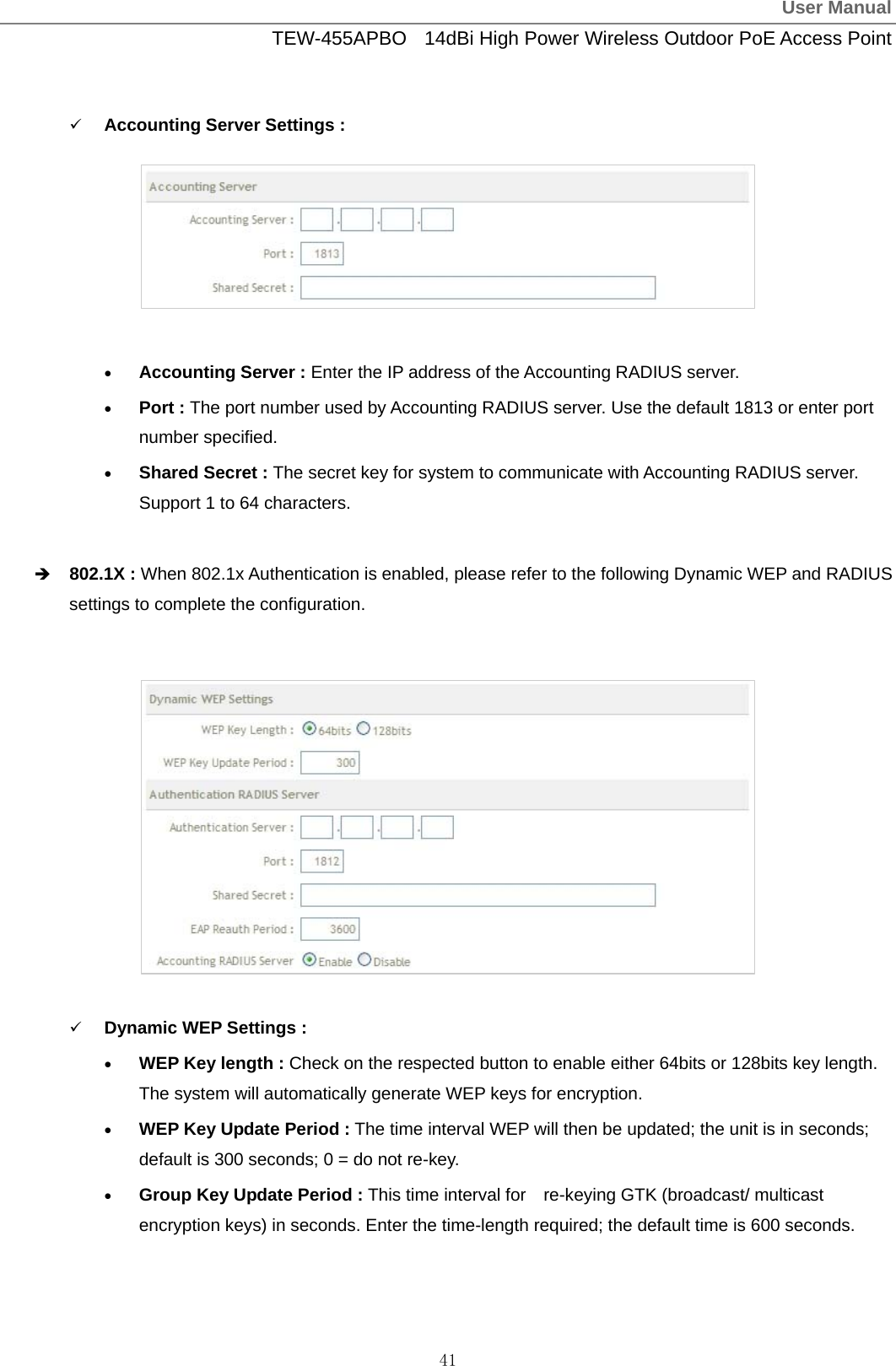
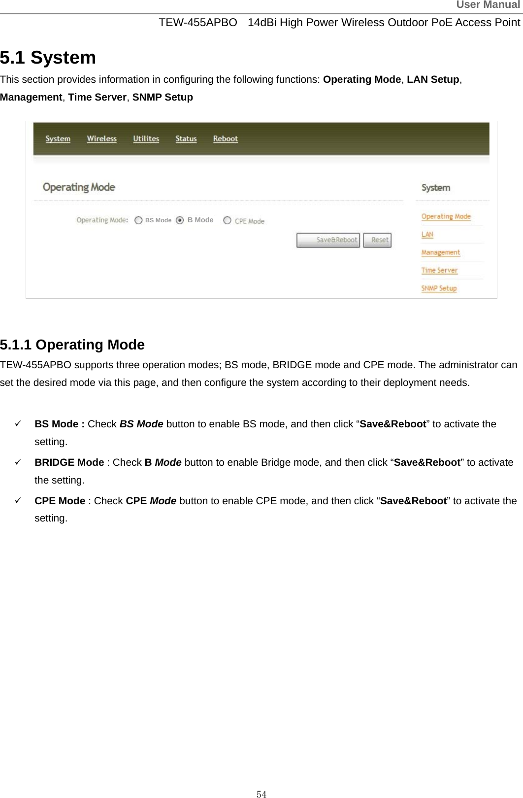
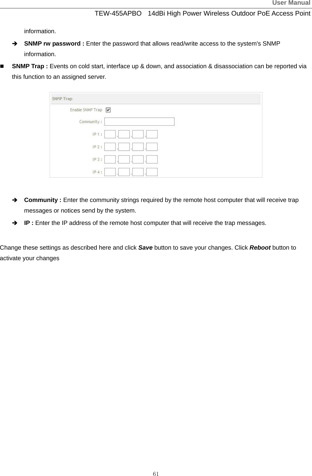
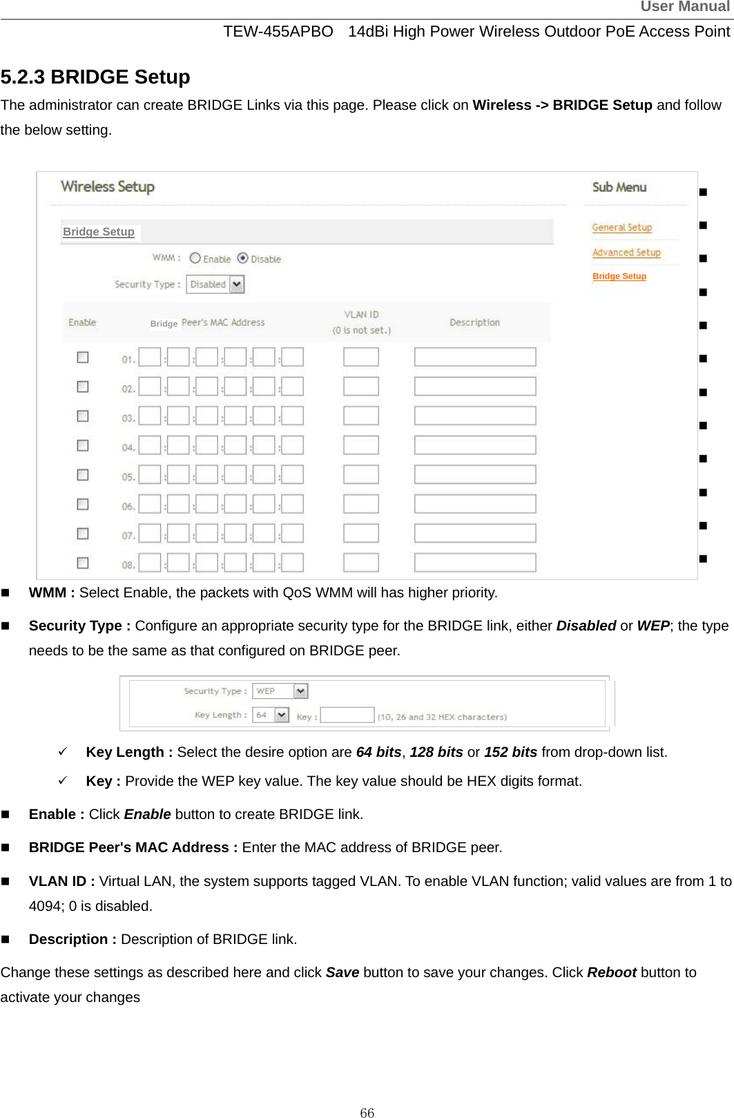
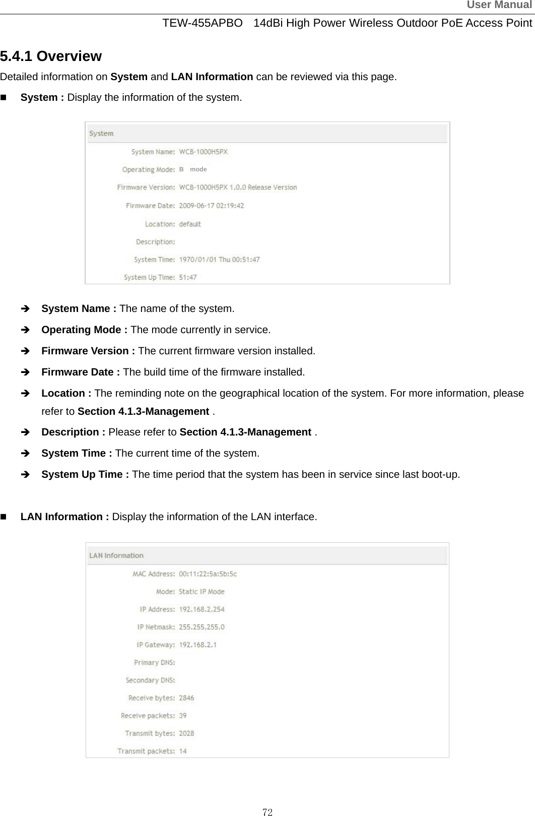
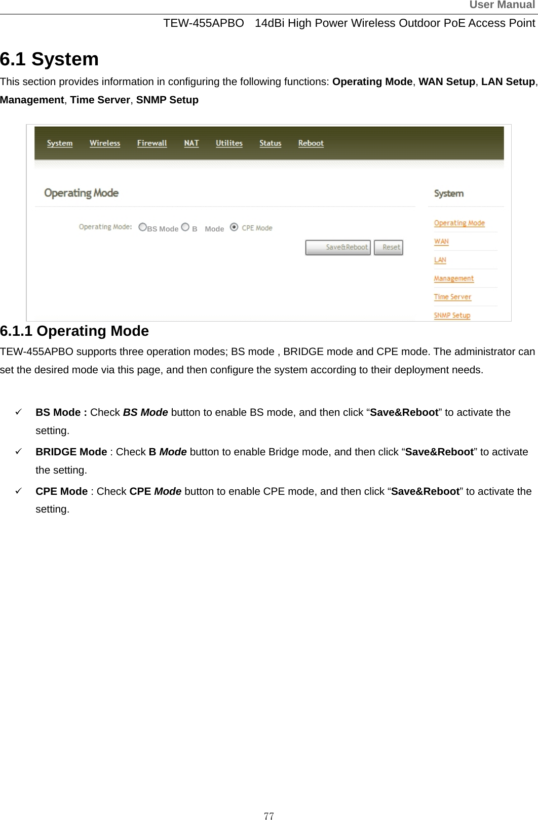
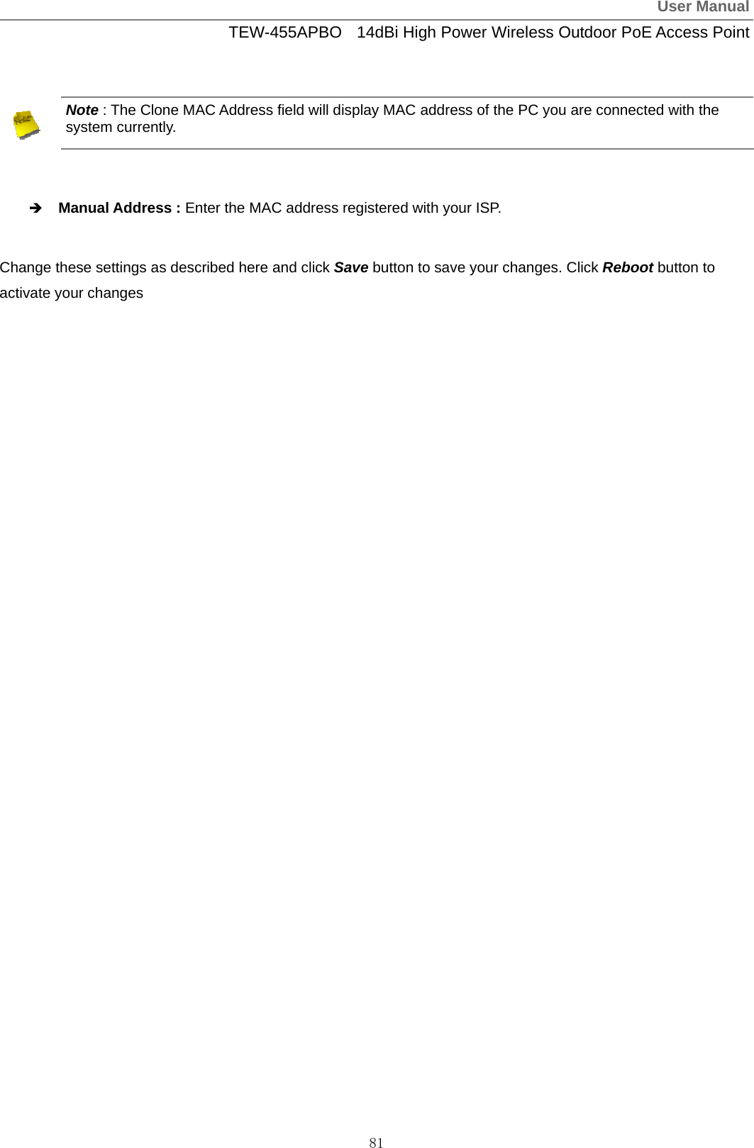
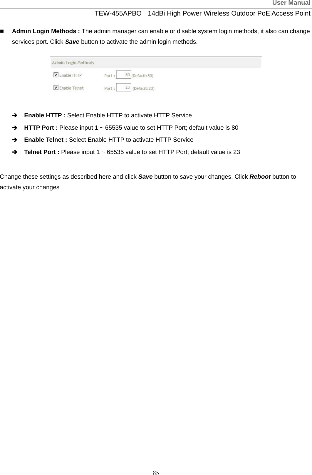
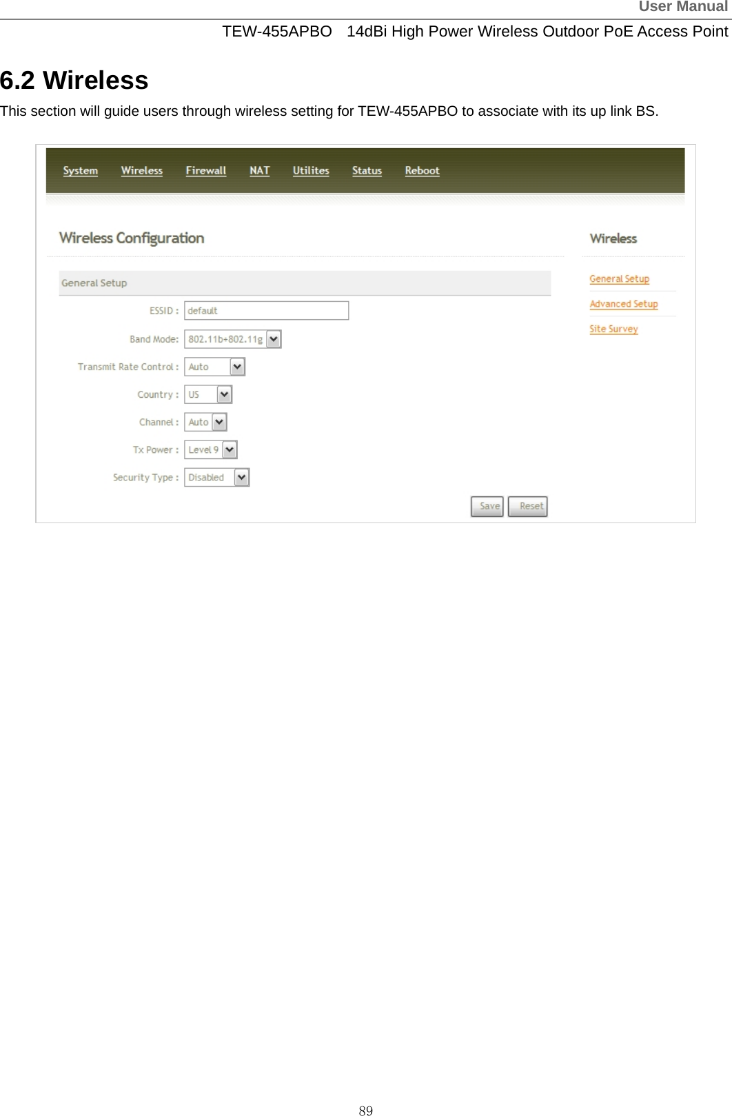
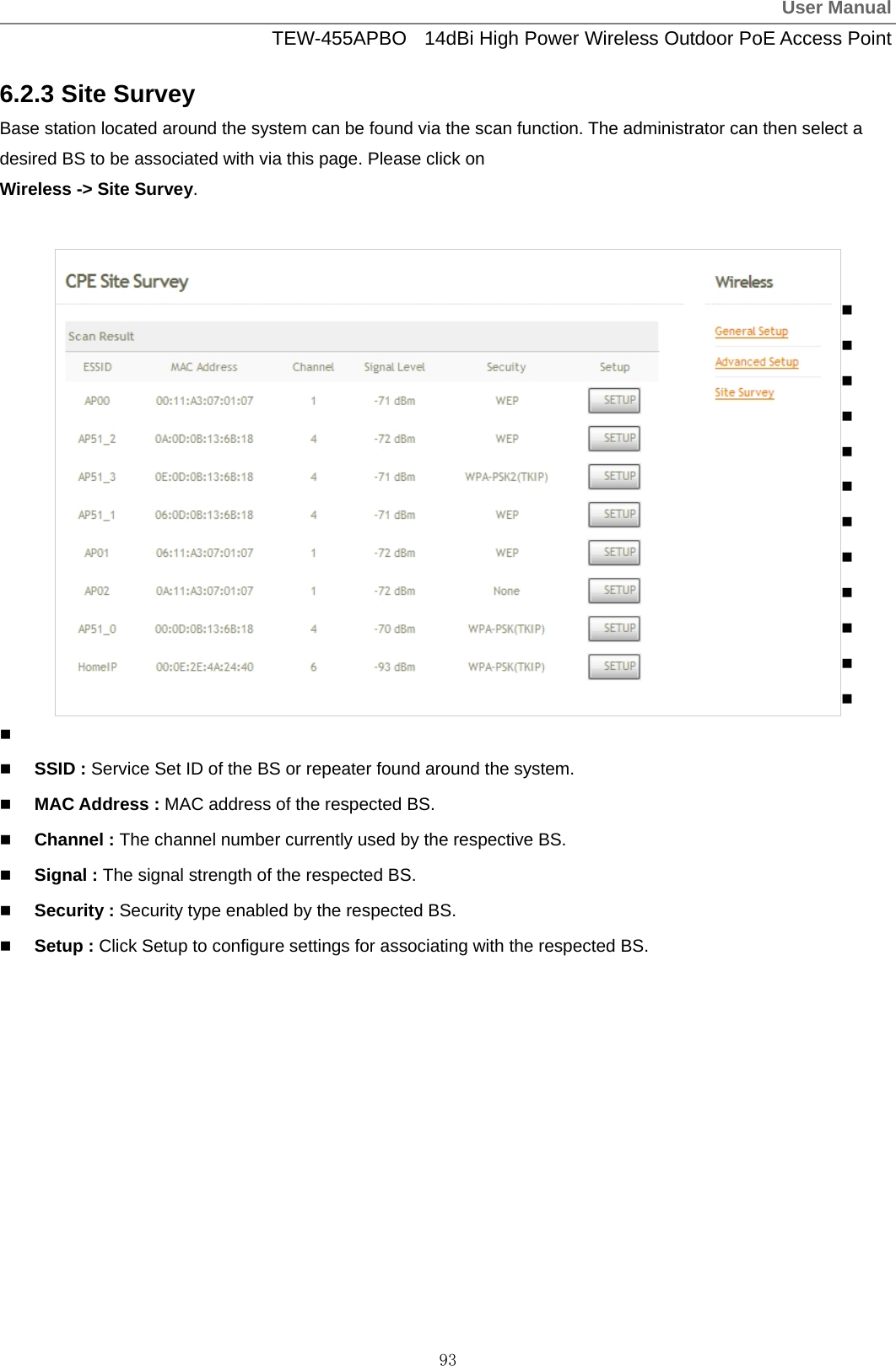
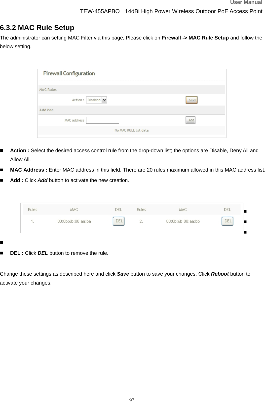
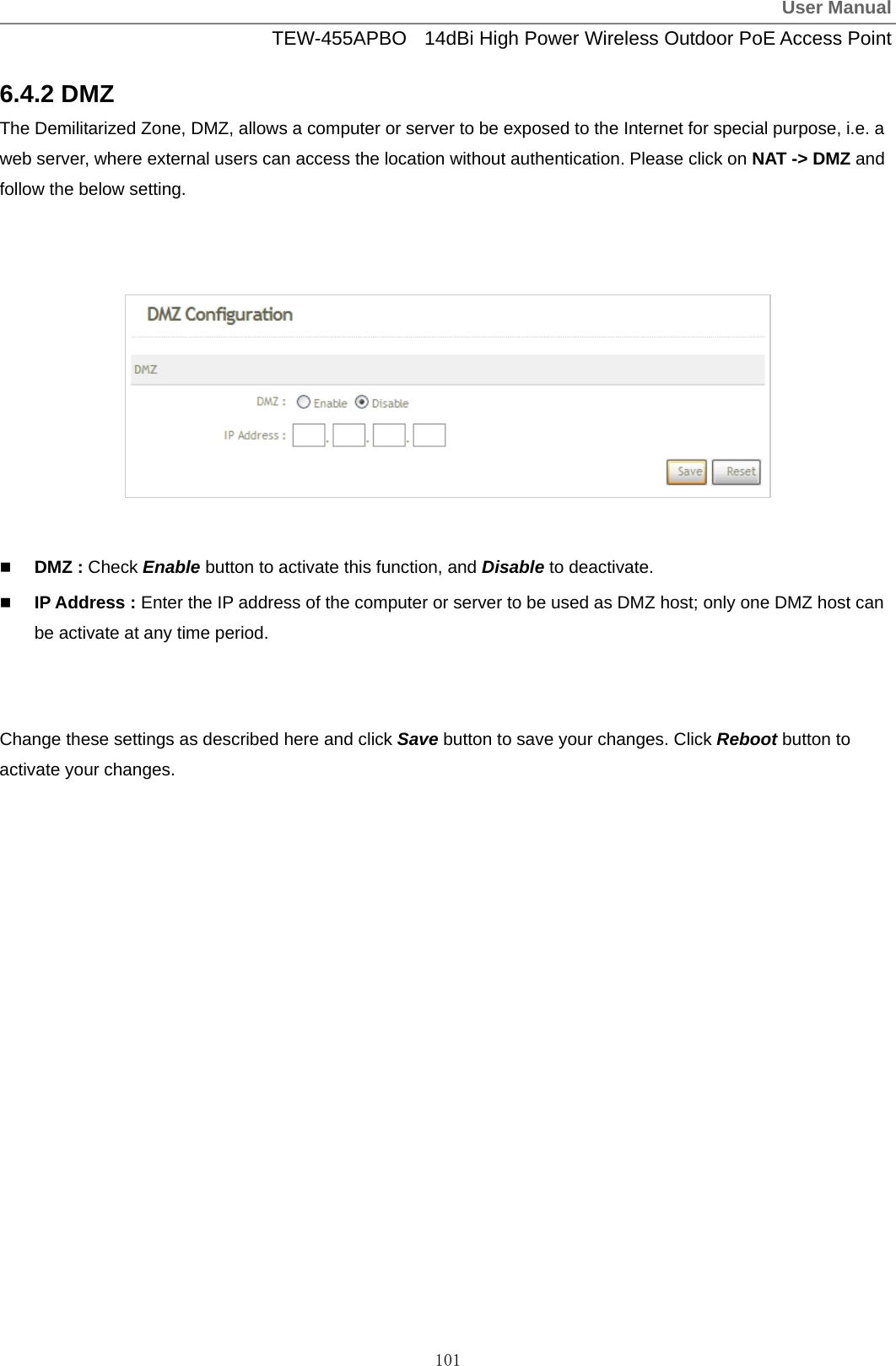
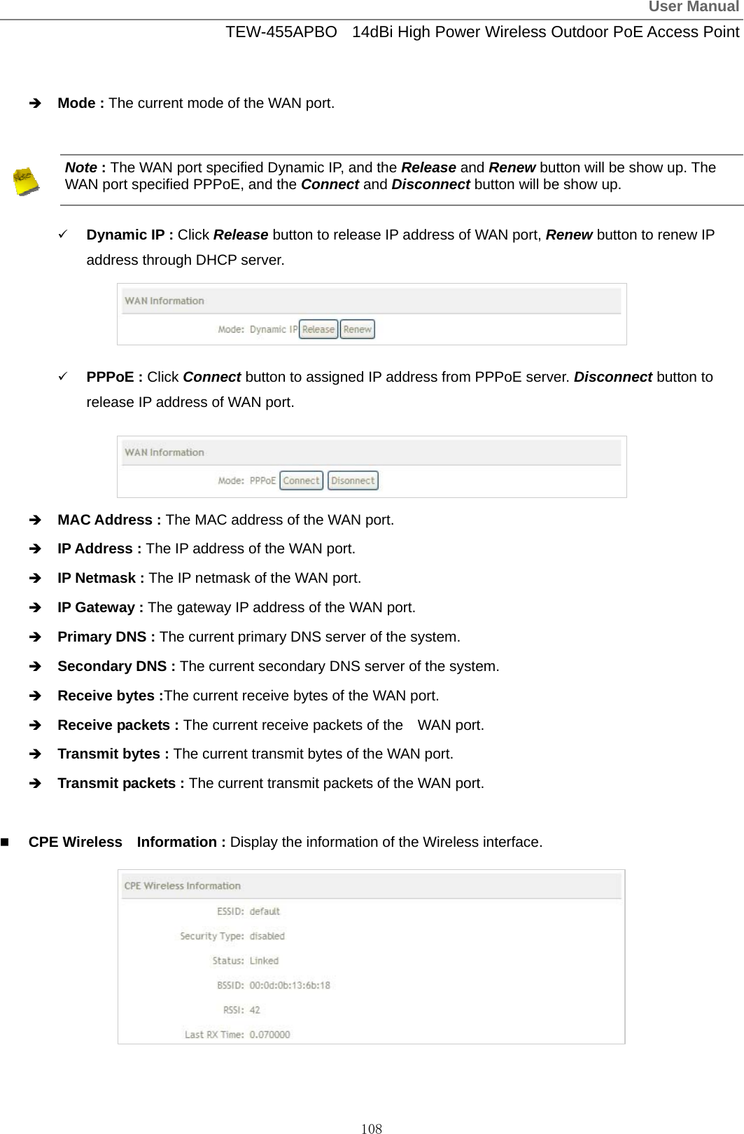
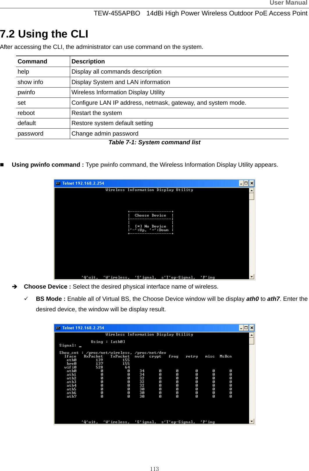
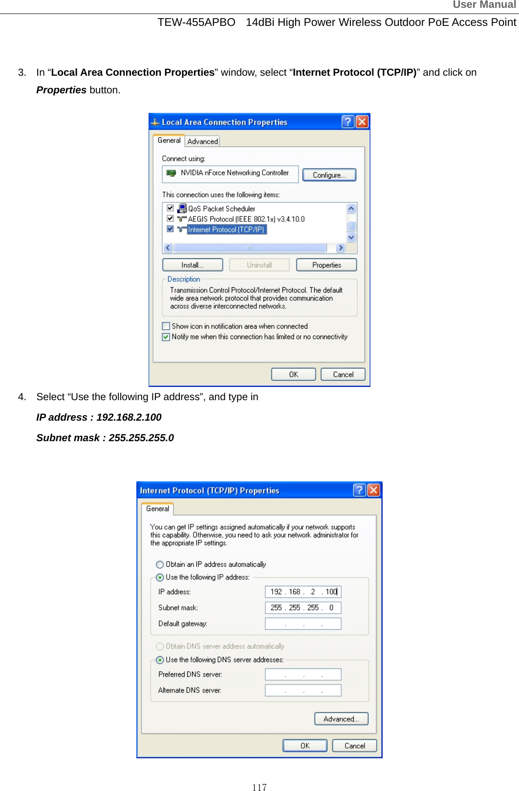
![User ManualTEW-455APBO 14dBi High Power Wireless Outdoor PoE Access Point 120 Table C Valid Characters for using WMI (continued) Block Field Valid Characters ESSID Length : 31 0-9, A-Z, a-z ~ ! @ # $ % ^ * ( ) _ + - { } | : < > ? [ ] / ; ` , . = WEP Key 10, 26, 32 HEX chars General Setup (CPE Mode) Shared Key 1 ~ 63 ASCII chars; 64 HEX chars Slot Time 1 ~ 1489 ACK Time 1 ~ 372 CTS Time 1 ~ 744 RSSI Threshold -128 ~ 127 Beacon Interval 10 ~ 5000 Date Beacon Rate 1 ~ 15 Fragment Threshold 256 ~ 2346 Advanced Setup (BS&BRIDGE Mode) RTS Threshold 1 ~ 2346 Slot Time 1 ~ 1489 ACK Time 1 ~ 372 CTS Time 1 ~ 744 Fragment Threshold 256 ~ 2346 Advanced Setup (CPE Mode) RTS Threshold 1 ~ 2346 ESSID Length : 31 0-9, A-Z, a-z ~ ! @ # $ % ^ * ( ) _ + - { } | : < > ? [ ] / ; ` , . = Maximum Clients 1 ~ 32 VLAN ID 1 ~ 4094 ; 0 is disable Pass phrase 5, 13, 16 ASCII chars WEP Key 10, 26, 32 HEX chars Group Key Update 10 ~ 99999999 seconds Master Key Update 10 ~ 99999999 seconds Pre-Shared Key 8 ~ 63 ASCII chars; 64 HEX chars Authentication Server IP Format; 1-254 Authentication Port 1 ~ 65535 Shared Secret 1 ~ 64 characters EAP Reauth Period 300 ~ 99999999; default is 3600, 0 is disable Accounting Server IP Format; 1-254 Accounting Port 1 ~ 65535 Virtual BS Setup WEP Key Update 0 ~ 99999999 ; default is 300, 0 is disable](https://usermanual.wiki/TRENDNET/TEW455APBOV2/User-Guide-1253836-Page-123.png)
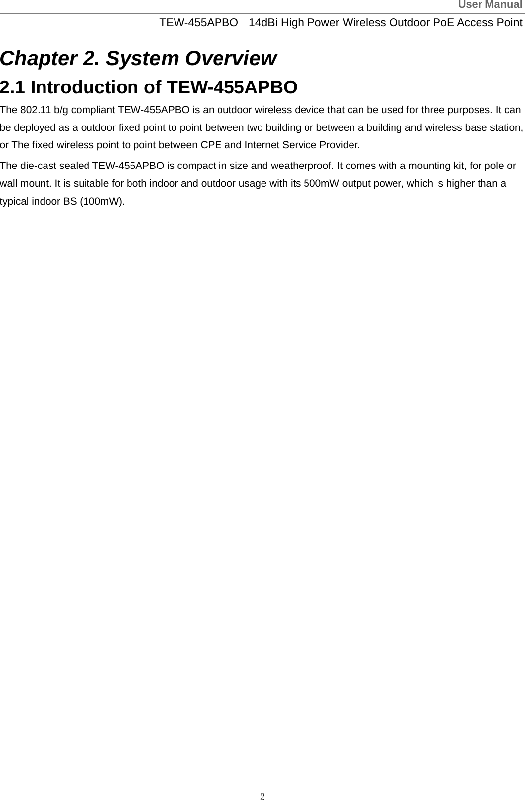
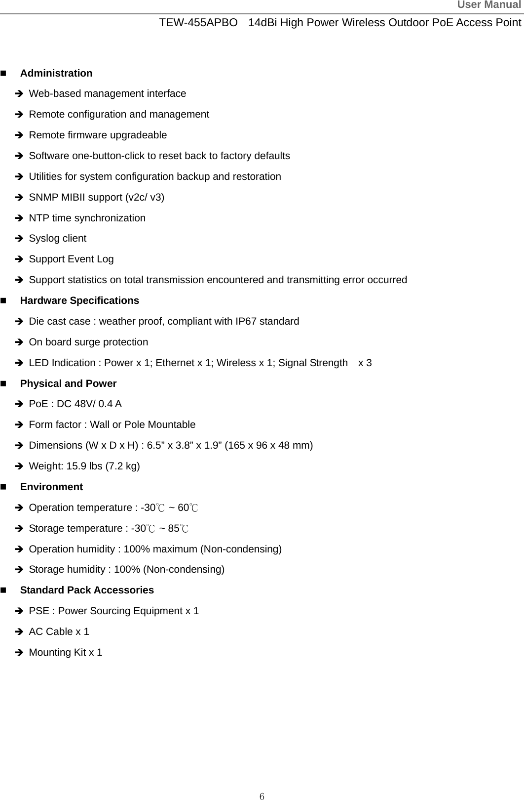
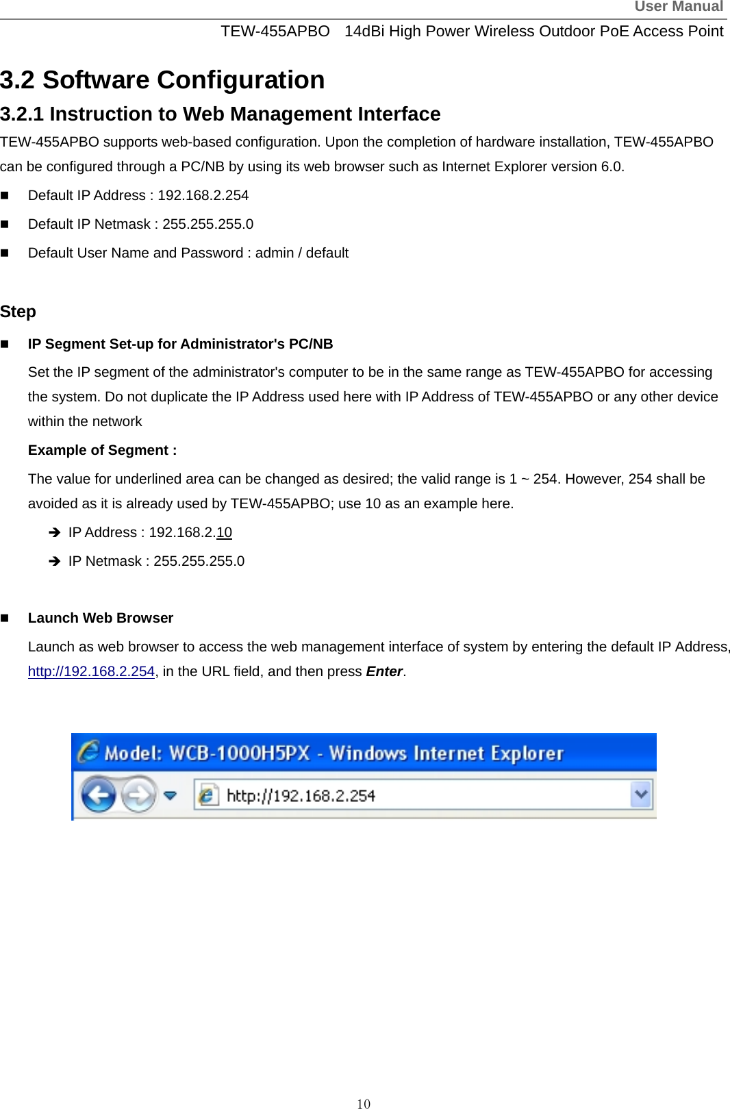
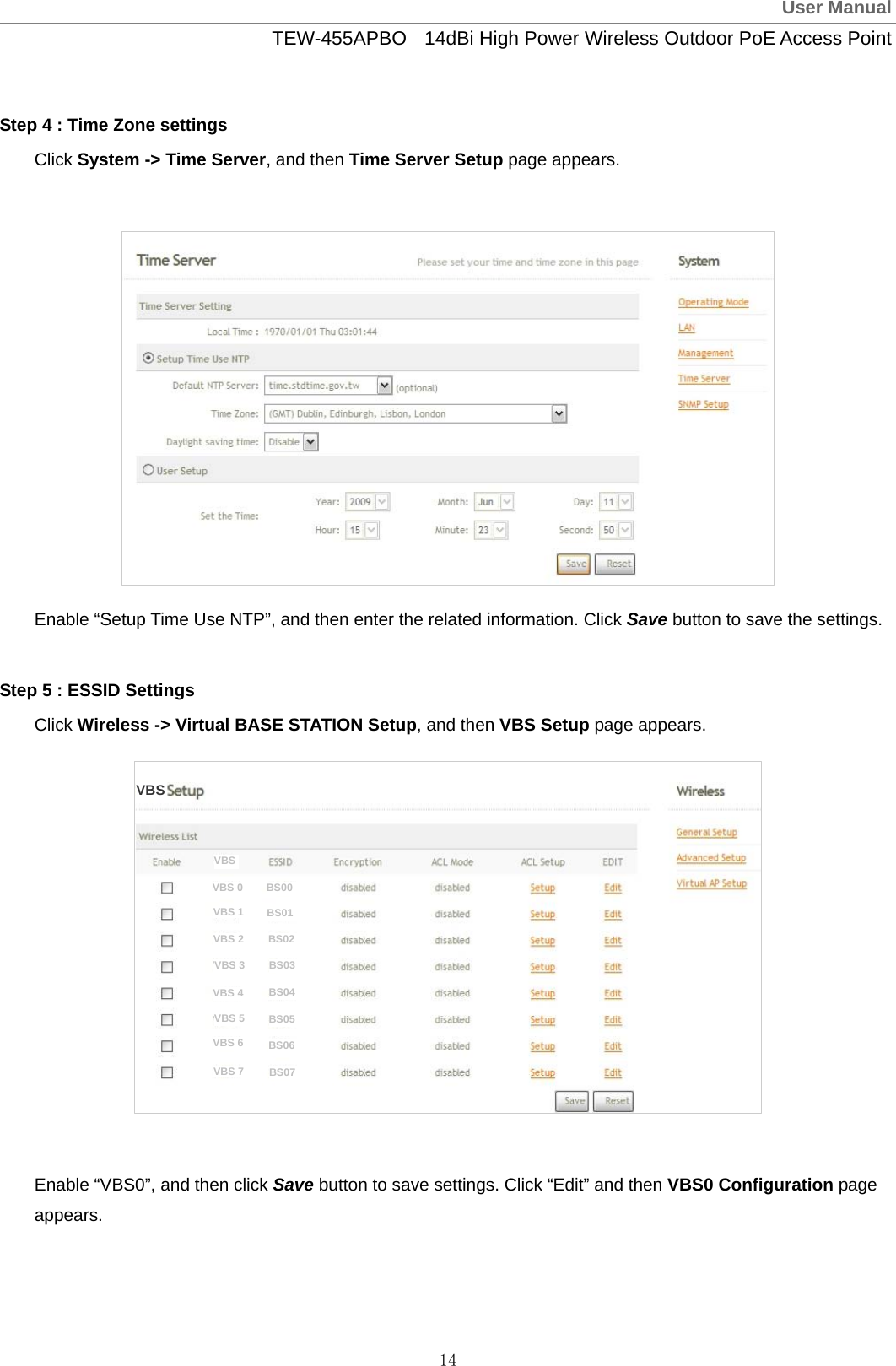
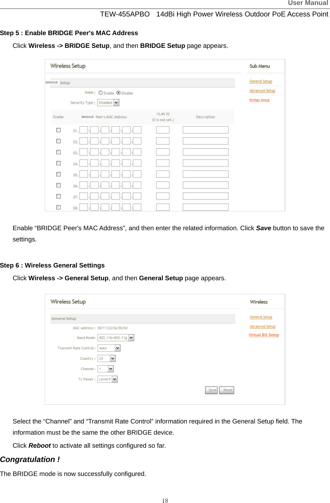
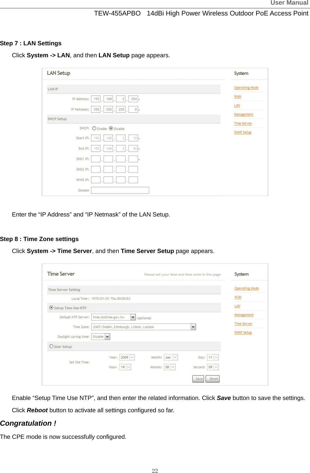
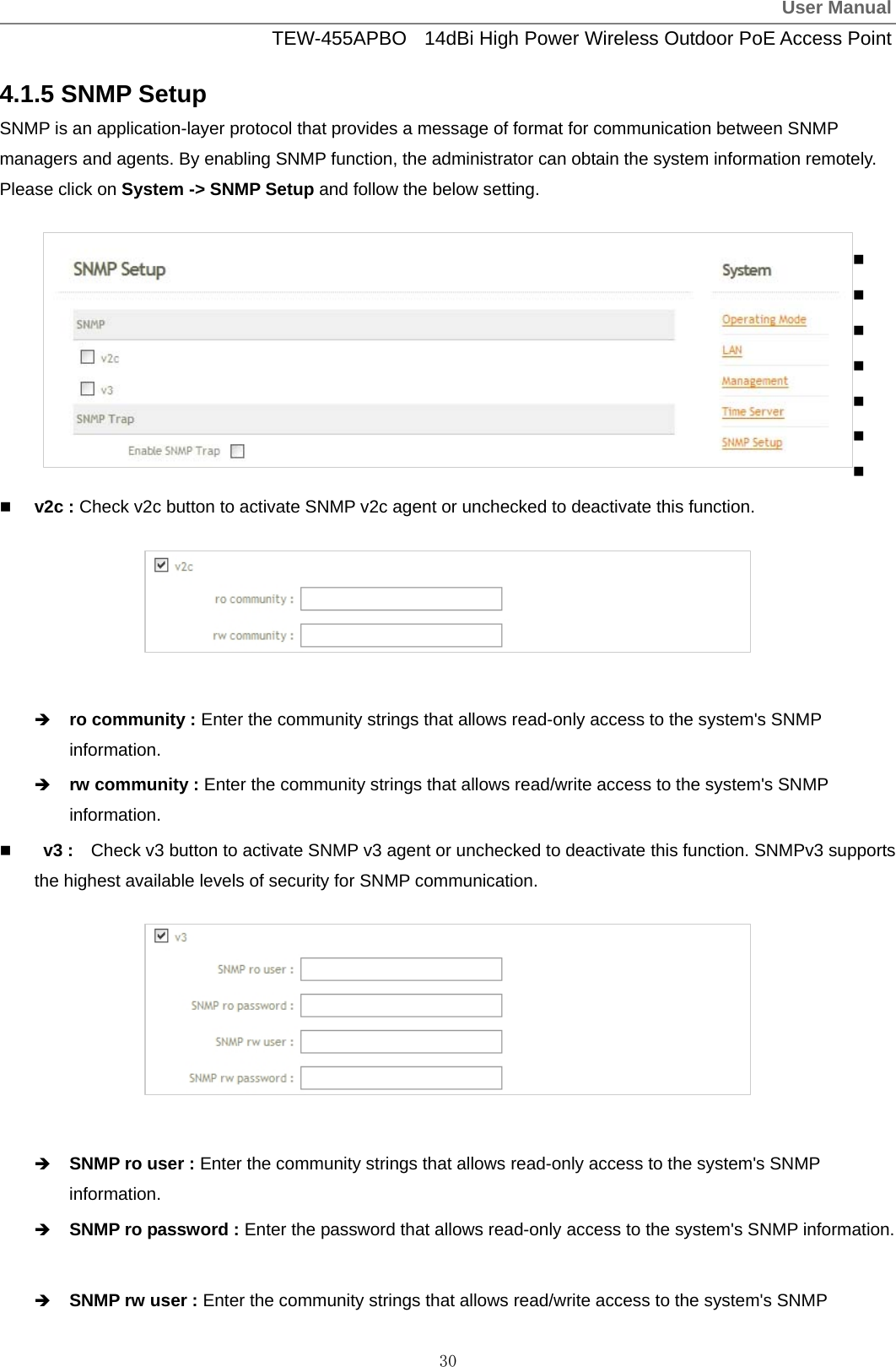
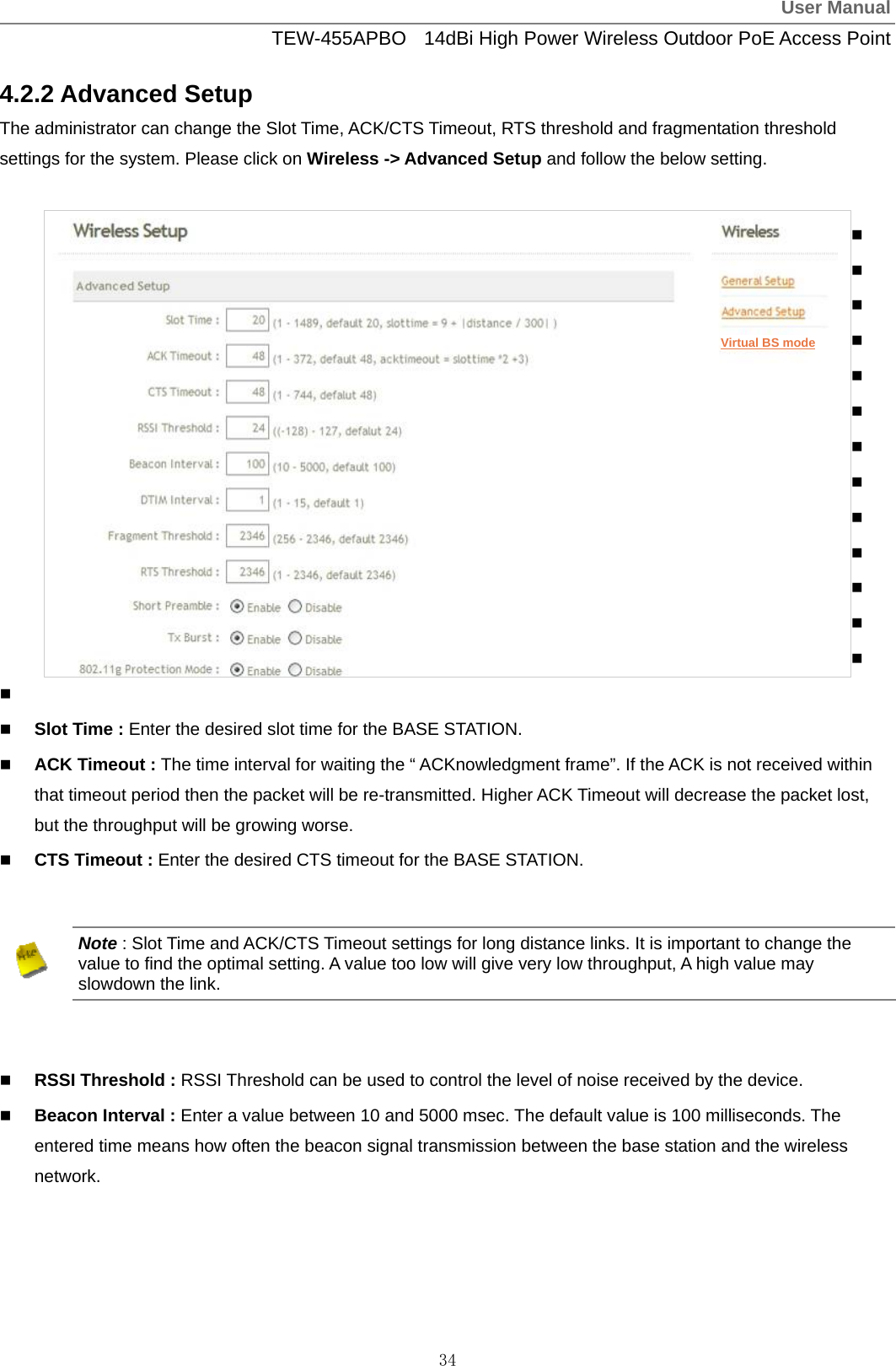
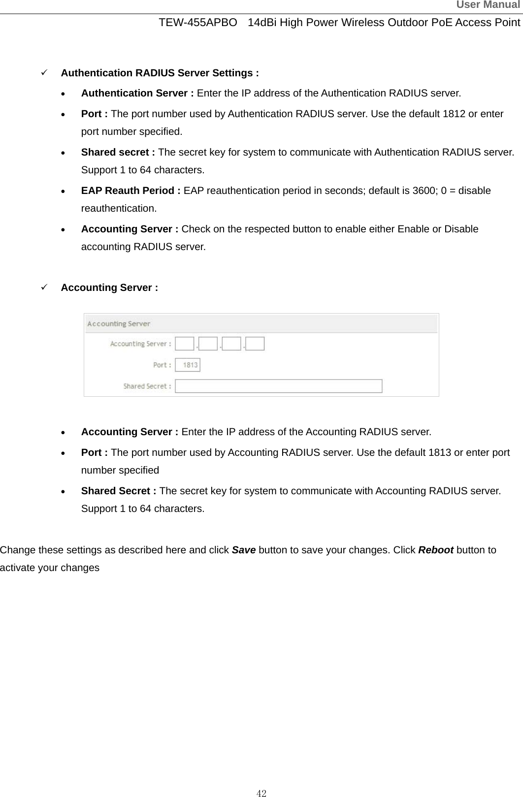
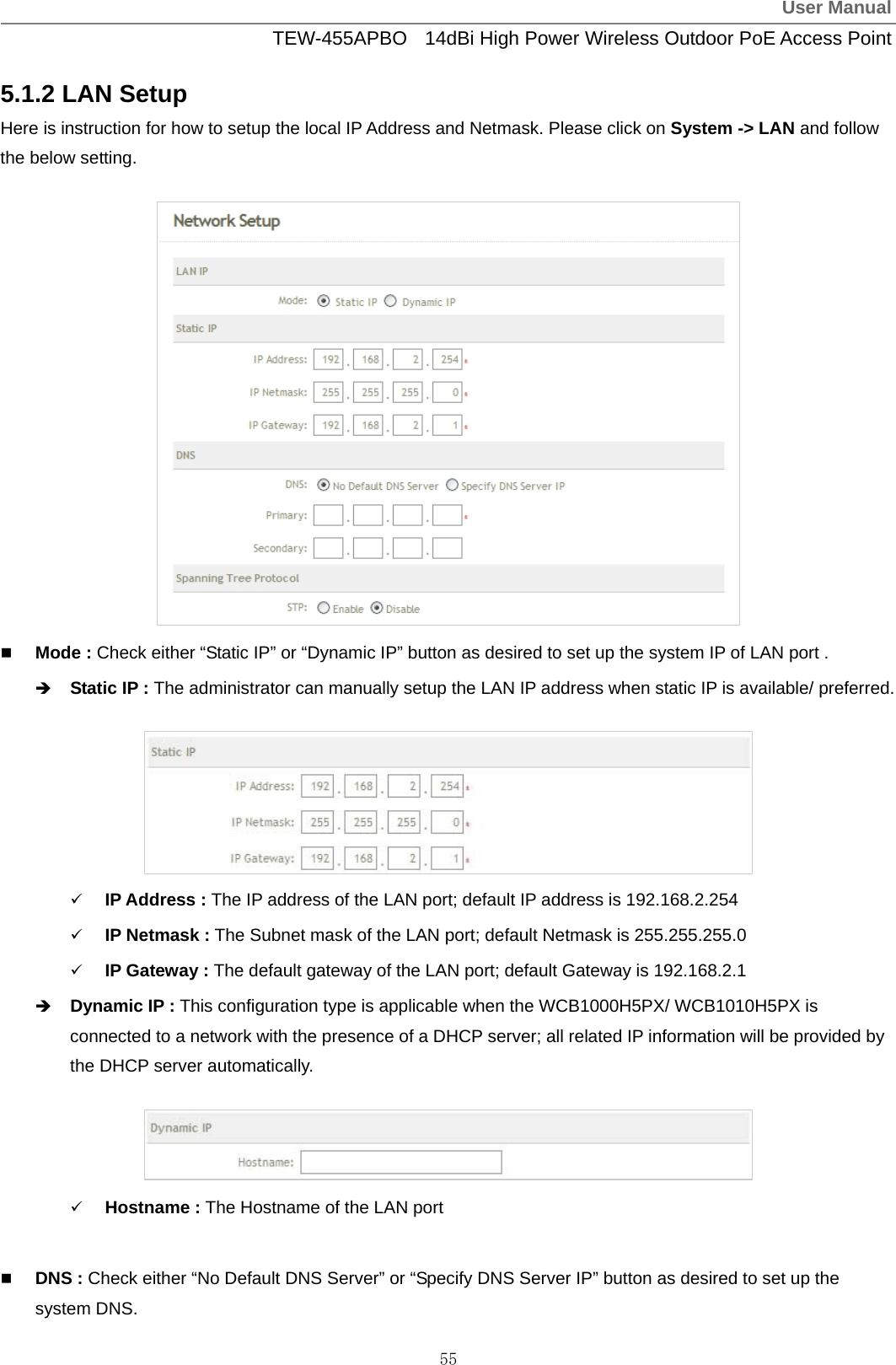
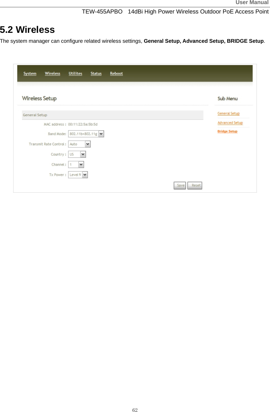
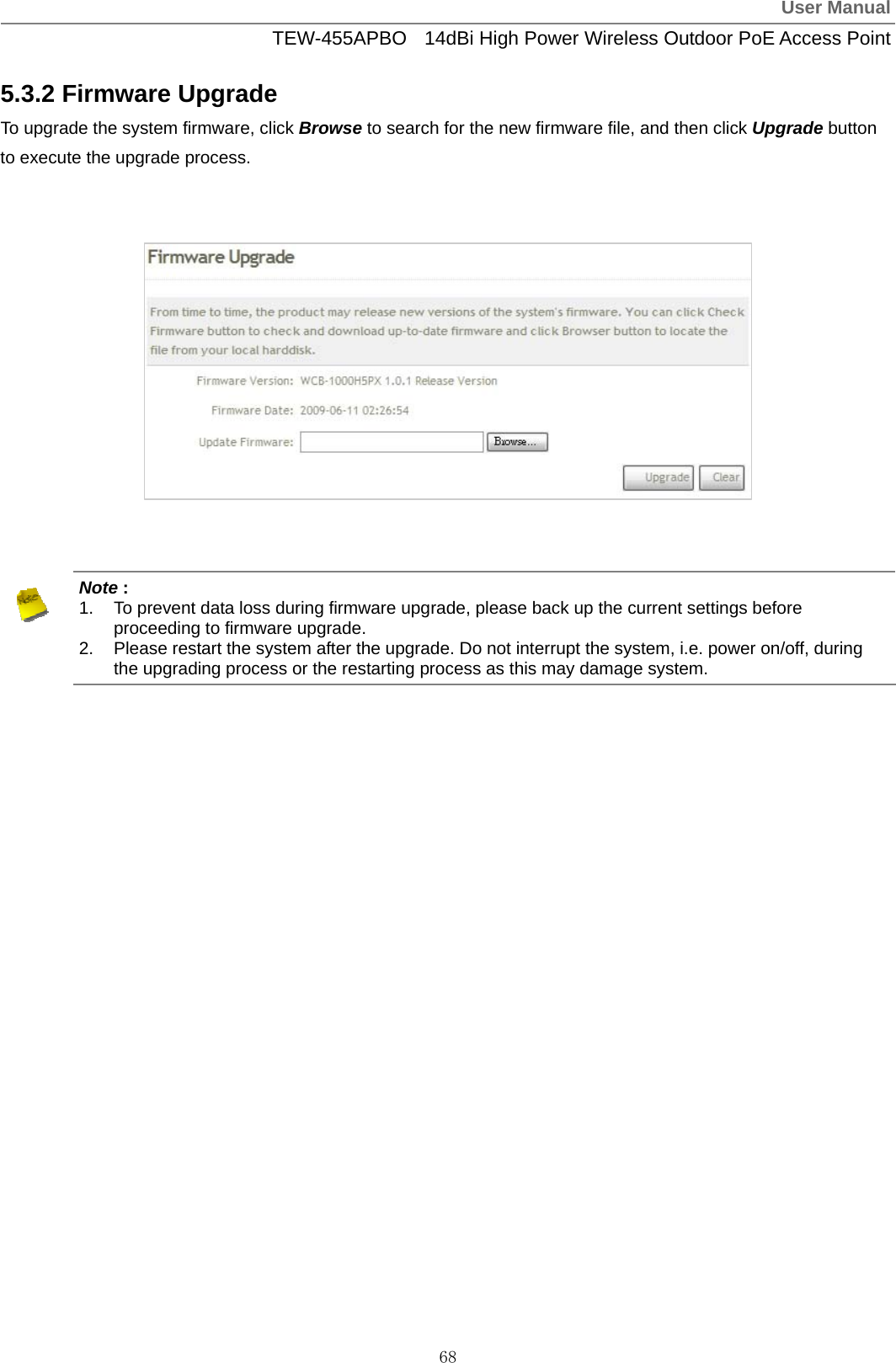
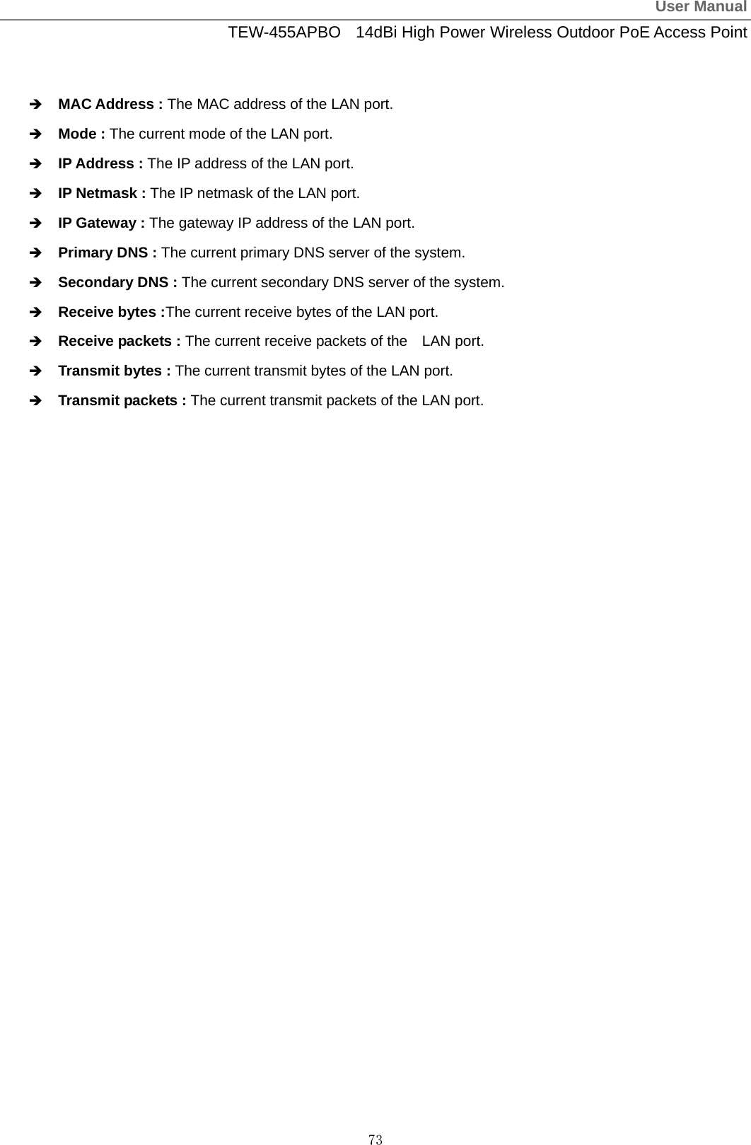
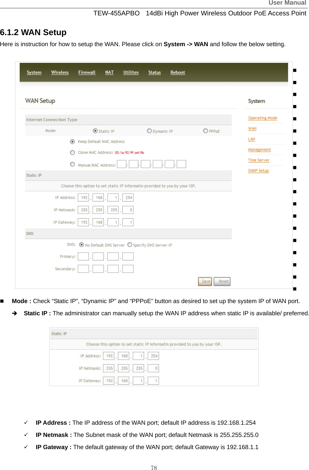
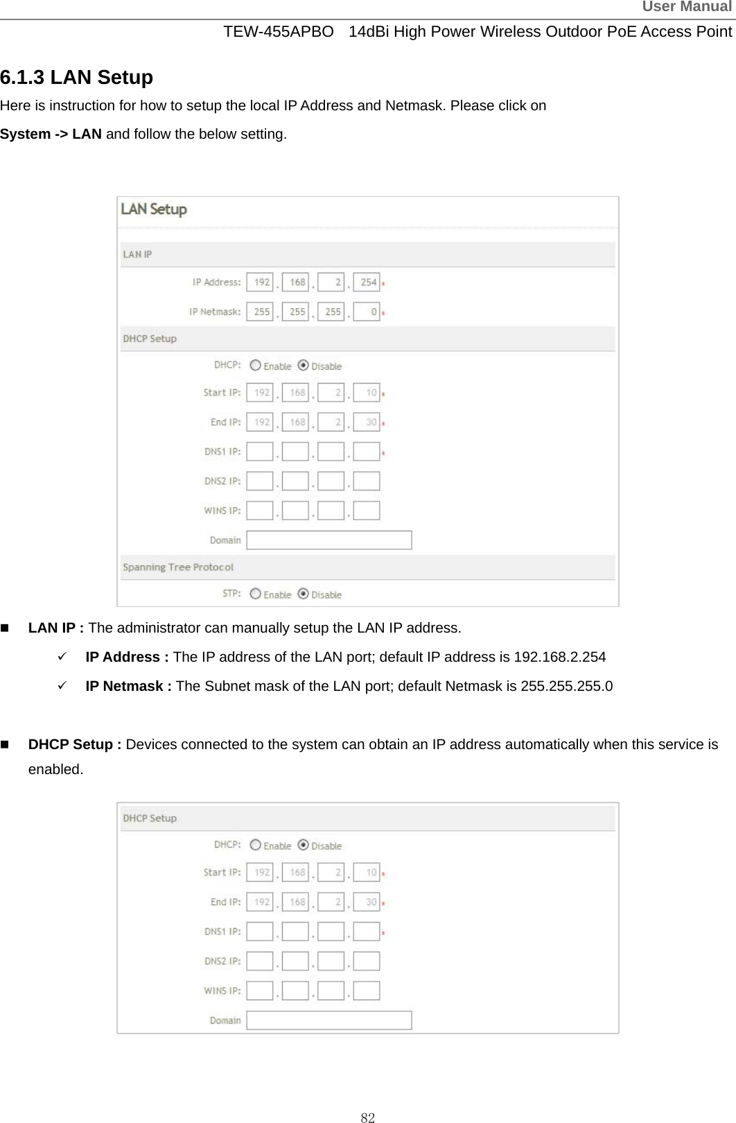
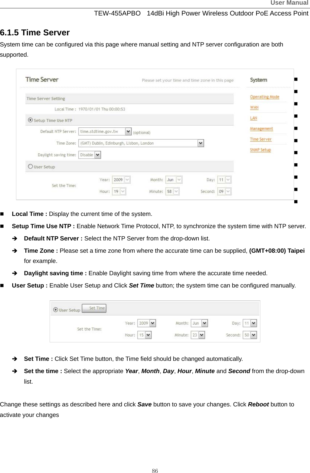
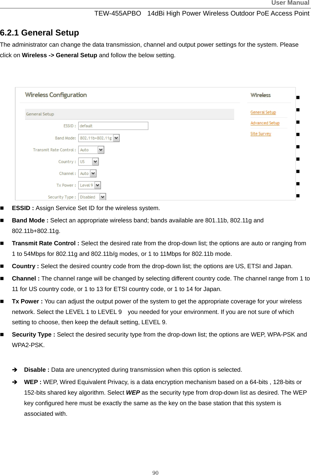
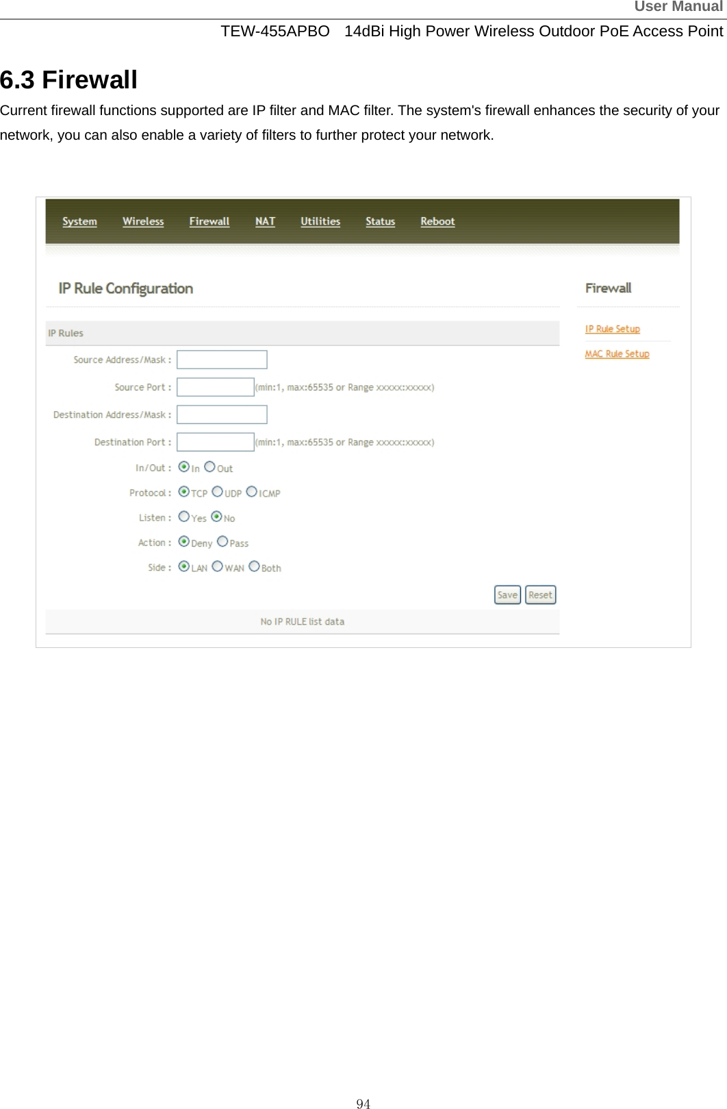
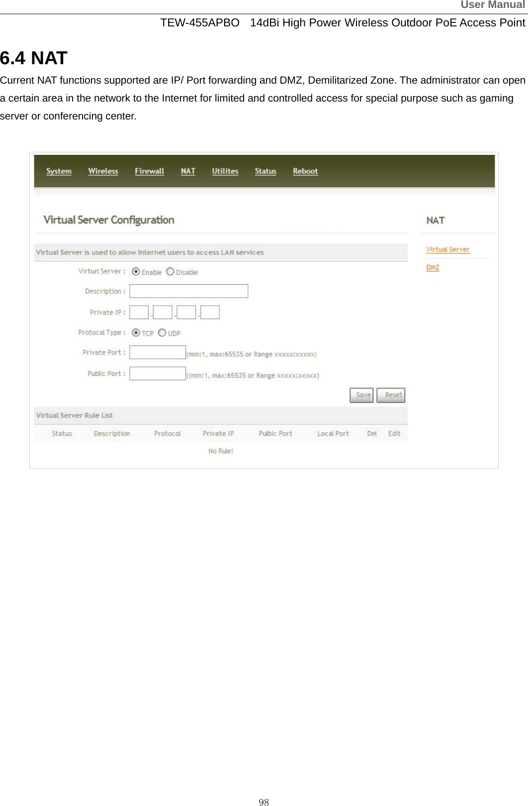
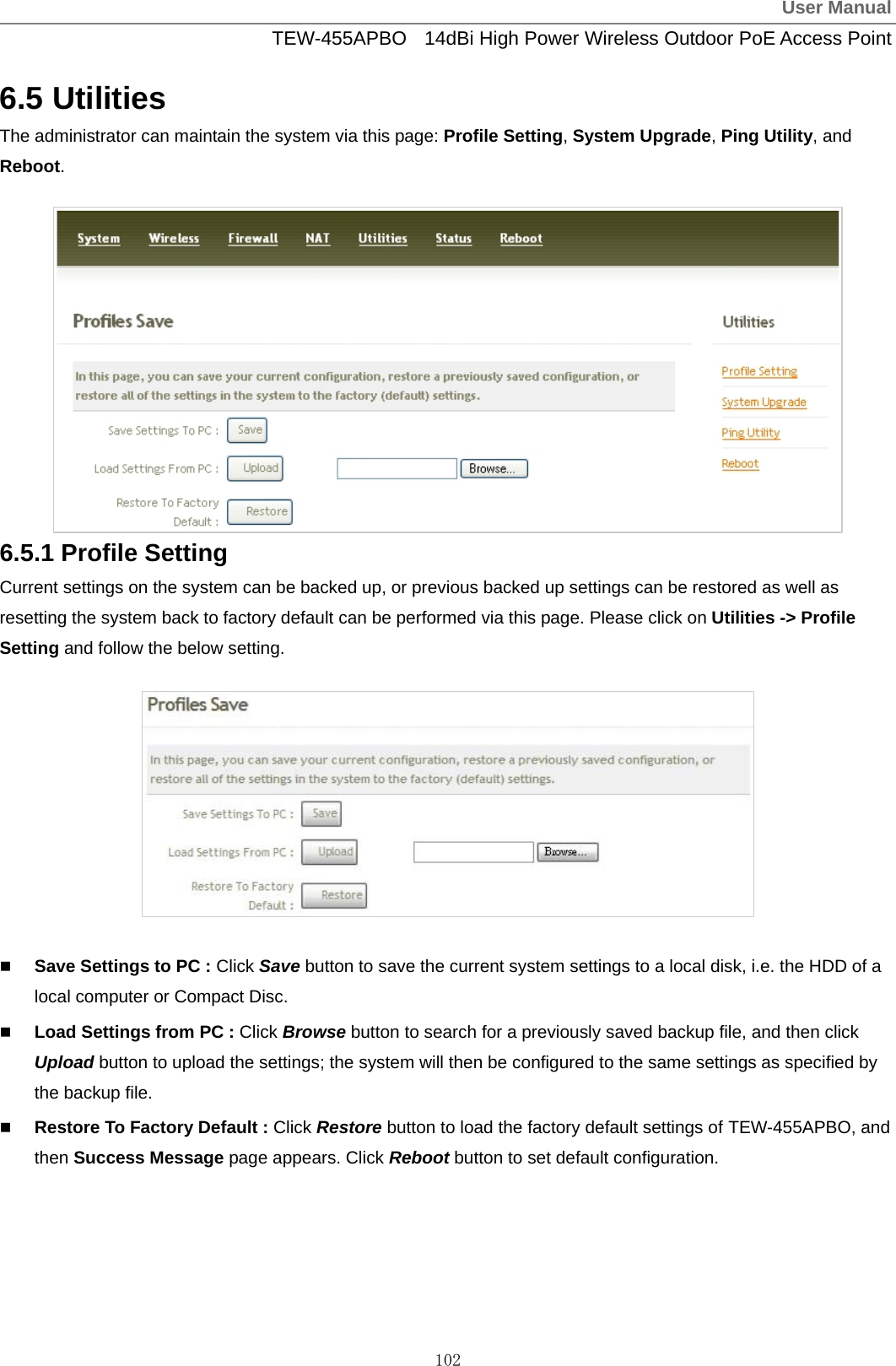
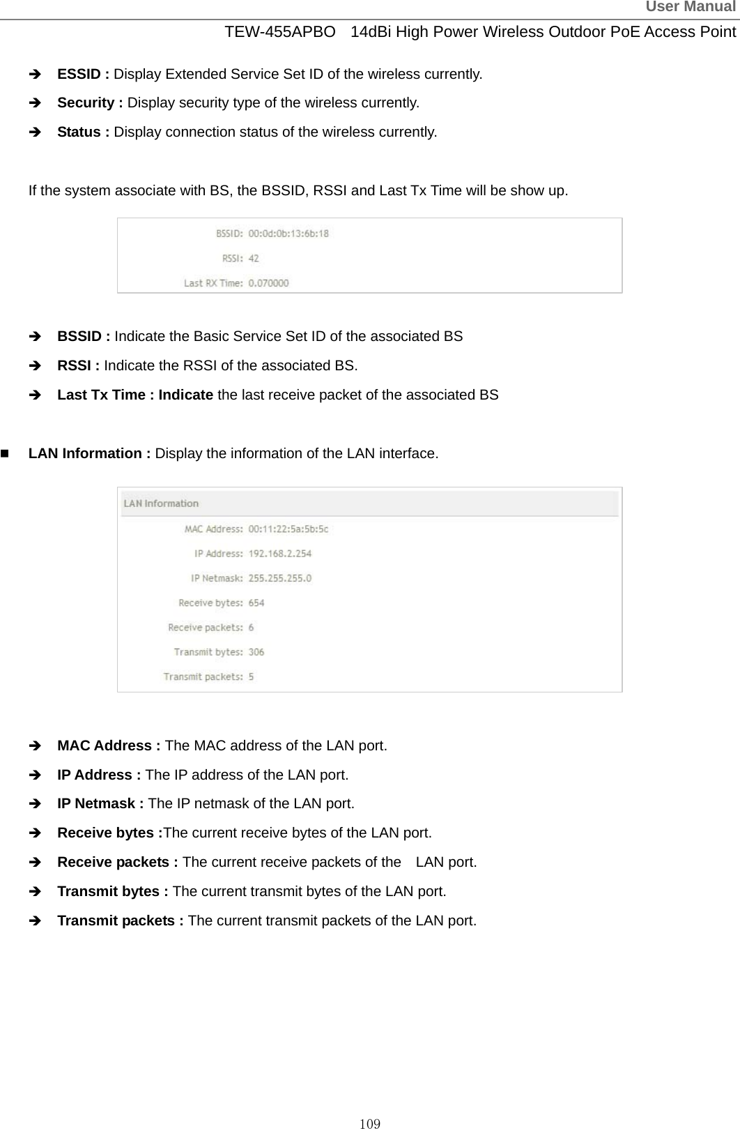
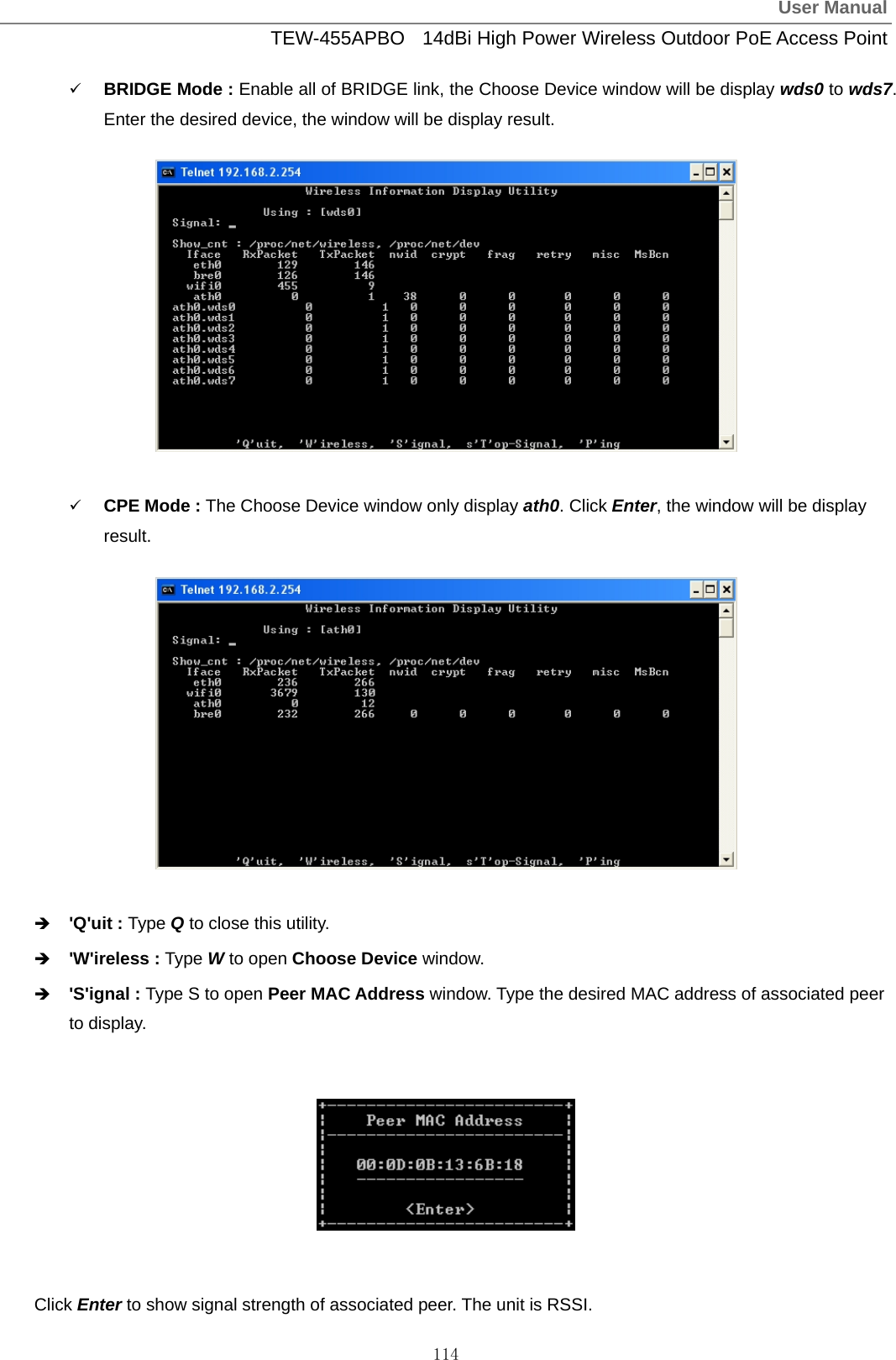
![User ManualTEW-455APBO 14dBi High Power Wireless Outdoor PoE Access Point 121 Table C Valid Characters for using WMI (continued) Block Field Valid Characters ESSID Length : 31 0-9, A-Z, a-z ~ ! @ # $ % ^ * ( ) _ + - { } | : < > ? [ ] / ; ` , . = Peer's MAC Address 12 HEX chars VLAN ID 1 ~ 4094 ; 0 is disable Description Length : 32 0-9, A-Z, a-z Space ~ ! @ # $ % ^ * ( ) _ + - { } | : < > ? [ ] / ; ` , . = BRIDGE Setup WEP Key 10, 26, 32 HEX chars Source Address IP Format; 1-254 Source Mask 0 ~ 32 Source Port 1 ~ 65535 Destination Address IP Format; 1-254 Destination Mask 0 ~ 32 IP Rule Setup Destination Port 1 ~ 65535 MAC Rule Setup MAC address MAC Format; 12 HEX chars Description Length : 32 0-9, A-Z, a-z space ~ ! @ # $ % ^ * ( ) _ + - { } | : < > ? [ ] / ; ` , . = Private IP IP Formate; 1-254 Private Port 1 ~ 65535 Virtual Server Public Port 1 ~ 65535 DMZ IP Address IP Format; 1-254](https://usermanual.wiki/TRENDNET/TEW455APBOV2/User-Guide-1253836-Page-124.png)