TRENDNET TEW455APBOV2 14dBi HIGH POWER WIRELESS OUTDOOR POE ACCESS POINT User Manual
TRENDNET, Inc. 14dBi HIGH POWER WIRELESS OUTDOOR POE ACCESS POINT Users Manual
TRENDNET >
Users Manual
TEW-455APBO
User Manual
V1.04
Table of Contents
Chapter 1. Before You Start ......................................................................................................... 1
1.1 Preface .................................................................................................................................. 1
1.2 Conventions........................................................................................................................... 1
Chapter 2. System Overview ....................................................................................................... 2
2.1 Introduction of TEW-455APBO .............................................................................................. 2
2.2 System Concept .................................................................................................................... 3
2.3 Product Benefit ...................................................................................................................... 4
2.4 Specification........................................................................................................................... 4
Chapter 3. Base Installation......................................................................................................... 7
3.1 Hardware Installation ............................................................................................................. 7
3.1.1 Package Contents............................................................................................................... 7
3.1.2 Panel Function Descriptions ...............................................................................................7
3.1.3 Hardware Installation Steps ................................................................................................ 9
3.2 Software Configuration ........................................................................................................ 10
3.2.1 Instruction to Web Management Interface ........................................................................ 10
3.2.2 Quick Configuration .......................................................................................................... 12
3.2.2.1 BASE STATION Mode (Point to Point)........................................................................... 12
3.2.2.2 BRIDGE Mode ............................................................................................................... 16
3.2.2.3 CPE Mode ..................................................................................................................... 19
Chapter 4. BASE STATION (Point to Point) Mode Configuration............................................... 23
4.1 System................................................................................................................................. 24
4.1.1 Operating Mode ................................................................................................................ 24
4.1.2 LAN Setup ........................................................................................................................ 25
4.1.3 Management..................................................................................................................... 27
4.1.4 Time Server ...................................................................................................................... 29
4.1.5 SNMP Setup ..................................................................................................................... 30
4.2 Wireless............................................................................................................................... 32
4.2.1 General Setup................................................................................................................... 33
4.2.2 Advanced Setup................................................................................................................ 34
4.2.3 Virtual BASE STATION Setup........................................................................................... 36
4.2.3.1 Virtual BASE STATION General Configuration .............................................................. 37
4.2.3.2 Virtual BS Access Control List (ACL) Setup................................................................... 43
4.3 Utilities ................................................................................................................................. 44
4.3.1 Profile Setting ................................................................................................................... 44
4.3.2 Firmware Upgrade ............................................................................................................ 45
4.3.3 Ping Utility......................................................................................................................... 46
4.3.4 Reboot .............................................................................................................................. 47
4.4 Status................................................................................................................................... 48
4.4.1 Overview........................................................................................................................... 49
4.4.2 Client................................................................................................................................. 51
4.4.3 Event Log.......................................................................................................................... 52
Chapter 5. BRIDGE Mode Configuration ................................................................................... 53
5.1 System................................................................................................................................. 54
5.1.1 Operating Mode ................................................................................................................ 54
5.1.2 LAN Setup ........................................................................................................................ 55
5.1.3 Management..................................................................................................................... 57
5.1.4 Time Server ...................................................................................................................... 59
5.1.5 SNMP Setup ..................................................................................................................... 60
5.2 Wireless............................................................................................................................... 62
5.2.1 General Setup................................................................................................................... 63
5.2.2 Advanced Setup................................................................................................................ 64
5.2.3 BRIDGE Setup.................................................................................................................. 66
5.3 Utilities ................................................................................................................................. 67
5.3.1 Profile Setting ................................................................................................................... 67
5.3.2 Firmware Upgrade ............................................................................................................ 68
5.3.3 Ping Utility......................................................................................................................... 69
5.3.4 Reboot .............................................................................................................................. 70
5.4 Status................................................................................................................................... 71
5.4.1 Overview........................................................................................................................... 72
5.4.2 BRIDGE List ..................................................................................................................... 74
5.4.3 Event Log.......................................................................................................................... 75
Chapter 6. CPE Mode Configuration ......................................................................................... 76
6.1 System................................................................................................................................. 77
6.1.1 Operating Mode ................................................................................................................ 77
6.1.2 WAN Setup ....................................................................................................................... 78
6.1.3 LAN Setup ........................................................................................................................ 82
6.1.4 Management..................................................................................................................... 84
6.1.5 Time Server ...................................................................................................................... 86
6.1.6 SNMP Setup ..................................................................................................................... 87
6.2 Wireless............................................................................................................................... 89
6.2.1 General Setup................................................................................................................... 90
6.2.2 Advanced Setup................................................................................................................ 92
6.2.3 Site Survey ....................................................................................................................... 93
6.3 Firewall ................................................................................................................................ 94
6.3.1 IP Rule Setup.................................................................................................................... 95
6.3.2 MAC Rule Setup ............................................................................................................... 97
6.4 NAT...................................................................................................................................... 98
6.4.1 Virtual Server (IP/ Port Forwarding).................................................................................. 99
6.4.2 DMZ................................................................................................................................ 101
6.5 Utilities ............................................................................................................................... 102
6.5.1 Profile Setting ................................................................................................................. 102
6.5.2 Firmware Upgrade ..........................................................................................................103
6.5.3 Ping Utility....................................................................................................................... 104
6.5.4 Reboot ............................................................................................................................ 105
6.6 Status................................................................................................................................. 106
6.6.1 Overview......................................................................................................................... 107
6.6.2 DHCP Clients...................................................................................................................110
6.6.3 Event Log.........................................................................................................................111
7. Command Line Interface(CLI)...............................................................................................112
7.1 Accessing the CLI with Telnet .............................................................................................112
7.2 Using the CLI ......................................................................................................................113
Appendix A. Windows TCP/IP Settings ................................................................................116
Appendix B. Valid Characters when using WMI....................................................................118
Appendix D. All Antenna type for Products.......................................................................... 122
.

User Manual
TEW-455APBO 14dBi High Power Wireless Outdoor PoE Access Point
1
Chapter 1. Before You Start
1.1 Preface
The 802.11 b/g compliant TEW-455APBO is an outdoor wireless device that can be used for three purposes. It can
be deployed as a fixed Point to Point wireless base station between buildings, a bridge between LAN and wireless
base station, or it can be used as a fixed wireless point to point between CPE and Internet Service Provider.
The die-cast sealed TEW-455APBO is compact in size and weatherproof. It comes with a mounting kit, for pole or
wall mount. It is suitable for both indoor and outdoor usage with its 500mW output power, which is higher than a
typical indoor base station (100mW).
This User’s Manual provides instructions and reference material for getting started with TEW-455APBO. This guide
will also show you how to connect TEW-455APBO to other network devices.
1.2 Conventions
Conventions used in the system are :
Î Save : Save settings by clicking this button
Î Reset : Clear settings by clicking this button
Î Reboot : Activate and reboot system settings by clicking this button
Î * : Indicate information in the related field is required
Conventions used in this manual :
Î Warning : Indicates a caution or warning message to inform users something might damage the system
Î Note : Indicates information that the users shall pay attention to.

User Manual
TEW-455APBO 14dBi High Power Wireless Outdoor PoE Access Point
2
Chapter 2. System Overview
2.1 Introduction of TEW-455APBO
The 802.11 b/g compliant TEW-455APBO is an outdoor wireless device that can be used for three purposes. It can
be deployed as a outdoor fixed point to point between two building or between a building and wireless base station,
or The fixed wireless point to point between CPE and Internet Service Provider.
The die-cast sealed TEW-455APBO is compact in size and weatherproof. It comes with a mounting kit, for pole or
wall mount. It is suitable for both indoor and outdoor usage with its 500mW output power, which is higher than a
typical indoor BS (100mW).
User Manual
TEW-455APBO 14dBi High Power Wireless Outdoor PoE Access Point
3
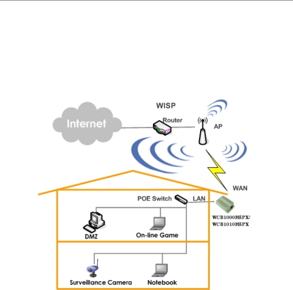
2.2 System Concept
The TEW-455APBO can be used in many applications with examples as follows:
The Fixed point to point operation (connection between a building and a wireless base station).
Bridge between LAN and wireless base station.
The Fixed wireless point to point between CPE and Internet Service Provider.
Note: The device shall be mounted on permanent structures.

User Manual
TEW-455APBO 14dBi High Power Wireless Outdoor PoE Access Point
4
2.3 Product Benefit
500mW at 2.4GHz Output Power
Topology : Point to Point;
Operation Modes : Base station mode(Only point to point), Bridge mode (Bridge), CPE mode(Client Bridge)
Multiple ESSIDs Capability
VLAN tag over BRIDGE
Supporting Qos & 802e WMM
Business-class WLAN Security & Client Authentications
Support 3 LEDs Wireless Signal Strength
2.4 Specification
Wireless and Wired Interface Standard
Î Wireless :
1. IEEE 802.11g (Up to 54Mbps)
2. IEEE 802.11b (Up to 11Mbps)
Î Ethernet : 1 x IEEE 802.3 and IEEE 802.3u
Wireless Radio
Î Frequency band : 2.4GHz
Î Modulations :
1. 802.11b : DSSS (CCK, DQPSK, DBPSK)
2. 802.11g : OFDM (64-QAM, 16-QAM, QPSK, BPSK)
Î Channels :
1. USA (Channel 1~11)
2. Japan (Channel 1~14)
3. Europe (Channel 1~13)
Î Data Rate with auto fallback : 54, 48, 36, 24, 18, 12, 11, 9, 6, 5.5, 2 and 1 Mbps
Î Receiver Sensitivity :
1. 802.11b : 11Mbps@-89dBm
2. 802.11g : 54Mbps@-74dBm
Î RF transmission power : 27dBm /500mW (
Î WCB1000H5PX provides a N-Female reverse connector.
WCB1010H5PX built-in 12.8dBi at 2.4GHz Sector Directional Antenna (Horizontal : 110 degree, Vertical : 60
degree)

User Manual
TEW-455APBO 14dBi High Power Wireless Outdoor PoE Access Point
5
General Base Station Features
Î Number of ESSID : 8
Î Three mode : BASE STATION P to P Mode, BRIDGE Mode and CPE Mode
Î Slot Time, ACK/CTS Timeout support
Î RSSI threshold support
Î TX burst support
Î Beacon interval : adjustable to best adapt to the deployment environment
Î IBSP : to facilitate faster roaming for the stations among different BASE STATION nearby
Î 802.11g protection : to let the transmission rate of the associated 802.11g stations not to be affected with
surrounding existence of 802.11b stations
Î RTS and fragmentation control
Î Adjustable transmission power : 9 Levels (*Note)
Î Wireless site survey : for scanning the surrounding base stations for connection
Î VLAN tag support
Gateway Features in the CPE Mode
Î Built-in NAT mode : to support IP sharing on the LAN side for multiple users(subscribers) to get access to the
Internet
Î Built-in DHCP server for issuing local IP addresses
Î Built-in DNS client
Î IP/ Port forwarding and DMZ
Î IP/ MAC rule filtering
Security
Î Data encryption : WEP (64/128/152-bits), WPA/WPA2 with TKIP or AES-CCMP
Î User Authentication : WEP, IEEE 802.1X, WPA-PSK, WPA-Enterprise, MAC ACL
Î Setting for TKIP/ CCMP/AES key's refreshing period
Î Support IEEE 802.11 mixed mode; open and shared key authentication
Î Hidden ESSID : broadcast SSID option can be turned off to prevent SSID broadcast to the public
Î Station Isolation setting : when enabled, all stations associated with this BASE STATION can not
communicate with each other
Î Support data encryption over BRIDGE link
Note: The Power Level only can be adjusted lower than default 9 Level. Each Level is 3dBm lower from default
maximum output power. The default output Power for each channel is in the bellowed table.
Channel Channel 1 Channel 2~10 Channel 11
Fixed Maximum Output Power 18.34 dBm 26.85 dBm 16.77 dBm

User Manual
TEW-455APBO 14dBi High Power Wireless Outdoor PoE Access Point
6
Administration
Î Web-based management interface
Î Remote configuration and management
Î Remote firmware upgradeable
Î Software one-button-click to reset back to factory defaults
Î Utilities for system configuration backup and restoration
Î SNMP MIBII support (v2c/ v3)
Î NTP time synchronization
Î Syslog client
Î Support Event Log
Î Support statistics on total transmission encountered and transmitting error occurred
Hardware Specifications
Î Die cast case : weather proof, compliant with IP67 standard
Î On board surge protection
Î LED Indication : Power x 1; Ethernet x 1; Wireless x 1; Signal Strength x 3
Physical and Power
Î PoE : DC 48V/ 0.4 A
Î Form factor : Wall or Pole Mountable
Î Dimensions (W x D x H) : 6.5” x 3.8” x 1.9” (165 x 96 x 48 mm)
Î Weight: 15.9 lbs (7.2 kg)
Environment
Î Operation temperature : -30℃ ~ 60℃
Î Storage temperature : -30℃ ~ 85℃
Î Operation humidity : 100% maximum (Non-condensing)
Î Storage humidity : 100% (Non-condensing)
Standard Pack Accessories
Î PSE : Power Sourcing Equipment x 1
Î AC Cable x 1
Î Mounting Kit x 1
User Manual
TEW-455APBO 14dBi High Power Wireless Outdoor PoE Access Point
7
Chapter 3. Base Installation
3.1 Hardware Installation
3.1.1 Package Contents
The standard package contents of TEW-455APBO :
TEW-455APBO x 1
Quick Installation Guide x 1
CD-ROM (with User Manual and QIG) x 1
PSE with AC Cable x 1
Mounting Kit x 1
Warning : It is highly recommended to use all the supplies in the package instead of substituting any
components by other suppliers to guarantee best performance.
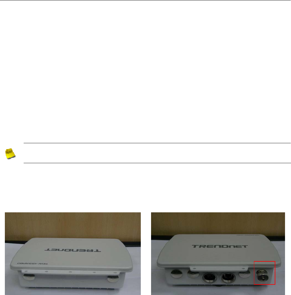
3.1.2 Panel Function Descriptions
TEW-455APBO
Front Panel Rear Panel
1. Reset Button : System reboot button press until LED flashed and release for system
reboot or for reset to factory default press, LED flashes keep pressing
until LED becomes static
2. Power : Red LED ON indicates power on, and OFF indicates power off
3. Signal Strength : Yellow LED ON indicates Low Signal (CPE Mode)
4. Signal Strength : Green LED ON indicates Normal Signal (CPE Mode) or (BRIDGE Mode
Only)
5. Signal Strength : Green LED ON indicates High Signal (CPE Mode) or (BASE STATION
Mode Only)
6. WLAN : Green LED FLASH indicates Wireless ON, and FLASH quickly indicates
9

User Manual
TEW-455APBO 14dBi High Power Wireless Outdoor PoE Access Point
8
Wireless Transmit quickly.
7. Ethernet : Green LED ON indicates connection, OFF indicates no connection
8. PoE Connector : For connecting to PSE
9. N-Type reverse Connector : For connecting to N-Type Female reverse connector
Note :
In CEP Mode, the LED 3 ON indicates the signal Low ( Signal <= 10 RSSI); the LED 3 and 4 ON
indicate the signal Normal (10 < Signal <=40 RSSI); the LED 3, 4 and 5 ON indicate the signal High
( Signal > 40 ).
Only LED 4 ON indicates the operating mode is BRIDGE Mode; only LED 5 ON indicates the operating
mode is BASE STATION Mode.
User Manual
TEW-455APBO 14dBi High Power Wireless Outdoor PoE Access Point
9
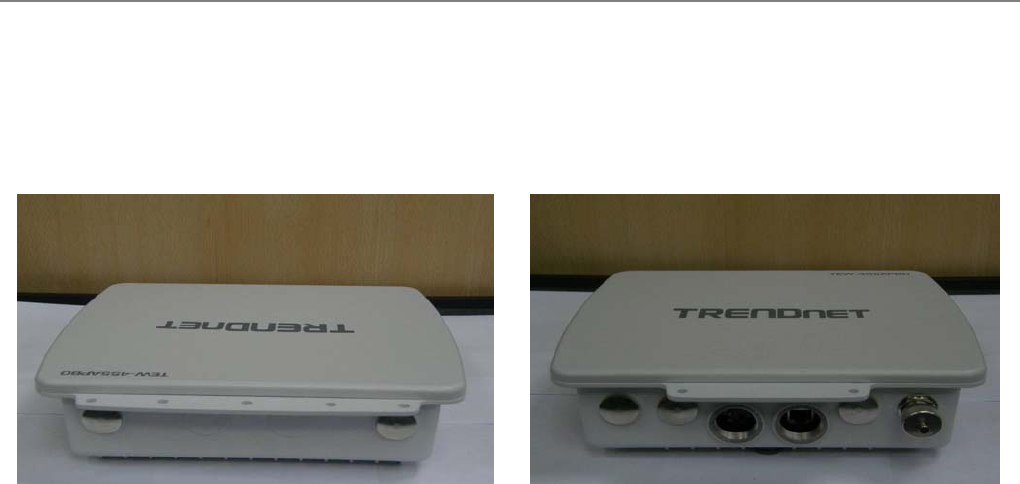
3.1.3 Hardware Installation Steps
Please follow the steps mentioned below to install the hardware of TEW-455APBO:
Front Panel Rear Panel
1. Connect N-type reverse antenna to the N-type reverse connector on the rear panel.
2. Connect PSE to the PoE connector on the front panel.
3. Connect an Ethernet cable to the PSE and the other end to a computer.
4. Power on the PSE in order to supply power to TEW-455APBO

User Manual
TEW-455APBO 14dBi High Power Wireless Outdoor PoE Access Point
10
3.2 Software Configuration
3.2.1 Instruction to Web Management Interface
TEW-455APBO supports web-based configuration. Upon the completion of hardware installation, TEW-455APBO
can be configured through a PC/NB by using its web browser such as Internet Explorer version 6.0.
Default IP Address : 192.168.2.254
Default IP Netmask : 255.255.255.0
Default User Name and Password : admin / default
Step
IP Segment Set-up for Administrator's PC/NB
Set the IP segment of the administrator's computer to be in the same range as TEW-455APBO for accessing
the system. Do not duplicate the IP Address used here with IP Address of TEW-455APBO or any other device
within the network
Example of Segment :
The value for underlined area can be changed as desired; the valid range is 1 ~ 254. However, 254 shall be
avoided as it is already used by TEW-455APBO; use 10 as an example here.
Î IP Address : 192.168.2.10
Î IP Netmask : 255.255.255.0
Launch Web Browser
Launch as web browser to access the web management interface of system by entering the default IP Address,
http://192.168.2.254, in the URL field, and then press Enter.
User Manual
TEW-455APBO 14dBi High Power Wireless Outdoor PoE Access Point
11
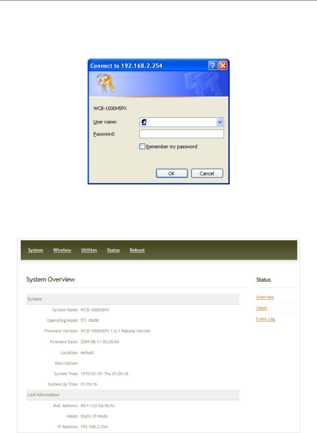
System Login
The system manager Login Page then appears.
Enter “admin” as User name and “default” as Password, and then click OK to login to the system.
Login Success
System Overview page will appear after successful login.
User Manual
TEW-455APBO 14dBi High Power Wireless Outdoor PoE Access Point
12
3.2.2 Quick Configuration
TEW-455APBO is a three mode system which can be configured either as a gateway or an base station as desired.
This section provides a step-by-step configuration procedure for basic installation of BASE STATION Mode,
BRIDGE Mode and CPE Mode.
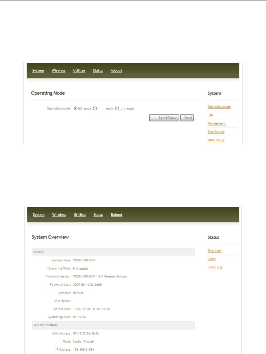
3.2.2.1 BASE STATION Mode (Point to Point)
Step 1 : Mode Confirmation
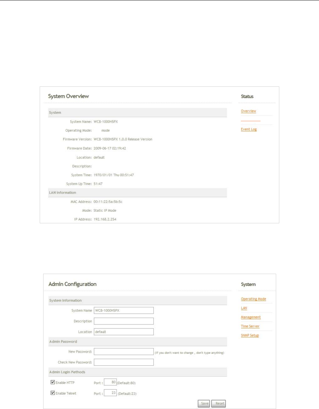
Ensure the Operating Mode is currently at BASE STATION mode; the web management UI can be viewed at
the Status section under the System Overview page.
B
User Manual
TEW-455APBO 14dBi High Power Wireless Outdoor PoE Access Point
13
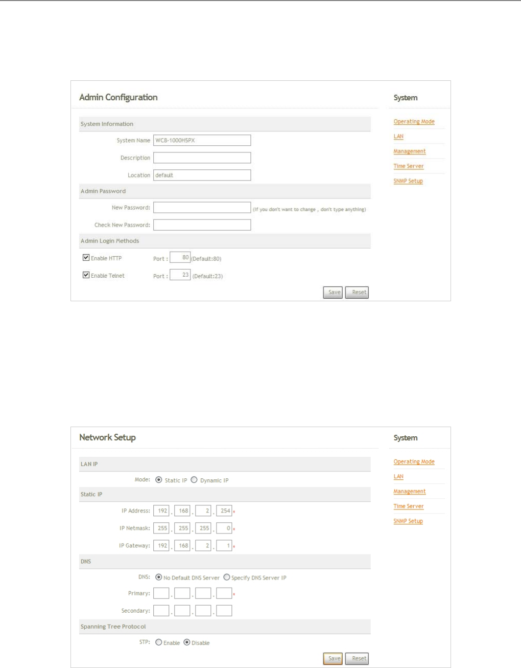
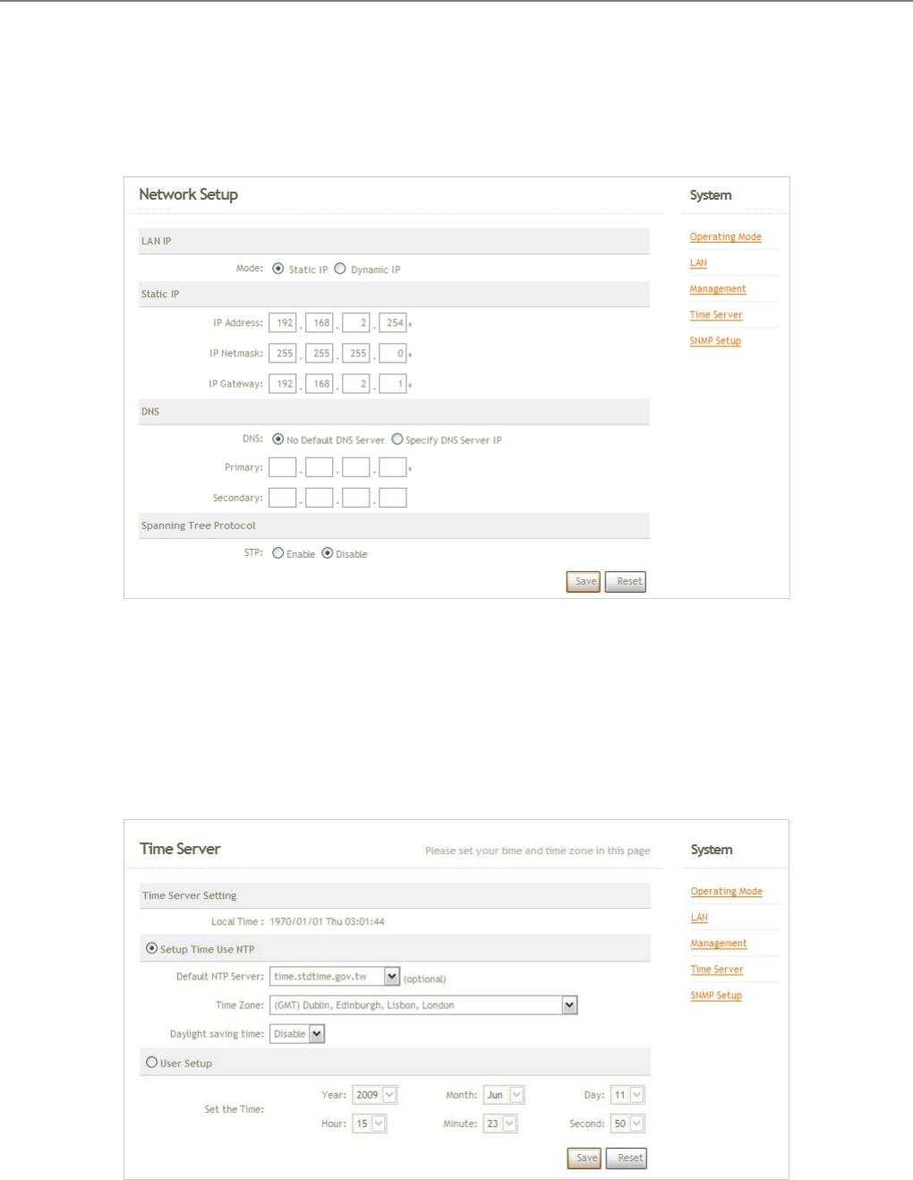
Step 2 : Change Password
Click System -> Management and then Admin Configuration page appears.
Enter a new password, and verify it again in the New Password and Check New Password field respectively.
Click Save button, and process with steps followed.
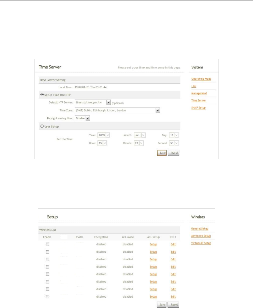
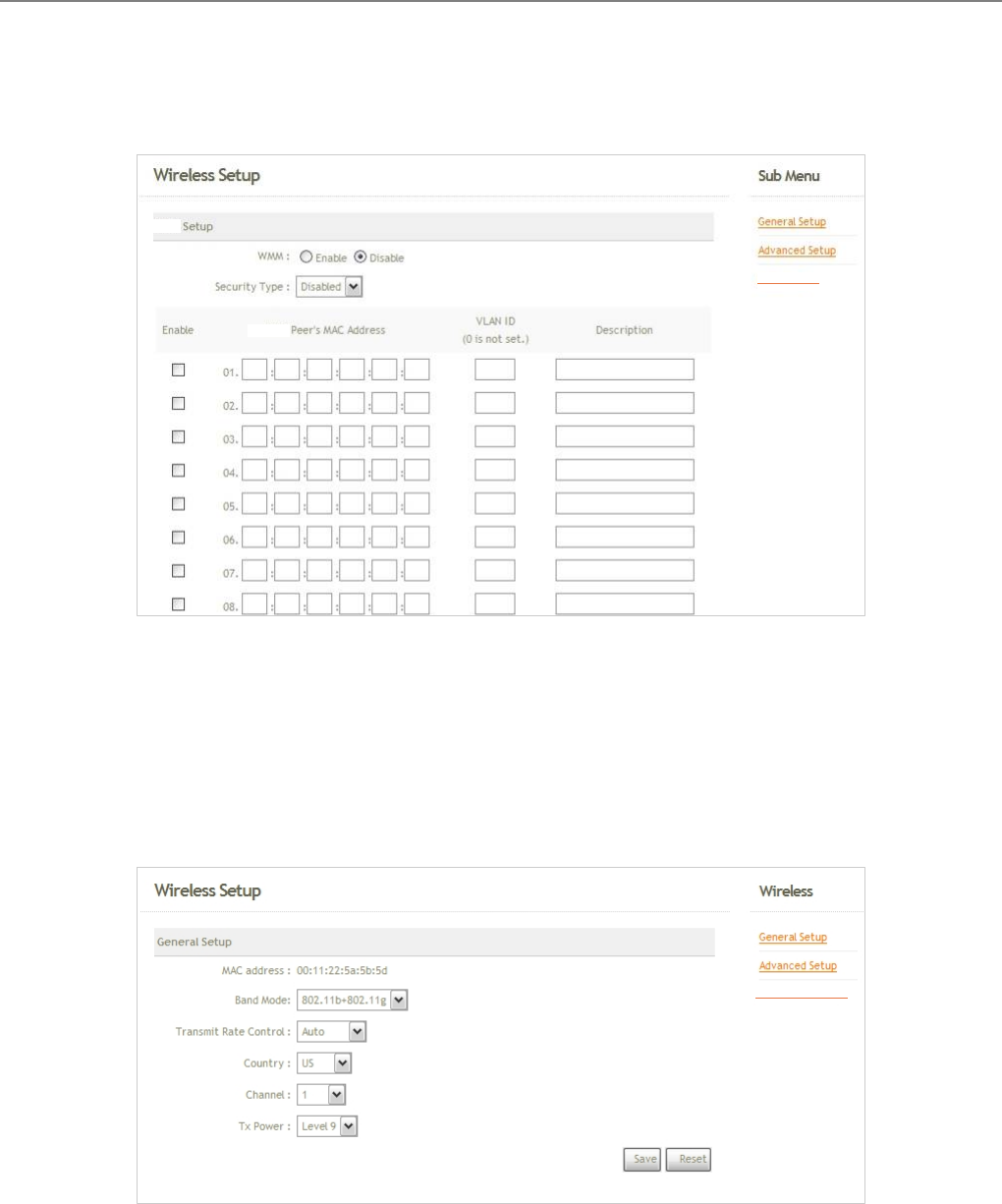
Step 3 : LAN IP Settings
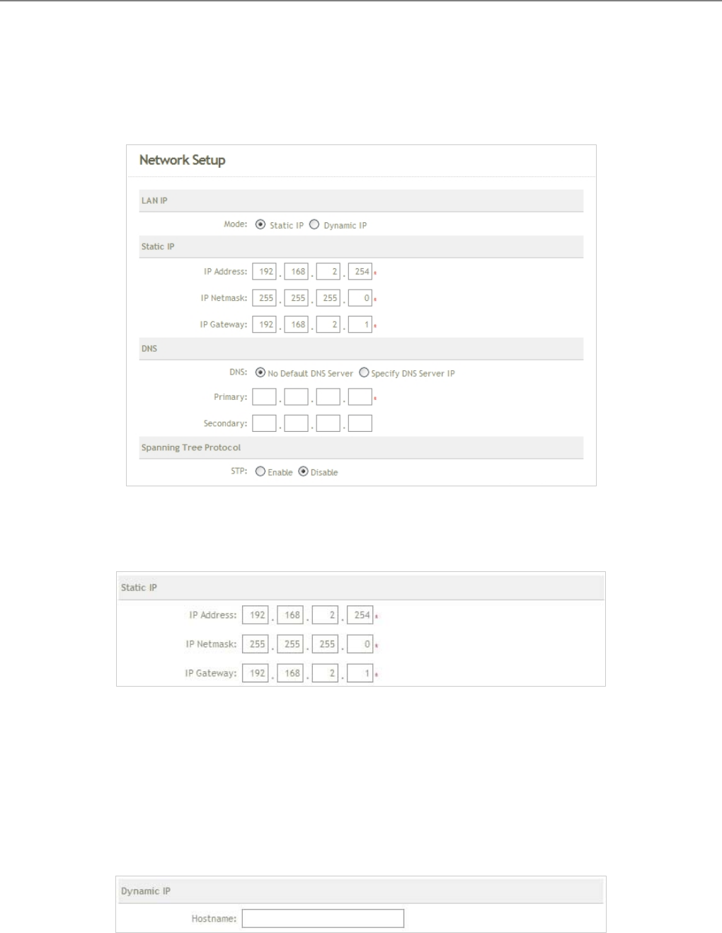
Click System -> LAN, and then Network Setup page appears.
Enable “Static IP” and “DNS”, and enter the related information in the field marked with red asterisks. Click
Save button to save the settings.
User Manual
TEW-455APBO 14dBi High Power Wireless Outdoor PoE Access Point
14
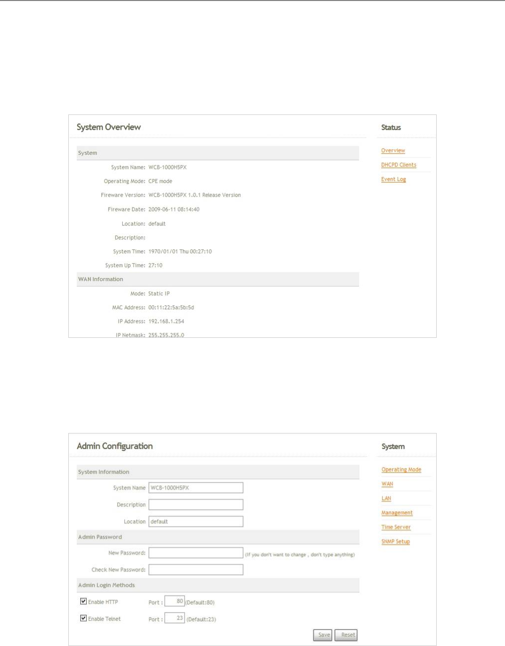
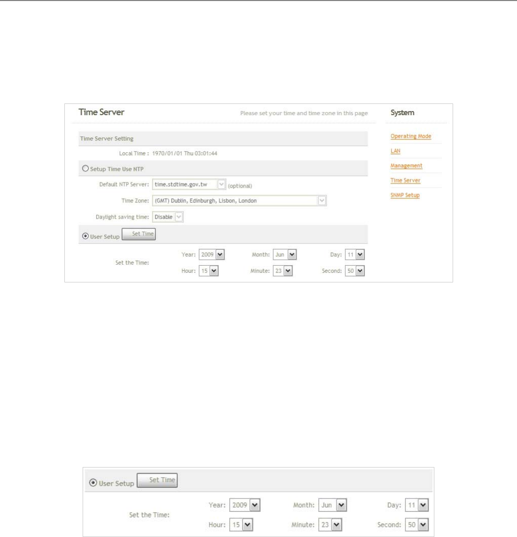
Step 4 : Time Zone settings
Click System -> Time Server, and then Time Server Setup page appears.
Enable “Setup Time Use NTP”, and then enter the related information. Click Save button to save the settings.
Step 5 : ESSID Settings
Click Wireless -> Virtual BASE STATION Setup, and then VBS Setup page appears.
Enable “VBS0”, and then click Save button to save settings. Click “Edit” and then VBS0 Configuration page
appears.
VBS
VBS
VBS 0
V
BS 1
VBS 2
VBS
VBS 4
VBS 3
VBS 6
VBS 5
V
BS 7
BS00
BS01
BS02
BS03
BS04
BS05
BS06
BS07
User Manual
TEW-455APBO 14dBi High Power Wireless Outdoor PoE Access Point
15
Setup broadcast ESSID for easy identification of system when device is trying to associate with service. Click
Save button to save settings
Step 6 : Security Settings
In VBS0 Configuration page, select WEP in “Security Type“ pull down menu. The WEP setting field will show
up immediately.
Enter the WEP key information required in the WEP settings field, and the same information will also be used
to set up devices which will then be using TEW-455APBO's services.
Click Reboot to activate all settings configured so far.
Congratulation !
The BASE STATION mode is now successfully configured.
BS00
VBS
User Manual
TEW-455APBO 14dBi High Power Wireless Outdoor PoE Access Point
16
3.2.2.2 BRIDGE Mode
Step 1 : Mode Confirmation
Ensure the Operating Mode is currently at BRIDGE mode; the web management UI can be viewed at the
Status section under the System Overview page.
Step 2 : Change Password
Click System -> Management and then Admin Configuration page appears.
Enter a new password, and verify it again in the New Password and Check New Password field respectively.
Click Save button, and process with steps followed.
B
Bridge List
User Manual
TEW-455APBO 14dBi High Power Wireless Outdoor PoE Access Point
17
Step 3 : LAN IP Settings
Click System -> LAN, and then Network Setup page appears.
Enable “Static IP” and “DNS”, and enter the related information in the field marked with red asterisks. Click
Save button to save the settings.
Step 4 : Time Zone settings
Click System -> Time Server, and then Time Server Setup page appears.
Enable “Setup Time Use NTP”, and then enter the related information. Click Save button to save the settings.
User Manual
TEW-455APBO 14dBi High Power Wireless Outdoor PoE Access Point
18
Step 5 : Enable BRIDGE Peer's MAC Address
Click Wireless -> BRIDGE Setup, and then BRIDGE Setup page appears.
Enable “BRIDGE Peer's MAC Address”, and then enter the related information. Click Save button to save the
settings.
Step 6 : Wireless General Settings
Click Wireless -> General Setup, and then General Setup page appears.
Select the “Channel” and “Transmit Rate Control” information required in the General Setup field. The
information must be the same the other BRIDGE device.
Click Reboot to activate all settings configured so far.
Congratulation !
The BRIDGE mode is now successfully configured.
BRIDGE
BRIDGE
Bridge Setup
Virtual BS Setup
User Manual
TEW-455APBO 14dBi High Power Wireless Outdoor PoE Access Point
19
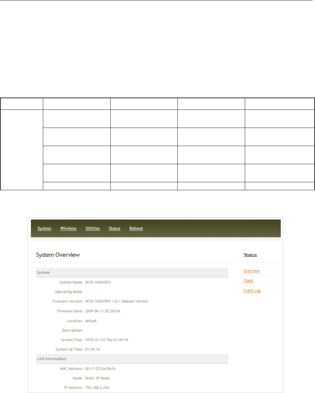
3.2.2.3 CPE Mode
Step 1 : Mode Confirmation
Ensure the Operating Mode is currently at CPE mode; the web management UI can be viewed at the Status
section under the System Overview page.
Step 2 : Change Password
Click System -> Management and then Admin Configuration page appears.
Enter a new password, and verify it again in the New Password and Check New Password field respectively.
Click Save button, and process with steps followed.
User Manual
TEW-455APBO 14dBi High Power Wireless Outdoor PoE Access Point
20
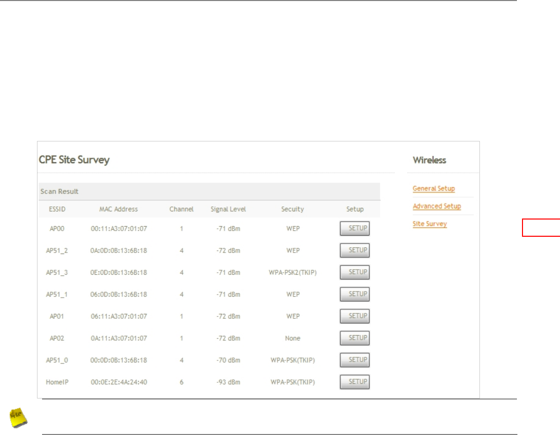
Step 3 : Site Survey
Click Wireless -> Site Survey, and then CPE Site Survey page appears. The system will automatically
scan and display the scan results on all BASE STATION existing near by the system.
Note : The scan result displayed here is an example only.
Step 4 : Select BASE STATION to be Associated
Search for the BASE STATION to be associated with from the Scan Result list provided in Step 3; use BS00
as an example here where the BASE STATION is encrypted via WEP security type.
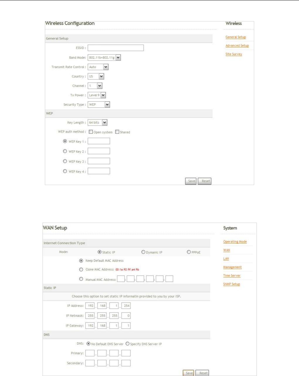
Step 5 : Security Settings
Click SETUP button of the BS00, and related information will display in Wireless Configuration page.
Enter the information required in the Wireless Configuration page. Information to be entered shall be exactly
the same as configured in the BS00 Base Station.
Click Save to save the settings.
User Manual
TEW-455APBO 14dBi High Power Wireless Outdoor PoE Access Point
21
Step 6 : WAN Settings
Click System -> WAN, and then WAN Setup page appears.
Enable “Static IP”, and then enter the related information. Click Save button to save the settings. (Default
WAN IP is 192.168.1.254)
BS00
User Manual
TEW-455APBO 14dBi High Power Wireless Outdoor PoE Access Point
22
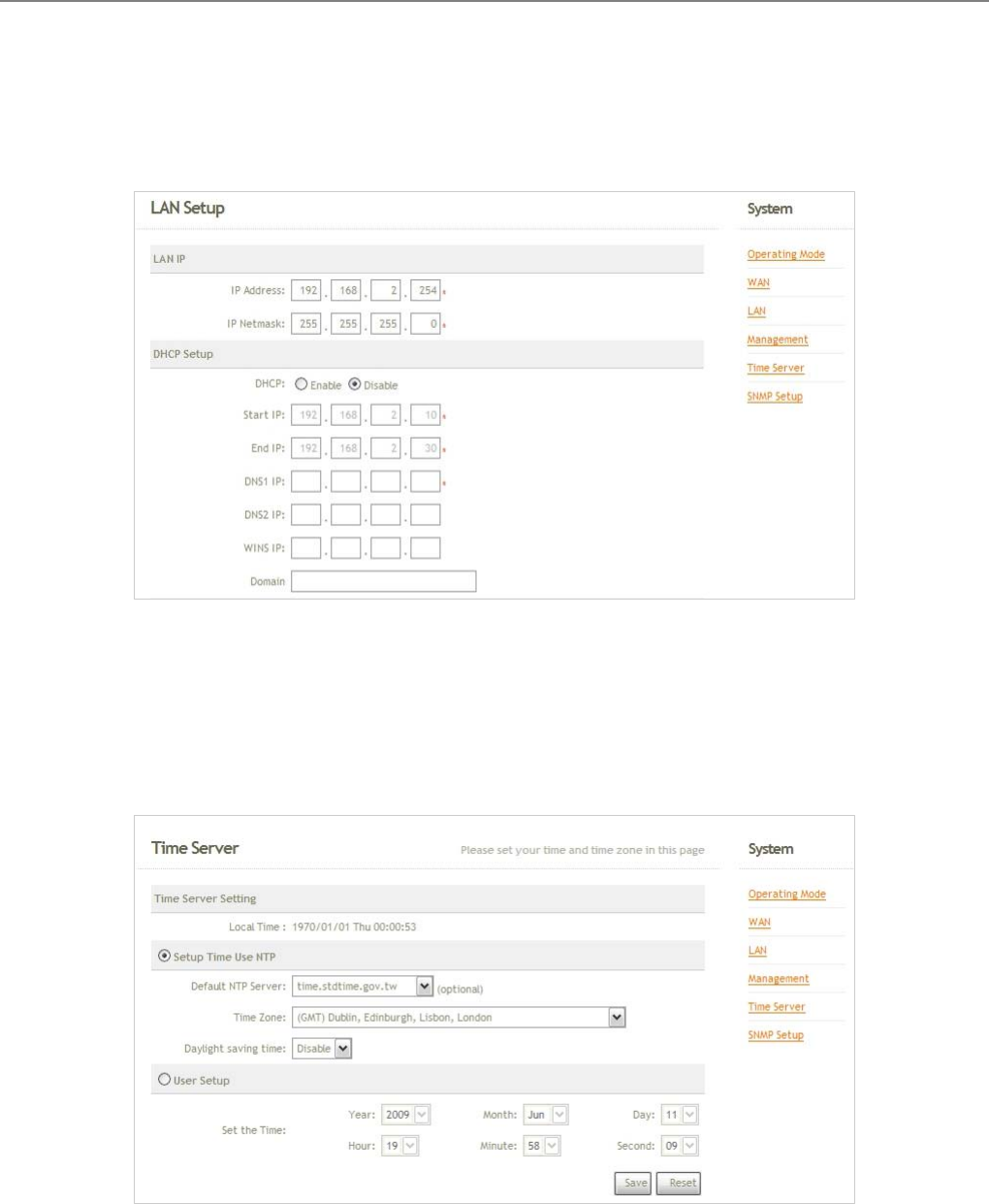
Step 7 : LAN Settings
Click System -> LAN, and then LAN Setup page appears.
Enter the “IP Address” and “IP Netmask” of the LAN Setup.
Step 8 : Time Zone settings
Click System -> Time Server, and then Time Server Setup page appears.
Enable “Setup Time Use NTP”, and then enter the related information. Click Save button to save the settings.
Click Reboot button to activate all settings configured so far.
Congratulation !
The CPE mode is now successfully configured.
User Manual
TEW-455APBO 14dBi High Power Wireless Outdoor PoE Access Point
23
Chapter 4. BASE STATION (Point to Point) Mode
Configuration
When BASE STATION mode is activated, the system can be configured as an Base station. This section provides
information in configuring the BASE STATION mode with graphical illustrations. TEW-455APBO provides functions
as stated below where they can be configured via a user-friendly web based interface.
Option System Wireless Utilities Status
Operating Mode General Settings Profiles Settings System Overview
LAN Advanced Settings Firmware Upgrade Associate Client Status
Management Virtual BASE
STATION Ping Utility Event Log
Time Server Reboot
Functions
SNMP
Table 4-1: BASE STATION Mode Functions
Figure 4-1: BASE STATION Mode Main Page
BS mode
User Manual
TEW-455APBO 14dBi High Power Wireless Outdoor PoE Access Point
24
4.1 System
This section provides information in configuring the following functions: Operating Mode, LAN Setup,
Management, Time Server, SNMP Setup
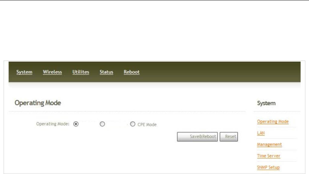
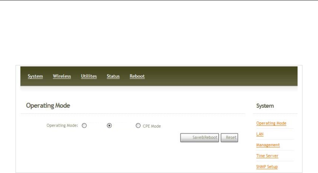
4.1.1 Operating Mode
TEW-455APBO supports three operation modes; BASE STATION mode , BRIDGE mode and CPE mode. The
administrator can set the desired mode via this page, and then configure the system according to their deployment
needs.
9 BS Mode : Check BS Mode button to enable BASE STATION mode, and then click “Save&Reboot” to
activate the setting.
9 B Mode : Check B Mode button to enable Bridge mode, and then click “Save&Reboot” to activate the
setting.
9 CPE Mode : Check CPE Mode button to enable CPE mode, and then click “Save&Reboot” to activate the
setting.
BS mode B mode

User Manual
TEW-455APBO 14dBi High Power Wireless Outdoor PoE Access Point
25
4.1.2 LAN Setup
Here is the instruction for how to setup the local IP Address and Netmask. Please click on System -> LAN and
follow the below setting.
Mode : Check either “Static IP” or “Dynamic IP” button as desired to set up the system IP of LAN port .
Î Static IP : The administrator can manually setup the LAN IP address when static IP is available/ preferred.
9 IP Address : The IP address of the LAN port; default IP address is 192.168.2.254
9 IP Netmask : The Subnet mask of the LAN port; default Netmask is 255.255.255.0
9 IP Gateway : The default gateway of the LAN port; default Gateway is 192.168.2.1
Î Dynamic IP : This configuration type is applicable when the WCB1000H5PX/ WCB1010H5PX is
connected to a network with the presence of a DHCP server; all related IP information will be provided by
the DHCP server automatically.
9 Hostname : The Hostname of the LAN port
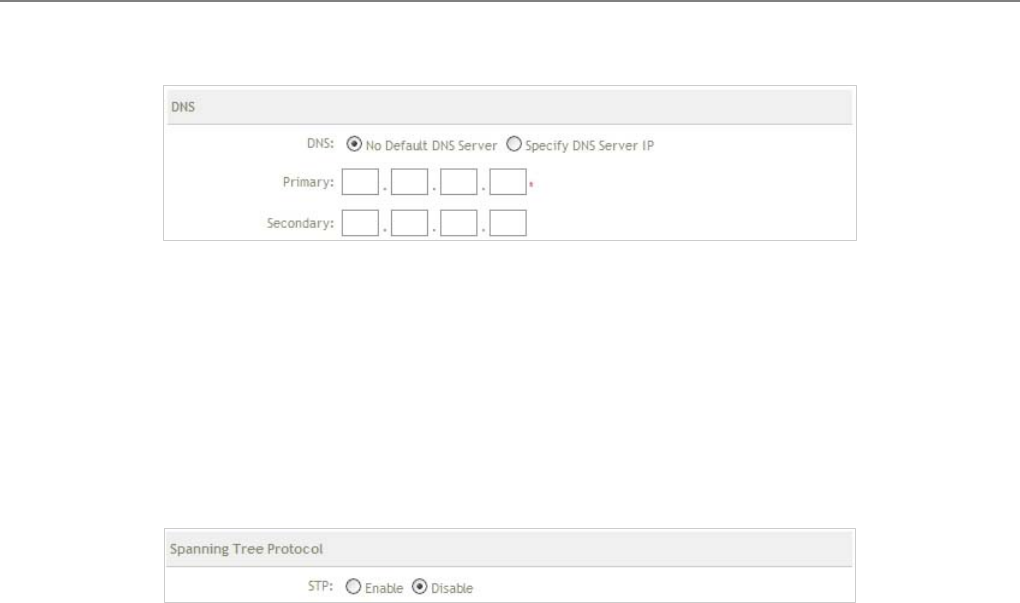
DNS : Check either “No Default DNS Server” or “Specify DNS Server IP” button as desired to set up the
system DNS.
User Manual
TEW-455APBO 14dBi High Power Wireless Outdoor PoE Access Point
26
Î Primary : The IP address of the primary DNS server.
Î Secondary : The IP address of the secondary DNS server.
Spanning Tree Protocol
The spanning tree network protocol provides a loop free topology for any bridged LAN. The Spanning Tree
Protocol, which is also referred to as STP, is defined in the IEEE Standard 802.1d.
Change these settings as described here and click Save button to save your changes. Click Reboot button to
activate your changes
User Manual
TEW-455APBO 14dBi High Power Wireless Outdoor PoE Access Point
27
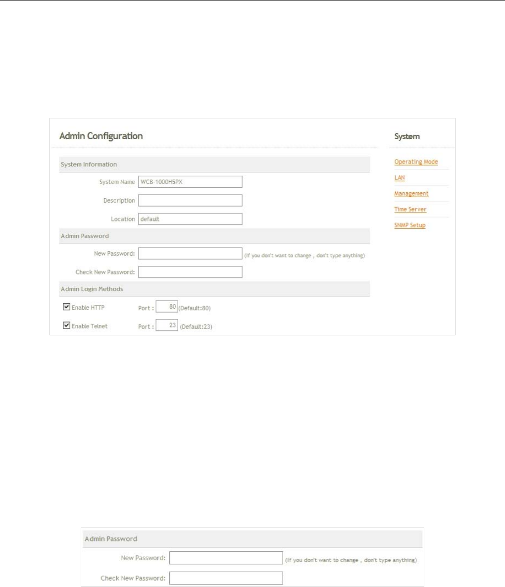
4.1.3 Management
The administrator can later obtain the geographical location of the system via the information configured here. The
administrator also can change system password and configure system login methods. Please click System ->
Management and follow the below settings.
System Information
Î System Name : Enter a desired name or use the default provided.
Î Description : Denote further information of the system.
Î Location : Enter related geographical location information of the system; administrator/manager will be
able to locate the system easily.
Admin Password : The admin manager can change its respected password. Enter the new password, and
then verify the new password in the Check New Password filed. Click Save button to activate the new
password.
Î New Password : Please input the new password of administrator.
Î Check New Password : Please input again the new password of administrator.

User Manual
TEW-455APBO 14dBi High Power Wireless Outdoor PoE Access Point
28
Admin Login Methods : The admin manager can enable or disable system login methods, it also can change
services port. Click Save button to activate the admin login methods.
Î Enable HTTP : Select Enable HTTP to activate HTTP Service
Î HTTP Port : Please input 1 ~ 65535 value to set HTTP Port; default value is 80
Î Enable Telnet : Select Enable HTTP to activate HTTP Service
Î Telnet Port : Please input 1 ~ 65535 value to set HTTP Port; default value is 23
Change these settings as described here and click Save button to save your changes. Click Reboot button to
activate your changes

User Manual
TEW-455APBO 14dBi High Power Wireless Outdoor PoE Access Point
29
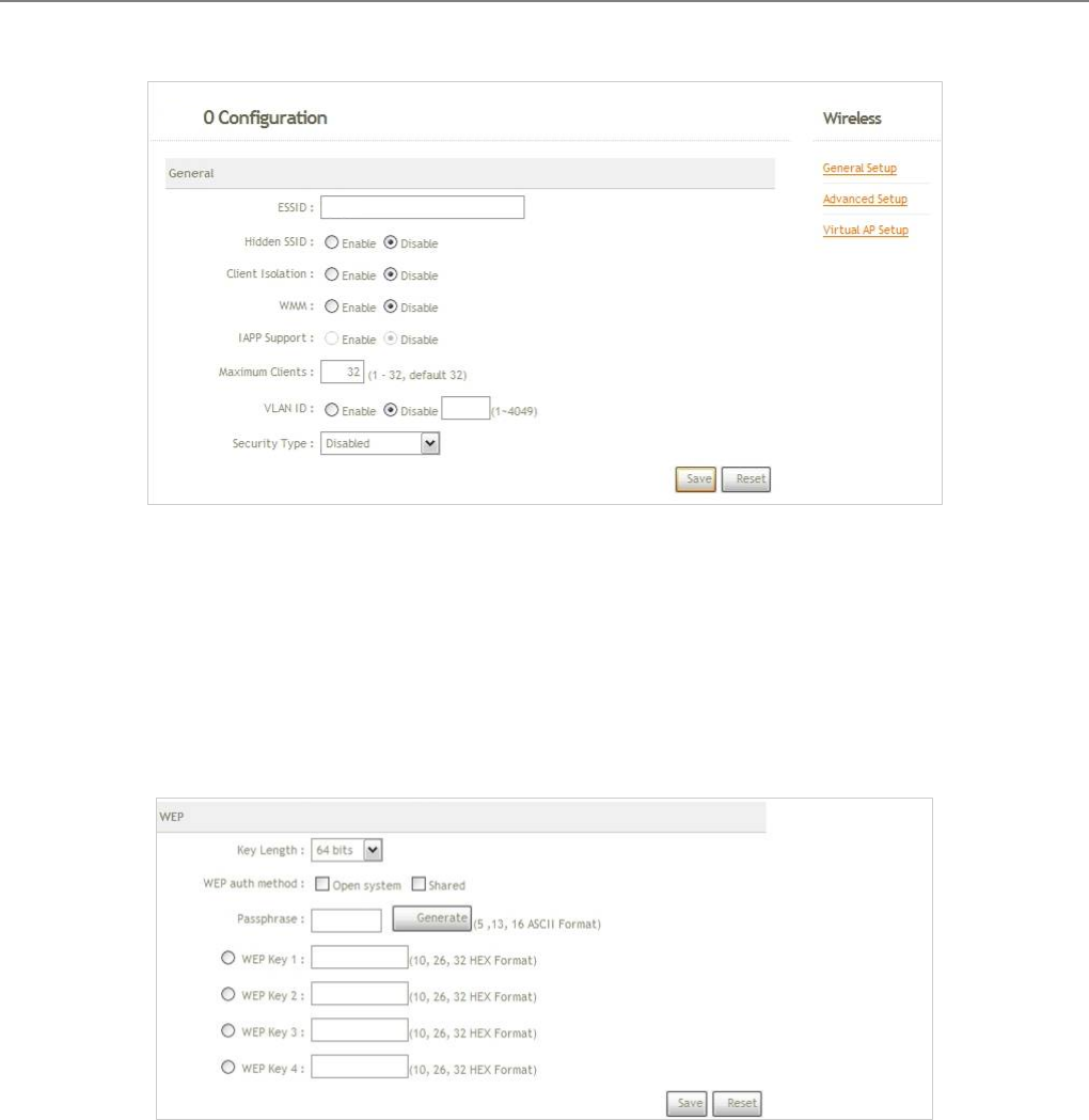
4.1.4 Time Server
System time can be configured via this page where manual setting and NTP server configuration are both
supported. Please click on System -> Time Server and follow the below setting.
Local Time : Display the current time of the system.
Setup Time Use NTP : Enable Network Time Protocol, NTP, to synchronize the system time with NTP server.
Î Default NTP Server : Select the NTP Server from the drop-down list.
Î Time Zone : Please set a time zone from where the accurate time can be supplied, (GMT+08:00) Taipei
for example.
Î Daylight saving time : Enable Daylight saving time from where the accurate time needed.
User Setup : Enable User Setup and Click Set Time button; the system time can be configured manually.
Î Set Time : Click Set Time button, the Time field should be changed automatically.
Î Set the time : Select the appropriate Year, Month, Day, Hour, Minute and Second from the drop-down
list.
Change these settings as described here and click Save button to save your changes. Click Reboot button to
activate your changes

User Manual
TEW-455APBO 14dBi High Power Wireless Outdoor PoE Access Point
30
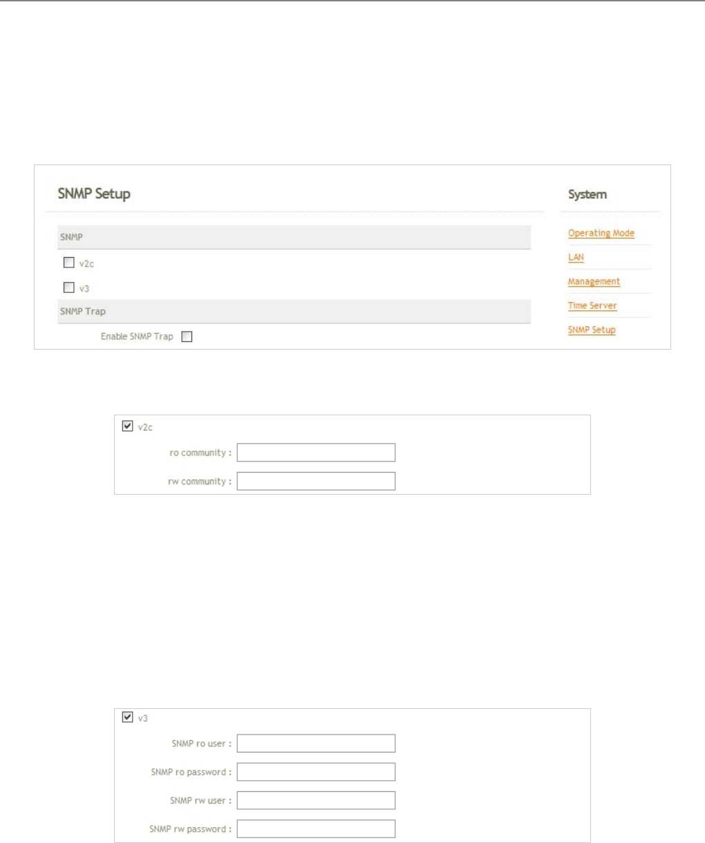
4.1.5 SNMP Setup
SNMP is an application-layer protocol that provides a message of format for communication between SNMP
managers and agents. By enabling SNMP function, the administrator can obtain the system information remotely.
Please click on System -> SNMP Setup and follow the below setting.
v2c : Check v2c button to activate SNMP v2c agent or unchecked to deactivate this function.
Î ro community : Enter the community strings that allows read-only access to the system's SNMP
information.
Î rw community : Enter the community strings that allows read/write access to the system's SNMP
information.
v3 : Check v3 button to activate SNMP v3 agent or unchecked to deactivate this function. SNMPv3 supports
the highest available levels of security for SNMP communication.
Î SNMP ro user : Enter the community strings that allows read-only access to the system's SNMP
information.
Î SNMP ro password : Enter the password that allows read-only access to the system's SNMP information.
Î SNMP rw user : Enter the community strings that allows read/write access to the system's SNMP
User Manual
TEW-455APBO 14dBi High Power Wireless Outdoor PoE Access Point
31
information.
Î SNMP rw password : Enter the password that allows read/write access to the system's SNMP
information.
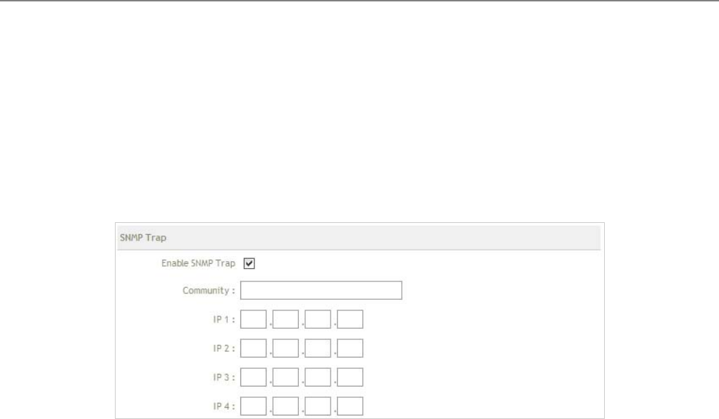
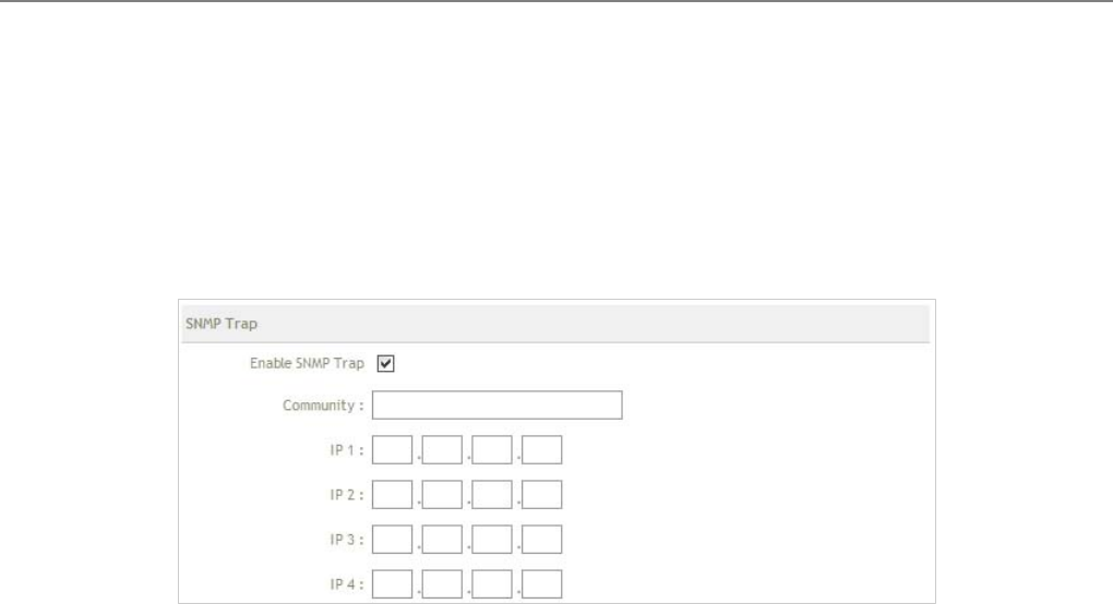
SNMP Trap : Events on cold start, interface up & down, and association & disassociation can be reported via
this function to an assigned server.
Î Community : Enter the community strings required by the remote host computer that will receive trap
messages or notices send by the system.
Î IP : Enter the IP address of the remote host computer that will receive the trap messages.
Change these settings as described here and click Save button to save your changes. Click Reboot button to
activate your changes
User Manual
TEW-455APBO 14dBi High Power Wireless Outdoor PoE Access Point
32
4.2 Wireless
The system manager can configure related wireless settings, General Settings, Advanced Settings, Virtual
BASE STATION Setting, Security Settings, and Access Control Settings.
Virtual BS mode
User Manual
TEW-455APBO 14dBi High Power Wireless Outdoor PoE Access Point
33
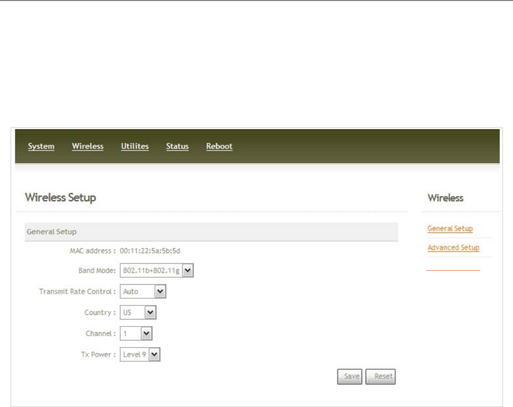
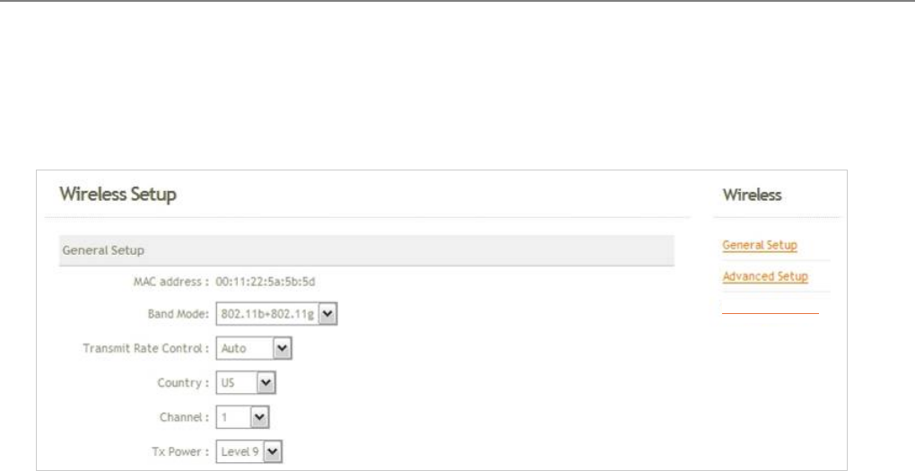
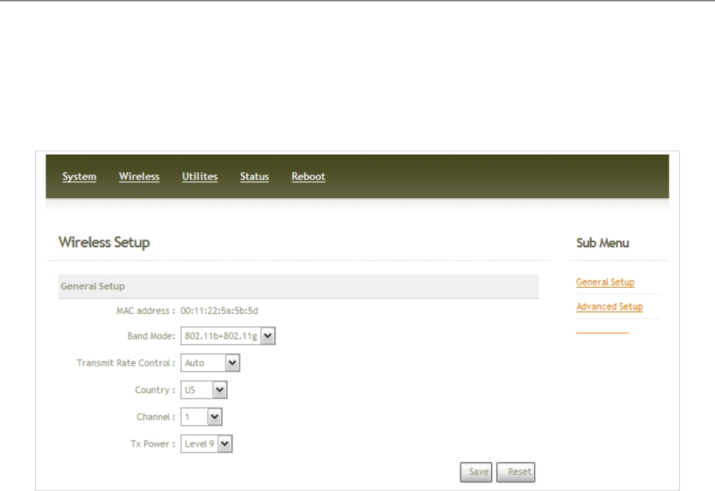
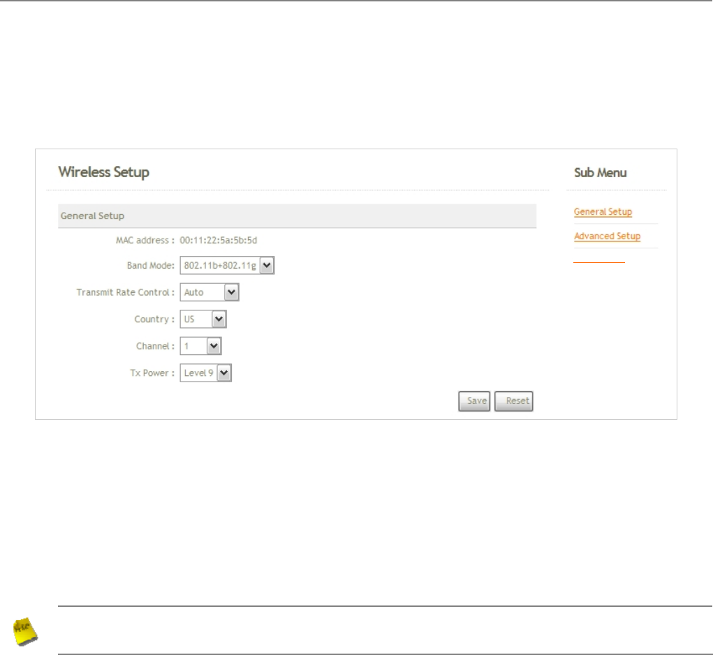
4.2.1 General Setup
The administrator can change the data transmission, channel and output power settings for the system. Please
click on Wireless -> General Setup and follow the below setting.
MAC address : The MAC address of the Wireless interface is displayed here.
Band Mode : Select an appropriate wireless band; bands available are 801.11b, 802.11g and
802.11b+802.11g.
Transmit Rate Control : Select the desired rate from the drop-down list; the options are auto or ranging from
1 to 54Mbps for 802.11g and 802.11b/g modes, or 1 to 11Mbps for 802.11b mode.
Country : Select the desired country code from the drop-down list; the options are US, ETSI and Japan.
Channel : The channel range will be changed by selecting different country code. The channel range from 1 to
11 for US country code, or 1 to 13 for ETSI country code, or 1 to 14 for Japan.
Tx Power : You can adjust the output power of the system to get the appropriate coverage for your wireless
network. Select the LEVEL 1 to LEVEL 9 you needed for your environment. If you are not sure of which
setting to choose, then keep the default setting, LEVEL 9.
Change these settings as described here and click Save button to save your changes. Click Reboot button to
activate your changes. The items in this page are for BASE STATION's RF general settings and will be applied to
all VBSs.
Virtual BS mode
User Manual
TEW-455APBO 14dBi High Power Wireless Outdoor PoE Access Point
34
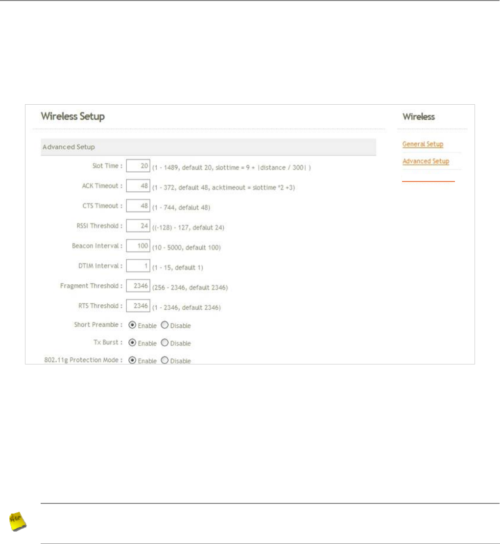
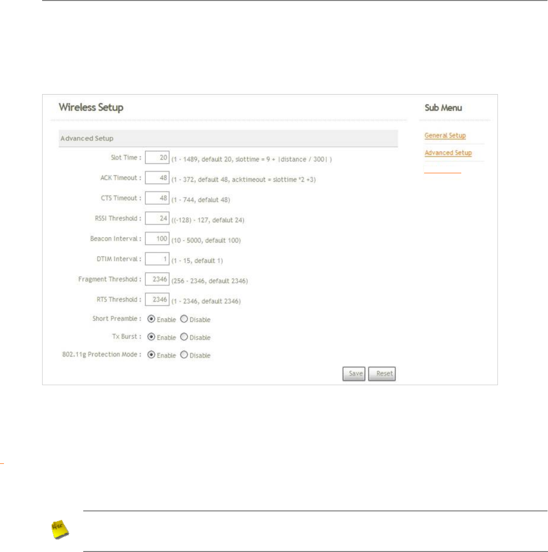
4.2.2 Advanced Setup
The administrator can change the Slot Time, ACK/CTS Timeout, RTS threshold and fragmentation threshold
settings for the system. Please click on Wireless -> Advanced Setup and follow the below setting.
Slot Time : Enter the desired slot time for the BASE STATION.
ACK Timeout : The time interval for waiting the “ ACKnowledgment frame”. If the ACK is not received within
that timeout period then the packet will be re-transmitted. Higher ACK Timeout will decrease the packet lost,
but the throughput will be growing worse.
CTS Timeout : Enter the desired CTS timeout for the BASE STATION.
Note : Slot Time and ACK/CTS Timeout settings for long distance links. It is important to change the
value to find the optimal setting. A value too low will give very low throughput, A high value may
slowdown the link.
RSSI Threshold : RSSI Threshold can be used to control the level of noise received by the device.
Beacon Interval : Enter a value between 10 and 5000 msec. The default value is 100 milliseconds. The
entered time means how often the beacon signal transmission between the base station and the wireless
network.
Virtual BS mode

User Manual
TEW-455APBO 14dBi High Power Wireless Outdoor PoE Access Point
35
DTIM Interval : Input the DTIM Interval that is generated within the periodic beacon at a specified frequency.
Higher DTIM will let the wireless client save energy more, but the throughput will be growing worse.
Fragment Threshold : The value specifies the maximum size of packet allowed before data is fragmented into
multiple packets. Please use this value to tune the wireless connection if lots of retransmission happens. Enter
a value ranging from 256 to 2346.
RTS Threshold : Tuning the Request to Send, RTS threshold will help the system control its access to
medium and alleviate the hidden node problem. Enter a value ranging from 1 to 2346.
Short Preamble : The short preamble provides 56-bit Synchronization field to improve WLAN transmission
efficiency. Check Enable button for using Short Preamble, and Disable for using the Long Preamble, 128-bit
Synchronization field, option.
Tx Burst : Click Enable button to activated Tx Burst, and Disable to deactivated Tx Burst.
802.11g Protection Mode : Click Enable button to activated 802.11g Protection Mode, and Disable to
deactivated 802.11g Protection Mode.
Change these settings as described here and click Save button to save your changes. Click Reboot button to
activate your changes. The items in this page are for BASE STATION's RF advanced settings and will be applied to
all VBSs.
User Manual
TEW-455APBO 14dBi High Power Wireless Outdoor PoE Access Point
36
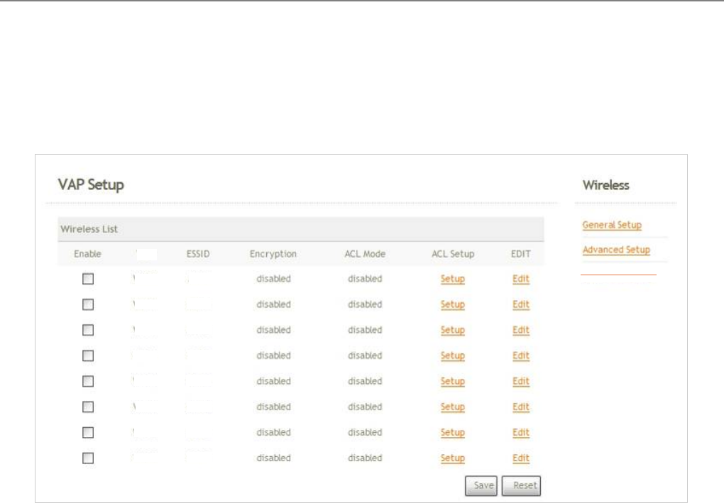
4.2.3 Virtual BASE STATION Setup
The administrator can create Virtual BASE STATION via this page. Please click on Wireless -> Virtual BS
STATION Setup and follow the below setting.
Enable : Click Enable button and Save button for creating Virtual BASE STATION
VBS : Display number of system's Virtual BASE STATION.
ESSID : Display Virtual BASE STATION's ESSID; default is BS00~BS07.
Encryption : Display Virtual BASE STATION's Security Type; default is disabled.
ACL Mode : Display Virtual BASE STATION's ACL Mode; default is disabled.
ACL Setup : Click Setup button for configuring Virtual BASE STATION's Access Control List.
EDIT : Click Edit button for configuring Virtual BASE STATION's settings and security type.
Change these settings as described here and click Save button to save your changes. Click Reboot button to
activate your changes
Virtual BS mode
VBS
VBS 0
V
BS 1
VBS 2
VBS
VBS 4
VBS 3
VBS 6
VBS 5
V
BS 7
BS00
BS01
BS02
BS03
BS04
BS05
BS06
BS07
User Manual
TEW-455APBO 14dBi High Power Wireless Outdoor PoE Access Point
37
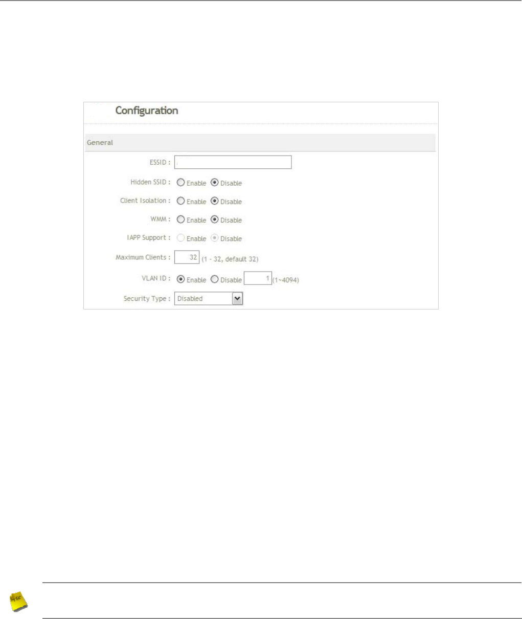
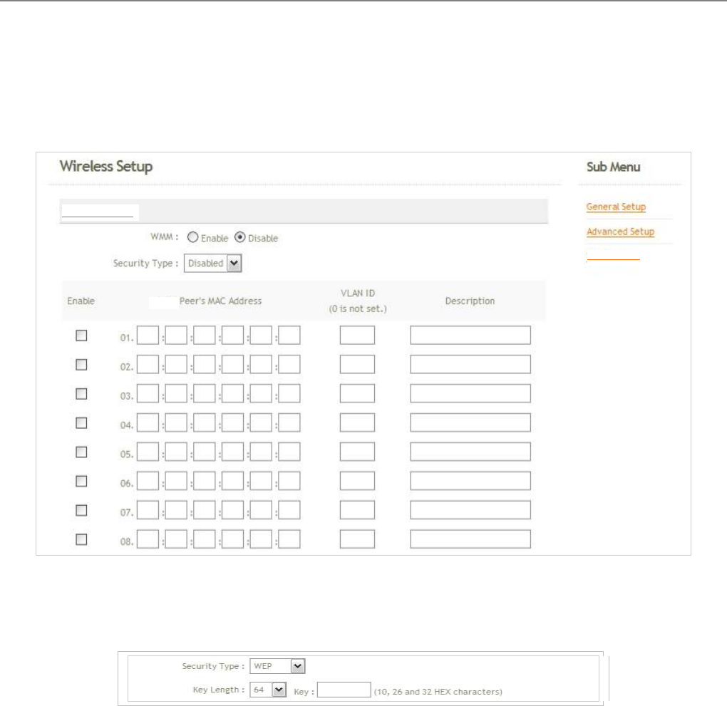
4.2.3.1 Virtual BASE STATION General Configuration
For each Virtual BASE STATION, administrators can configure general settings and wireless security type. Click
Wireless -> Virtual BASE STATION -> EDIT, and then Virtual BASE STATION Configuration page appears.
ESSID : Extended Service Set ID indicates the SSID which the clients used to connect to the VBS. ESSID will
determine the service type of a client which is assigned to the specified VBS.
Hidden SSID : Select this option to enable the SSID to broadcast in your network. When configuring the
network, it is suggested to enable this function but disable it when the configuration is complete. With this
enabled, someone could easily obtain the SSID information with the site survey software and get unauthorized
access to a private network. With this disabled, network security is enhanced and can prevent the SSID from
begin seen on networked.
Client Isolation : Select Enable, all clients will be isolated each other, that means all clients can not reach to
other clients.
WMM : Select Enable, the packets with QoS WMM will has higher priority.
IBSP Support : Inter Access-Point Protocol is designed for the enforcement of unique association throughout
a ESS(Extended Service Set) and for secure exchange of station's security context between current base
station (BS) and new BS during hand off period.
Note : IBSP supported only for WPA-PSK/WPA2-PSK, WPA-Enterprise/WPA2-Enterprise and 802.1X
security type.
Maximum Clients : Enter maximum number of clients to a desired number. For example, while the number
of client is set to 5, only 5 clients are allowed to connect with this VBSF.
VLAN ID : Virtual LAN, the system supports tagged VLAN. To enable VLAN function; valid values are from 1 to
4094.
V
BS 0
BS00
User Manual
TEW-455APBO 14dBi High Power Wireless Outdoor PoE Access Point
38
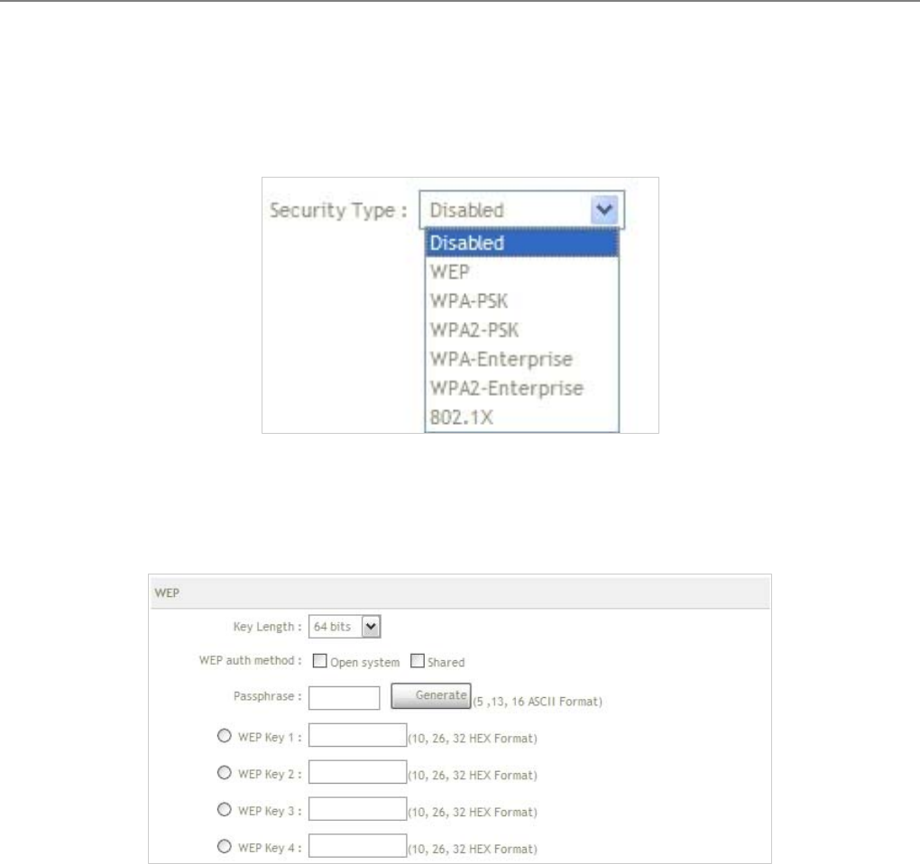
Security Type : Select the desired security type from the drop-down list; the options are WEP, WPA-PSK,
WPA2-PSK, WPA-Enterprise, WPA2-Enterprise and 802.1X.
Î Disable : Data are unencrypted during transmission when this option is selected.
Î WEP : WEP, Wired Equivalent Privacy, is a data encryption mechanism based on a 64-bit, 128-bit or 152-
bit shared key. Select WEP as the security type from the drop down list as desired.
9 Key Length : Select the desire options which are 64 bits, 128 bits or 152 bits from drop-down list.
9 WEP auth Method : Enable the desire option among Open system or Shared.
9 Passphrase : Enter ASCII format in this field. Click Generate button, and then selected key value will
be filled.
9 WEP Key # : Select key index is used to designate the WEP key during data transmission. Enter HEX
format WEP key value; the system support up to 4 sets of WEP keys.
User Manual
TEW-455APBO 14dBi High Power Wireless Outdoor PoE Access Point
39
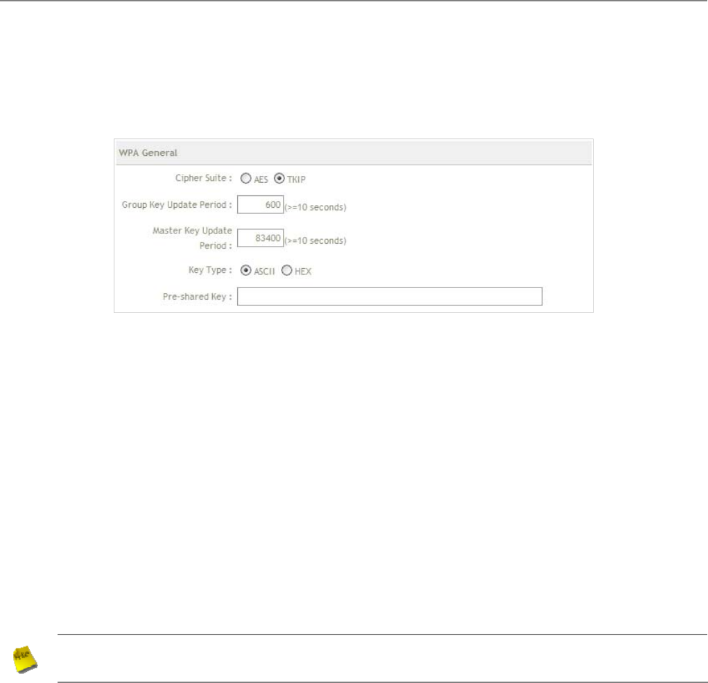
Î WPA-PSK (or WPA2-PSK) : WPA (or WPA2) Algorithms, allows the system accessing the network by
using the WPA-PSK protected access.
9 Cipher Suite : Check on the respected button to enable either AES or TKIP cipher suites; default is
TKIP.
9 Group Key Update Period : This time interval for re-keying GTK (broadcast/multicast encryption
keys) in seconds. Enter the time-length required; the default time is 600 seconds.
9 Master Key Update Period : This time interval for re-keying GMK (master key used internally to
generate GTKs) in seconds. Enter the time-length required; the default time is 83400 seconds.
9 Key Type : Check on the respected button to enable either ASCII or HEX format for the Pre-shared
Key.
9 Pre-shared Key : Enter the information for pre-shared key; the format of the information shall
according to the key type selected.
Note : Pre-shared key can be either entered as a 256-bit secret in 64 HEX digits format, or 8 to 63 ASCII
characters.
User Manual
TEW-455APBO 14dBi High Power Wireless Outdoor PoE Access Point
40
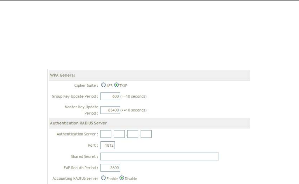
Î WPA-Enterprise (or WPA2-Enterprise): The RADIUS authentication and encryption will be both enabled
if this selected.
9 WPA General Settings :
• Cipher Suite : Check on the respected button to enable either AES or TKIP cipher suites.
• Group Key Update Period : This time interval for re-keying GTK (broadcast/ multicast
encryption keys) in seconds. Enter the time-length required; the default time is 600 seconds.
• Master Key Update Period : This time interval for re-keying GMK (master key used internally to
generate GTKs) in seconds. Enter the time-length required; the default time is 83400 seconds.
9 Authentication RADIUS Server Settings :
• Authentication Server : Enter the IP address of the Authentication RADIUS server.
• Port : The port number used by Authentication RADIUS server. Use the default 1812 or enter
port number specified.
• Shared secret : The secret key for system to communicate with Authentication RADIUS server.
Support 1 to 64 characters.
• EAP Reauth Period : EAP re-authentication period in seconds; default is 3600; 0 = disable re-
authentication.
• Accounting Server : Check on the respected button to enable either Enable or Disable
accounting RADIUS server.
User Manual
TEW-455APBO 14dBi High Power Wireless Outdoor PoE Access Point
41
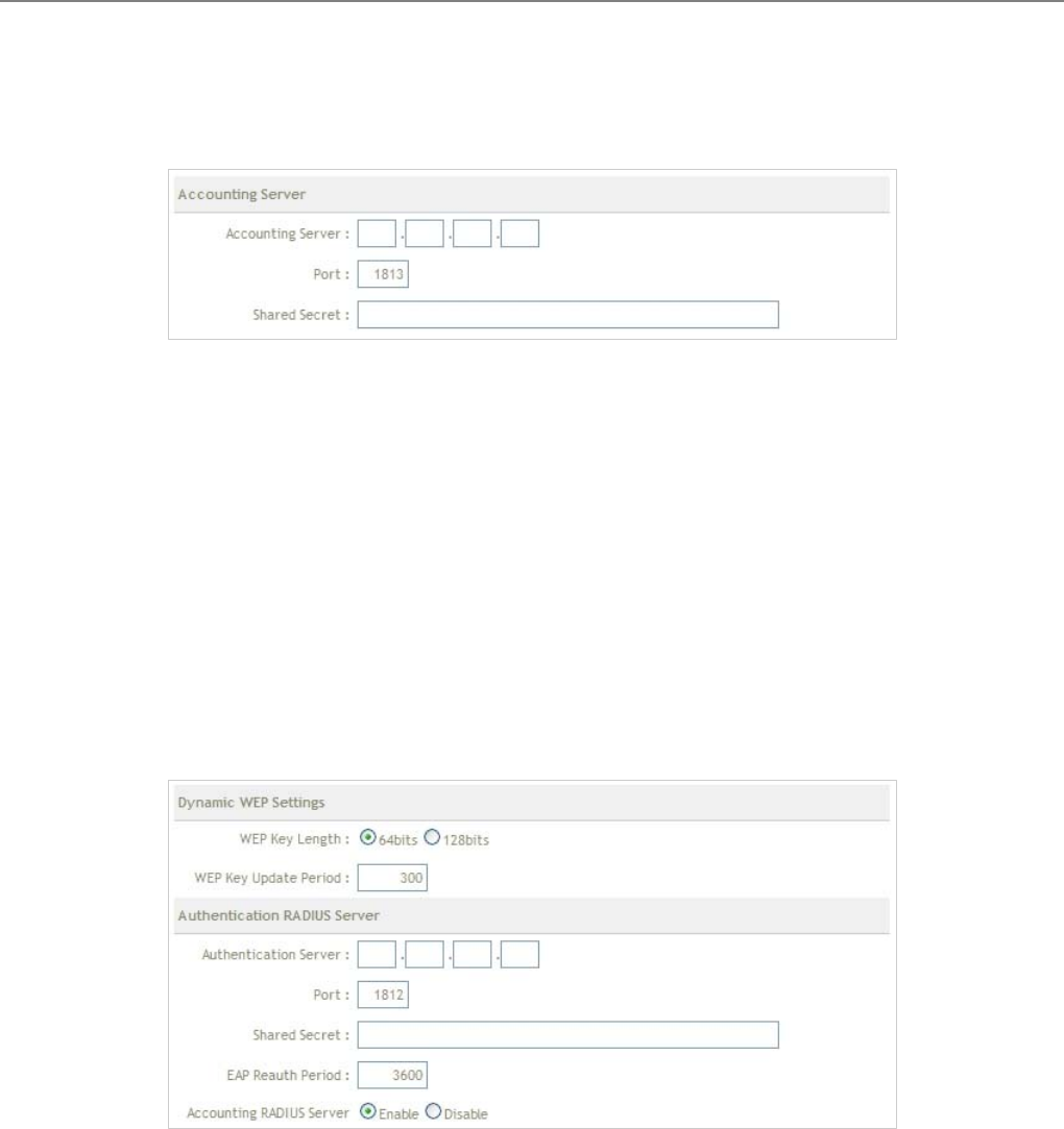
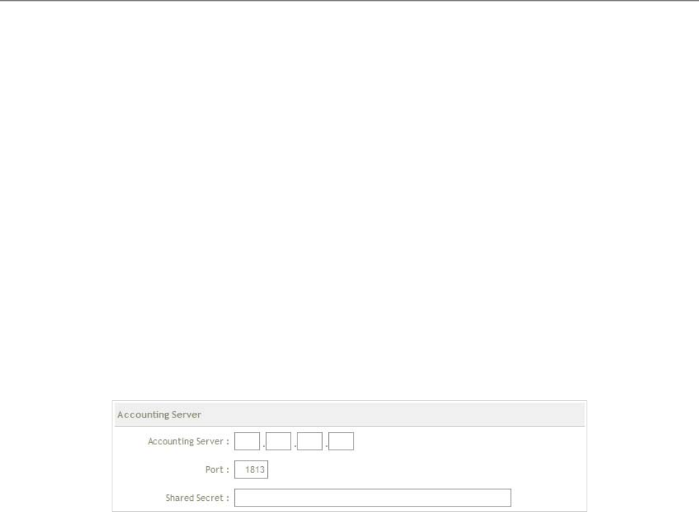
9 Accounting Server Settings :
• Accounting Server : Enter the IP address of the Accounting RADIUS server.
• Port : The port number used by Accounting RADIUS server. Use the default 1813 or enter port
number specified.
• Shared Secret : The secret key for system to communicate with Accounting RADIUS server.
Support 1 to 64 characters.
Î 802.1X : When 802.1x Authentication is enabled, please refer to the following Dynamic WEP and RADIUS
settings to complete the configuration.
9 Dynamic WEP Settings :
• WEP Key length : Check on the respected button to enable either 64bits or 128bits key length.
The system will automatically generate WEP keys for encryption.
• WEP Key Update Period : The time interval WEP will then be updated; the unit is in seconds;
default is 300 seconds; 0 = do not re-key.
• Group Key Update Period : This time interval for re-keying GTK (broadcast/ multicast
encryption keys) in seconds. Enter the time-length required; the default time is 600 seconds.
User Manual
TEW-455APBO 14dBi High Power Wireless Outdoor PoE Access Point
42
9 Authentication RADIUS Server Settings :
• Authentication Server : Enter the IP address of the Authentication RADIUS server.
• Port : The port number used by Authentication RADIUS server. Use the default 1812 or enter
port number specified.
• Shared secret : The secret key for system to communicate with Authentication RADIUS server.
Support 1 to 64 characters.
• EAP Reauth Period : EAP reauthentication period in seconds; default is 3600; 0 = disable
reauthentication.
• Accounting Server : Check on the respected button to enable either Enable or Disable
accounting RADIUS server.
9 Accounting Server :
• Accounting Server : Enter the IP address of the Accounting RADIUS server.
• Port : The port number used by Accounting RADIUS server. Use the default 1813 or enter port
number specified
• Shared Secret : The secret key for system to communicate with Accounting RADIUS server.
Support 1 to 64 characters.
Change these settings as described here and click Save button to save your changes. Click Reboot button to
activate your changes
User Manual
TEW-455APBO 14dBi High Power Wireless Outdoor PoE Access Point
43
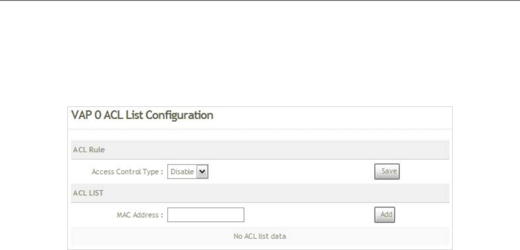
4.2.3.2 Virtual BS Access Control List (ACL) Setup
In this function, the administrator can be allow or reject clients to access Virtual BS. Please click on Wireless ->
Virtual BS Setup -> ACL Setup and follow the below setting.
Access Control Type : Select the desired access control type from the drop-down list; the options are Disable,
Allow or Reject.
MAC Address : Enter MAC address in this field. There are 20 users maximum allowed in this MAC address
list.
Change these settings as described here and click Save button to save your changes. Click Reboot button to
activate your changes
User Manual
TEW-455APBO 14dBi High Power Wireless Outdoor PoE Access Point
44
4.3 Utilities
The administrator can maintain the system via this page: Profile Setting, System Upgrade, Ping Utility, and
Reboot.
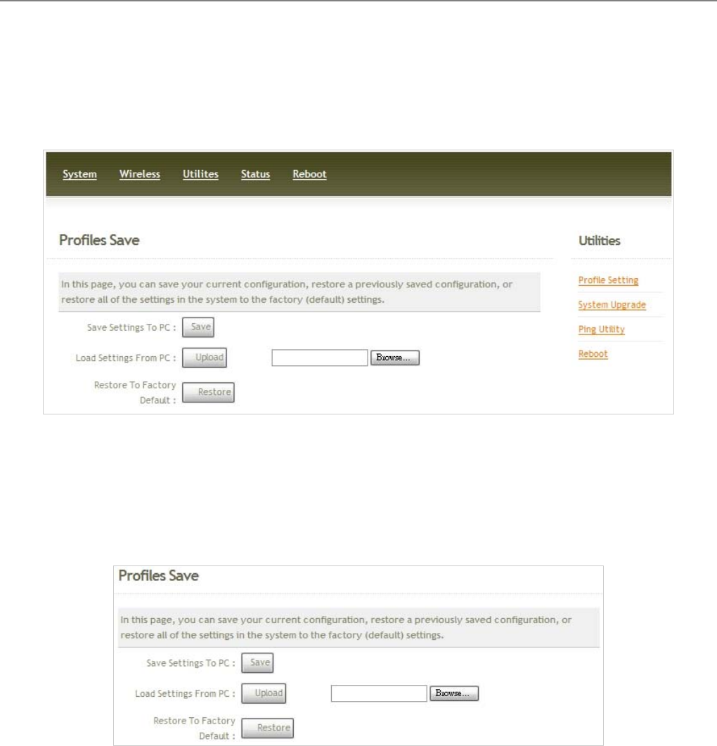
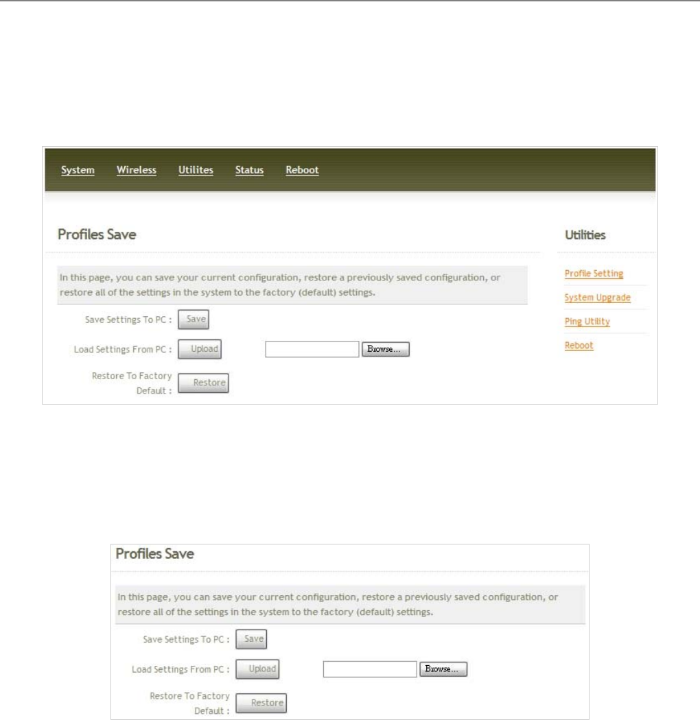
4.3.1 Profile Setting
Current settings on the system can be backed up, or previous backed up settings can be restored as well as
resetting the system back to factory default can be performed via this page. Please click on Utilities -> Profile
Setting and follow the below setting.
Save Settings to PC : Click Save button to save the current system settings to a local disk, i.e. the HDD of a
local computer or Compact Disc.
Load Settings from PC : Click Browse button to search for a previously saved backup file, and then click
Upload button to upload the settings; the system will then be configured to the same settings as specified by
the backup file.
Restore To Factory Default : Click Restore button to load the factory default settings of WCB1000H5PX/
WCB1010H5PX, and then Success Message page appears. Click Reboot button to set default configuration.
User Manual
TEW-455APBO 14dBi High Power Wireless Outdoor PoE Access Point
45
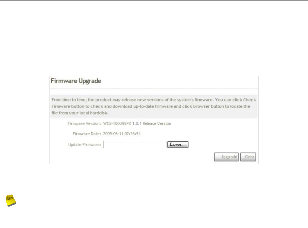
4.3.2 Firmware Upgrade
To upgrade the system firmware, click Browse to search for the new firmware file, and then click Upgrade button
to execute the upgrade process.
Note :
1. To prevent data loss during firmware upgrade, please back up the current settings before
proceeding to firmware upgrade.
2. Please restart the system after the upgrade. Do not interrupt the system, i.e. power on/off, during
the upgrading process or the restarting process as this may damage system.
User Manual
TEW-455APBO 14dBi High Power Wireless Outdoor PoE Access Point
46
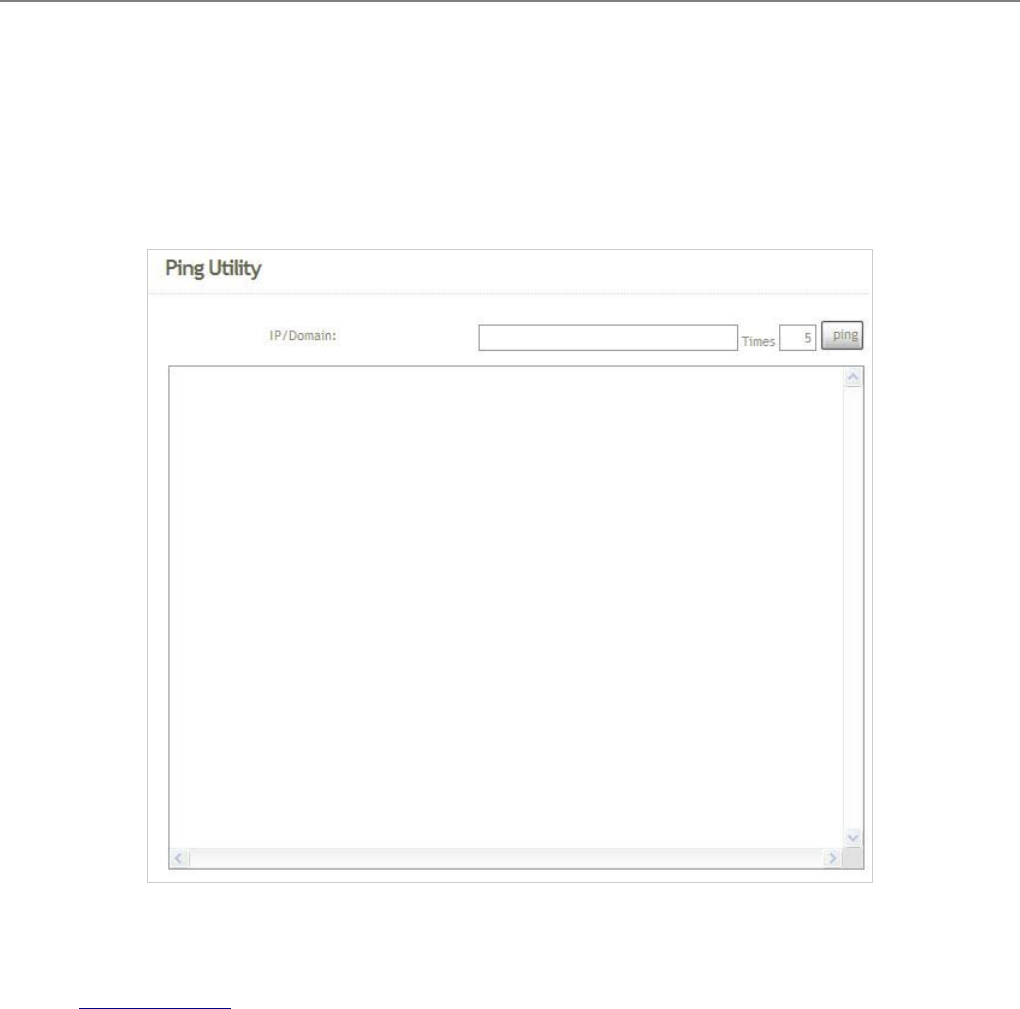
4.3.3 Ping Utility
The administrator can diagnose the network connectivity via this function. Please click on
Utilities -> Ping Utility and follow the below setting.
Î IP/Domain : Enter the desired domain name or IP address of the target device for diagnosis purpose, i.e.
www.google.com, and click ping button to proceed. The ping result will be shown in the Result field.
Î Time : Enter the time for ping utility; default is 5, maximum is 50.

User Manual
TEW-455APBO 14dBi High Power Wireless Outdoor PoE Access Point
47
4.3.4 Reboot
This function allows the administrator to safely restart the TEW-455APBO. Click Reboot to restart the system
immediately, and the whole process will take about three minutes to complete.
The Restart page as displayed below appears during the rebooting period. If turning off the power is necessary,
please allow the restart process to be completed before turning off the system.
The System Overview page appears upon the completion of reboot.
User Manual
TEW-455APBO 14dBi High Power Wireless Outdoor PoE Access Point
48
4.4 Status
Information of the current system settings can be reviewed via this page; statuses of Overview, Clients, and Event
Log are displayed in this interface.
BS Mode
User Manual
TEW-455APBO 14dBi High Power Wireless Outdoor PoE Access Point
49
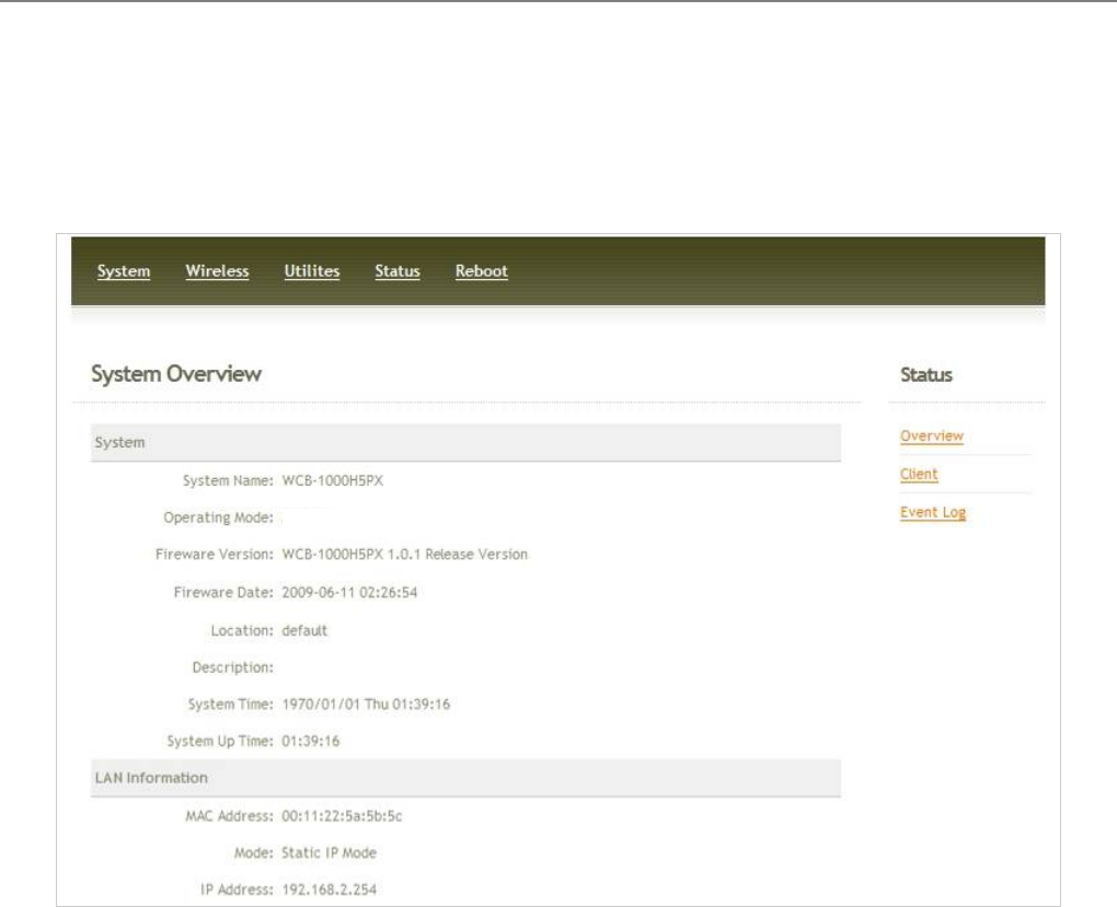
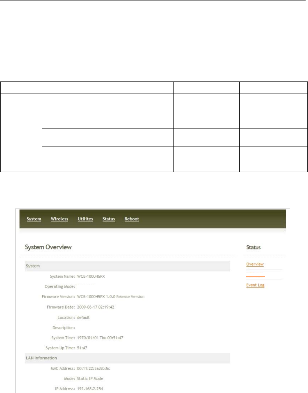
4.4.1 Overview
Detailed information on System, LAN Information, and Wireless Information can be reviewed via this page.
System : Display the information of the system.
Î System Name : The name of the system.
Î Operating Mode : The mode currently in service.
Î Firmware Version : The current firmware version installed.
Î Firmware Date : The build time of the firmware installed.
Î Location : The reminding note on the geographical location of the system. For more information, please
refer to Section 4.1.3-Management .
Î Description : Please refer to Section 4.1.3-Management .
Î System Time : The current time of the system.
Î System Up Time : The time period that the system has been in service since last boot-up.
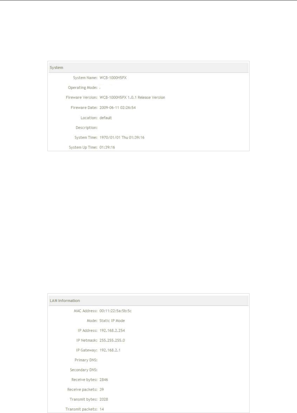
LAN Information : Display the information of the LAN interface.
BS Mode
User Manual
TEW-455APBO 14dBi High Power Wireless Outdoor PoE Access Point
50
Î MAC Address : The MAC address of the LAN port.
Î Mode : The current mode of the LAN port.
Î IP Address : The IP address of the LAN port.
Î IP Netmask : The IP netmask of the LAN port.
Î IP Gateway : The gateway IP address of the LAN port.
Î Primary DNS : The current primary DNS server of the system.
Î Secondary DNS : The current secondary DNS server of the system.
Î Receive bytes :The current receive bytes of the LAN port.
Î Receive packets : The current receive packets of the LAN port.
Î Transmit bytes : The current transmit bytes of the LAN port.
Î Transmit packets : The current transmit packets of the LAN port.
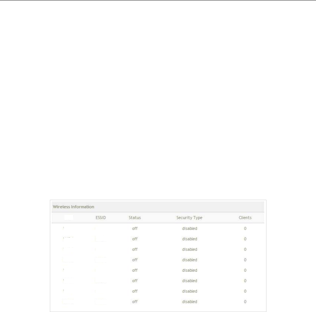
Wireless Information : Display the Virtual BS configuration information of the system.
Î VBS : Display number of system's Virtual BS.
Î ESSID : Extended Service Set ID of the Virtual BS.
Î Status : Display Virtual BS status currently.
Î Security Type : Security type activated by the Virtual BS.
Î Clients : Number of clients currently associated to the Virtual BS.
VBS
VBS 0
V
BS 1
VBS 2
VBS
VBS 4
VBS 3
VBS 6
VBS 5
V
BS 7
BS00
BS01
BS02
BS03
BS04
BS05
BS06
BS07
User Manual
TEW-455APBO 14dBi High Power Wireless Outdoor PoE Access Point
51
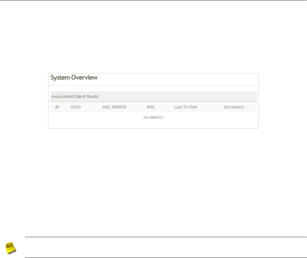
4.4.2 Client
The administrator can obtain detailed Information such as VBS, ESSID, MAC Address, RSSI, and Idle Time of all
associated clients via this page.
BS : Virtual BS which the device is associated with.
ESSID : ESSID which the device is associated with.
RSSI : Indicate the RSSI of the respective client's association.
Idle Time : Time period that the associated client is inactive (units in seconds).
Disconnect : Administrator can kick out a specific client, click Kick button to disconnect specific client
Note : In Disconnect function of Associated Client Status, the client may be re-connect immediately. IF
you want deny client associate system, please refer to Section 4.3.2-Virtual BS ACL Configuration.

User Manual
TEW-455APBO 14dBi High Power Wireless Outdoor PoE Access Point
52
4.4.3 Event Log
The reported system events can be reviewed here.
Date/ Time: The date and time when the event occurred.
Hostname: The name of the host which records the event. It helps the administrator identify the source of the
reported events.
Process name (with square brackets): Indicate the process with which the specific event is associated.
Description: Description of the event.
Click Refresh button to renew the log, or click Clear button to clear all the record.
User Manual
TEW-455APBO 14dBi High Power Wireless Outdoor PoE Access Point
53
Chapter 5. BRIDGE Mode Configuration
When BRIDGE mode is activated, the system can be configured as a repeater or client bridge. This section
provides information in configuring the BRIDGE mode with graphical illustrations. TEW-455APBO provides
functions as stated below where they can be configured via a user-friendly web based interface.
Option System Wireless Utilities Status
Operating Mode General Settings Profiles Settings System Overview
LAN Advanced Settings Firmware Upgrade BRIDGE List
Management BRIDGE Setup Ping Utility Event Log
Time Server Reboot
Functions
SNMP
Table 5-1: BRIDGE Mode Functions
Figure 5-1: BRIDGE Mode Main Page
B Mode
Bridge List
User Manual
TEW-455APBO 14dBi High Power Wireless Outdoor PoE Access Point
54
5.1 System
This section provides information in configuring the following functions: Operating Mode, LAN Setup,
Management, Time Server, SNMP Setup
5.1.1 Operating Mode
TEW-455APBO supports three operation modes; BS mode, BRIDGE mode and CPE mode. The administrator can
set the desired mode via this page, and then configure the system according to their deployment needs.
9 BS Mode : Check BS Mode button to enable BS mode, and then click “Save&Reboot” to activate the
setting.
9 BRIDGE Mode : Check B Mode button to enable Bridge mode, and then click “Save&Reboot” to activate
the setting.
9 CPE Mode : Check CPE Mode button to enable CPE mode, and then click “Save&Reboot” to activate the
setting.
B Mode
BS Mode
User Manual
TEW-455APBO 14dBi High Power Wireless Outdoor PoE Access Point
55
5.1.2 LAN Setup
Here is instruction for how to setup the local IP Address and Netmask. Please click on System -> LAN and follow
the below setting.
Mode : Check either “Static IP” or “Dynamic IP” button as desired to set up the system IP of LAN port .
Î Static IP : The administrator can manually setup the LAN IP address when static IP is available/ preferred.
9 IP Address : The IP address of the LAN port; default IP address is 192.168.2.254
9 IP Netmask : The Subnet mask of the LAN port; default Netmask is 255.255.255.0
9 IP Gateway : The default gateway of the LAN port; default Gateway is 192.168.2.1
Î Dynamic IP : This configuration type is applicable when the WCB1000H5PX/ WCB1010H5PX is
connected to a network with the presence of a DHCP server; all related IP information will be provided by
the DHCP server automatically.
9 Hostname : The Hostname of the LAN port
DNS : Check either “No Default DNS Server” or “Specify DNS Server IP” button as desired to set up the
system DNS.

User Manual
TEW-455APBO 14dBi High Power Wireless Outdoor PoE Access Point
56
Î Primary : The IP address of the primary DNS server.
Î Secondary : The IP address of the secondary DNS server.
Spanning Tree Protocol
The spanning tree network protocol provides a loop free topology for any bridged LAN. The Spanning Tree
Protocol, which is also referred to as STP, is defined in the IEEE Standard 802.1d.
Change these settings as described here and click Save button to save your changes. Click Reboot button to
activate your changes

User Manual
TEW-455APBO 14dBi High Power Wireless Outdoor PoE Access Point
57
5.1.3 Management
The administrator can later obtain the geographical location of the system via the information configured here. The
administrator also can change system password and configure system login methods. Please click System ->
Management and follow the below settings.
System Information
Î System Name : Enter a desired name or use the default provided.
Î Description : Denote further information of the system.
Î Location : Enter related geographical location information of the system; administrator/manager will be
able to locate the system easily.
Admin Password : The admin manager can change its respected password. Enter the new password, and
then verify the new password in the Check New Password filed. Click Save button to activate the new
password.
Î New Password : Please input the new password of administrator.
Î Check New Password : Please input again the new password of administrator.

User Manual
TEW-455APBO 14dBi High Power Wireless Outdoor PoE Access Point
58
Admin Login Methods : The admin manager can enable or disable system login methods, it also can change
services port. Click Save button to activate the admin login methods.
Î Enable HTTP : Select Enable HTTP to activate HTTP Service
Î HTTP Port : Please input 1 ~ 65535 value to set HTTP Port; default value is 80
Î Enable Telnet : Select Enable HTTP to activate HTTP Service
Î Telnet Port : Please input 1 ~ 65535 value to set HTTP Port; default value is 23
Change these settings as described here and click Save button to save your changes. Click Reboot button to
activate your changes
User Manual
TEW-455APBO 14dBi High Power Wireless Outdoor PoE Access Point
59
5.1.4 Time Server
System time can be configured via this page where manual setting and NTP server configuration are both
supported. Please click on System -> Time Server and follow the below setting.
Local Time : Display the current time of the system.
Setup Time Use NTP : Enable Network Time Protocol, NTP, to synchronize the system time with NTP server.
Î Default NTP Server : Select the NTP Server from the drop-down list.
Î Time Zone : Please set a time zone from where the accurate time can be supplied, (GMT+08:00) Taipei
for example.
Î Daylight saving time : Enable Daylight saving time from where the accurate time needed.
User Setup : Enable User Setup and Click Set Time button; the system time can be configured manually.
Î Set Time : Click Set Time button, the Time field should be changed automatically.
Î Set the time : Select the appropriate Year, Month, Day, Hour, Minute and Second from the drop-down
list.
Change these settings as described here and click Save button to save your changes. Click Reboot button to
activate your changes
User Manual
TEW-455APBO 14dBi High Power Wireless Outdoor PoE Access Point
60
5.1.5 SNMP Setup
SNMP is an application-layer protocol that provides a message of format for communication between SNMP
managers and agents. By enabling SNMP function, the administrator can obtain the system information remotely.
Please click on System -> SNMP Setup and follow the below setting.
v2c : Check v2c button to activate SNMP v2c agent or unchecked to deactivate this function.
Î ro community : Enter the community strings that allows read-only access to the system's SNMP
information.
Î rw community : Enter the community strings that allows read/write access to the system's SNMP
information.
v3 : Check v3 button to activate SNMP v3 agent or unchecked to deactivate this function. SNMPv3 supports
the highest available levels of security for SNMP communication.
Î SNMP ro user : Enter the community strings that allows read-only access to the system's SNMP
information.
Î SNMP ro password : Enter the password that allows read-only access to the system's SNMP information.
Î SNMP rw user : Enter the community strings that allows read/write access to the system's SNMP
User Manual
TEW-455APBO 14dBi High Power Wireless Outdoor PoE Access Point
61
information.
Î SNMP rw password : Enter the password that allows read/write access to the system's SNMP
information.
SNMP Trap : Events on cold start, interface up & down, and association & disassociation can be reported via
this function to an assigned server.
Î Community : Enter the community strings required by the remote host computer that will receive trap
messages or notices send by the system.
Î IP : Enter the IP address of the remote host computer that will receive the trap messages.
Change these settings as described here and click Save button to save your changes. Click Reboot button to
activate your changes
User Manual
TEW-455APBO 14dBi High Power Wireless Outdoor PoE Access Point
62
5.2 Wireless
The system manager can configure related wireless settings, General Setup, Advanced Setup, BRIDGE Setup.
Bridge Setup
User Manual
TEW-455APBO 14dBi High Power Wireless Outdoor PoE Access Point
63
5.2.1 General Setup
The administrator can change the data transmission, channel and output power settings for the system. Please
click on Wireless -> General Setup and follow the below setting.
MAC address : The MAC address of the Wireless interface is displayed here.
Band Mode : Select an appropriate wireless band; bands available are 801.11b, 802.11g and
802.11b+802.11g.
Transmit Rate Control : Select the desired rate from the drop-down list; the options are auto or ranging from
1 to 54Mbps for 802.11g and 802.11b/g modes, or 1 to 11Mbps for 802.11b mode.
Note : Trying to Adjust Transmit Rate Control for long distance links, BRIDGE link may be get better
throughput.
Country : Select the desired country code from the drop-down list; the options are US, ETSI and Japan.
Channel : The channel range will be changed by selecting different country code. The channel range from 1 to
11 for US country code, or 1 to 13 for ETSI country code, or 1 to 14 for Japan.
Tx Power : You can adjust the output power of the system to get the appropriate coverage for your wireless
network. Select the LEVEL 1 to LEVEL 9 you needed for your environment. If you are not sure of which
setting to choose, then keep the default setting, LEVEL 9.
Change these settings as described here and click Save button to save your changes. Click Reboot button to
activate your changes. The items in this page is for BRIDGE's RF general settings and will be applied to all
BRIDGE Links.
Bridge Setup
User Manual
TEW-455APBO 14dBi High Power Wireless Outdoor PoE Access Point
64
5.2.2 Advanced Setup
The administrator can change the Slot Time, ACK/CTS Timeout, RTS threshold and fragmentation threshold
settings for the system. Please click on Wireless -> Advanced Setup and follow the below setting.
Slot Time : Enter the desired slot time for the BRIDGE.
ACK Timeout : The time interval for waiting the “ ACKnowledgment frame”. If the ACK is not received within
that timeout period then the packet will be re-transmitted. Higher ACK Timeout will decrease the packet lost,
but the throughput will be growing worse.
CTS Timeout : Enter the desired CTS timeout for the BRIDGE.
Note : Slot Time and ACK/CTS Timeout settings for long distance links. It is important to change the
value to find the optimal setting. A value too low will give very low throughput, A high value may
slowdown the link.
RSSI Threshold : RSSI Threshold can be used to control the level of noise received by the device.
Beacon Interval : Enter a value between 10 and 5000 msec. The default value is 100 milliseconds. The
entered time means how often the beacon signal transmission between the base station and the wireless
network.
DTIM Interval : Input the DTIM Interval that is generated within the periodic beacon at a specified frequency.
Higher DTIM will let the wireless client save energy more, but the throughput will be growing worse.
u
p
Bridge Setup

User Manual
TEW-455APBO 14dBi High Power Wireless Outdoor PoE Access Point
65
Fragment Threshold : The value specifies the maximum size of packet allowed before data is fragmented into
multiple packets. Please use this value to tune the wireless connection if lots of retransmission happens. Enter
a value ranging from 256 to 2346.
RTS Threshold : Tuning the Request to Send, RTS threshold will help the system control its access to
medium and alleviate the hidden node problem. Enter a value ranging from 1 to 2346.
Short Preamble : The short preamble provides 56-bit Synchronization field to improve WLAN transmission
efficiency. Check Enable button for using Short Preamble, and Disable for using the Long Preamble, 128-bit
Synchronization field, option.
Tx Burst : Click Enable button for using Tx Burst, and Disable for non using Tx Burst.
802.11g Protection Mode : Click Enable button for using 802.11g Protection Mode, and Disable for non using
802.11g Protection Mode.
Change these settings as described here and click Save button to save your changes. Click Reboot button to
activate your changes. The items in this page are for BRIDGE's RF general settings and will be applied to all
BRIDGE Links.
User Manual
TEW-455APBO 14dBi High Power Wireless Outdoor PoE Access Point
66
5.2.3 BRIDGE Setup
The administrator can create BRIDGE Links via this page. Please click on Wireless -> BRIDGE Setup and follow
the below setting.
WMM : Select Enable, the packets with QoS WMM will has higher priority.
Security Type : Configure an appropriate security type for the BRIDGE link, either Disabled or WEP; the type
needs to be the same as that configured on BRIDGE peer.
9 Key Length : Select the desire option are 64 bits, 128 bits or 152 bits from drop-down list.
9 Key : Provide the WEP key value. The key value should be HEX digits format.
Enable : Click Enable button to create BRIDGE link.
BRIDGE Peer's MAC Address : Enter the MAC address of BRIDGE peer.
VLAN ID : Virtual LAN, the system supports tagged VLAN. To enable VLAN function; valid values are from 1 to
4094; 0 is disabled.
Description : Description of BRIDGE link.
Change these settings as described here and click Save button to save your changes. Click Reboot button to
activate your changes
Bridge Setup
Bridge Setup
Bridge
User Manual
TEW-455APBO 14dBi High Power Wireless Outdoor PoE Access Point
67
5.3 Utilities
The administrator can maintain the system via this page: Profile Setting, System Upgrade, Ping Utility, and
Reboot.
5.3.
1 Profile Setting
Current settings on the system can be backed up, or previous backed up settings can be restored as well as
resetting the system back to factory default can be performed via this page. Please click on Utilities -> Profile
Setting and follow the below setting.
Save Settings to PC : Click Save button to save the current system settings to a local disk, i.e. the HDD of a
local computer or Compact Disc.
Load Settings from PC : Click Browse button to search for a previously saved backup file, and then click
Upload button to upload the settings; the system will then be configured to the same settings as specified by
the backup file.
Restore To Factory Default : Click Restore button to load the factory default settings of WCB1000H5PX/
WCB1010H5PX, and then Success Message page appears. Click Reboot button to set default configuration.

User Manual
TEW-455APBO 14dBi High Power Wireless Outdoor PoE Access Point
68
5.3.2 Firmware Upgrade
To upgrade the system firmware, click Browse to search for the new firmware file, and then click Upgrade button
to execute the upgrade process.
Note :
1. To prevent data loss during firmware upgrade, please back up the current settings before
proceeding to firmware upgrade.
2. Please restart the system after the upgrade. Do not interrupt the system, i.e. power on/off, during
the upgrading process or the restarting process as this may damage system.

User Manual
TEW-455APBO 14dBi High Power Wireless Outdoor PoE Access Point
69
5.3.3 Ping Utility
The administrator can diagnose the network connectivity via this function.
Î IP/Domain : Enter the desired domain name or IP address of the target device for diagnosis purpose, i.e.
www.google.com, and click ping button to proceed. The ping result will be shown in the Result field.
Î Time : Enter the time for ping utility; default is 5, maximum is 50.
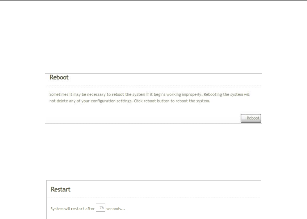
User Manual
TEW-455APBO 14dBi High Power Wireless Outdoor PoE Access Point
70
5.3.4 Reboot
This function allows the administrator to safely restart the TEW-455APBO. Click Reboot to restart the system
immediately, and the whole process will take about three minutes to complete.
The Restart page as displayed below appears during the rebooting period. If turning off the power is necessary,
please allow the restart process to be completed before turning off the system.
The System Overview page appears upon the completion of reboot.
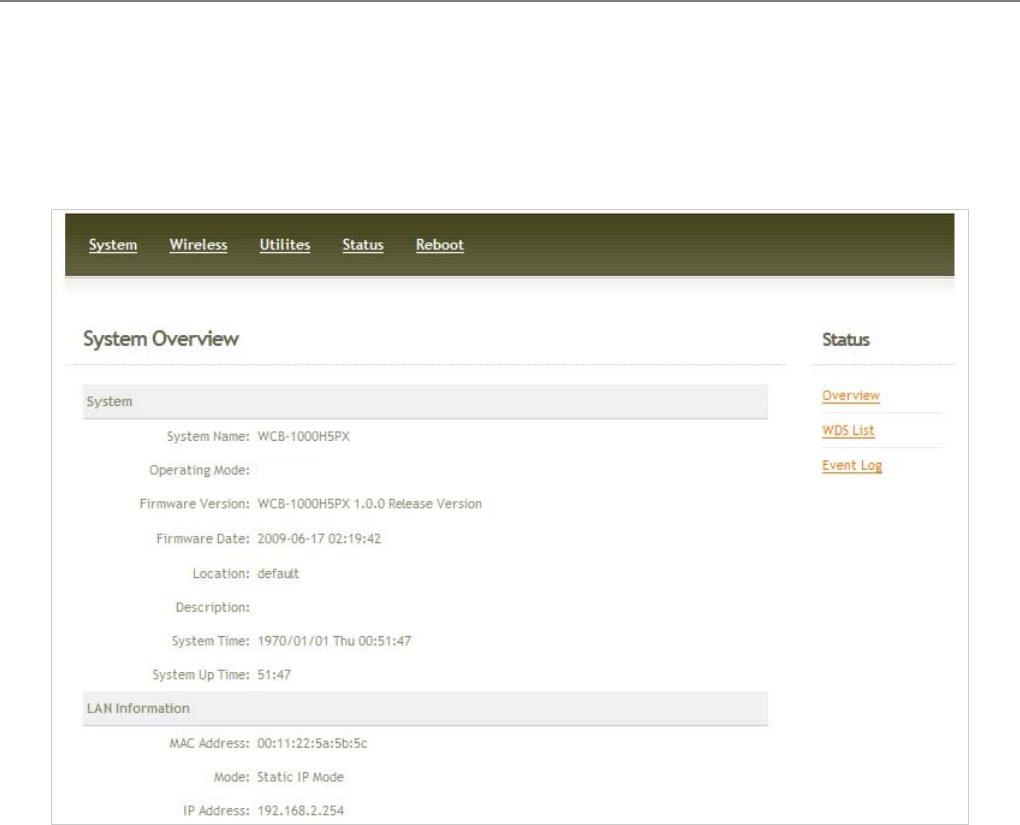
User Manual
TEW-455APBO 14dBi High Power Wireless Outdoor PoE Access Point
71
5.4 Status
Information of current system settings can be over viewed via this page; statuses of Overview, BRIDGE List, and
Event Log are displayed in this interface.
B mode
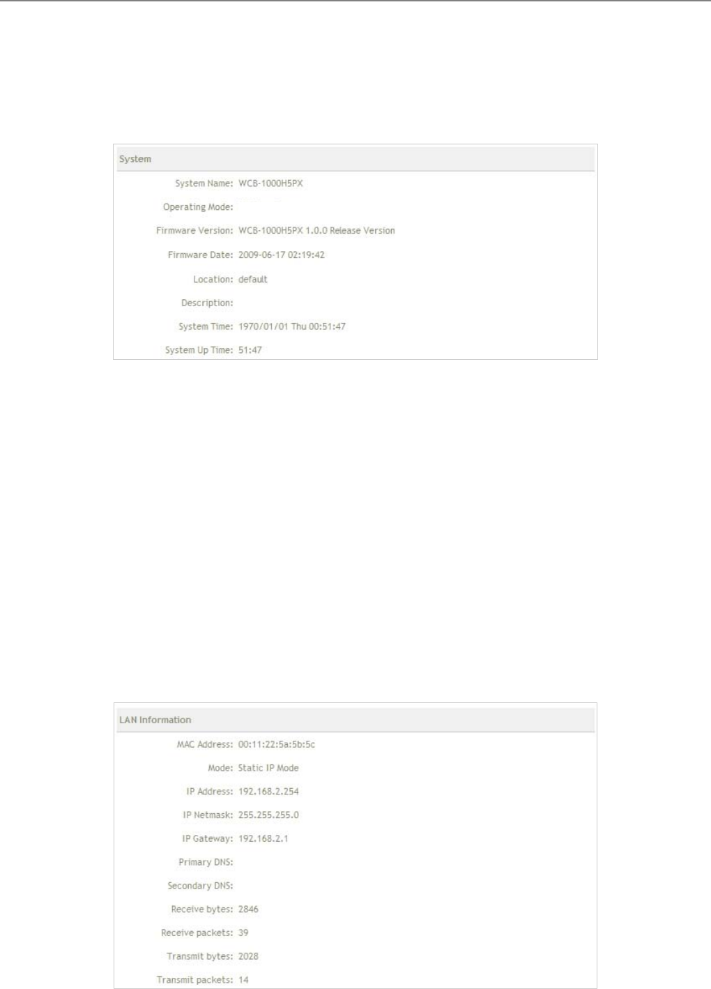
User Manual
TEW-455APBO 14dBi High Power Wireless Outdoor PoE Access Point
72
5.4.1 Overview
Detailed information on System and LAN Information can be reviewed via this page.
System : Display the information of the system.
Î System Name : The name of the system.
Î Operating Mode : The mode currently in service.
Î Firmware Version : The current firmware version installed.
Î Firmware Date : The build time of the firmware installed.
Î Location : The reminding note on the geographical location of the system. For more information, please
refer to Section 4.1.3-Management .
Î Description : Please refer to Section 4.1.3-Management .
Î System Time : The current time of the system.
Î System Up Time : The time period that the system has been in service since last boot-up.
LAN Information : Display the information of the LAN interface.
B mode

User Manual
TEW-455APBO 14dBi High Power Wireless Outdoor PoE Access Point
73
Î MAC Address : The MAC address of the LAN port.
Î Mode : The current mode of the LAN port.
Î IP Address : The IP address of the LAN port.
Î IP Netmask : The IP netmask of the LAN port.
Î IP Gateway : The gateway IP address of the LAN port.
Î Primary DNS : The current primary DNS server of the system.
Î Secondary DNS : The current secondary DNS server of the system.
Î Receive bytes :The current receive bytes of the LAN port.
Î Receive packets : The current receive packets of the LAN port.
Î Transmit bytes : The current transmit bytes of the LAN port.
Î Transmit packets : The current transmit packets of the LAN port.
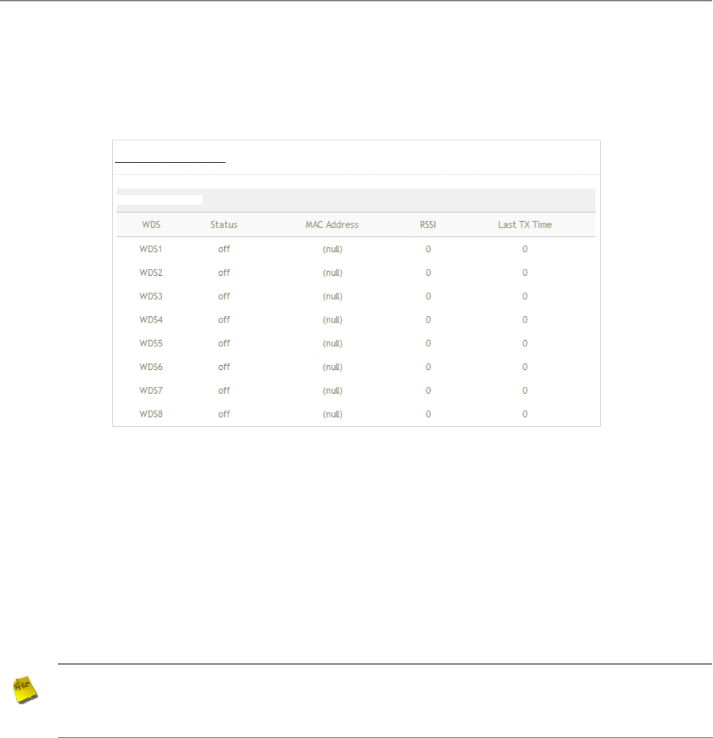
User Manual
TEW-455APBO 14dBi High Power Wireless Outdoor PoE Access Point
74
5.4.2 BRIDGE List
The administrator can obtain detailed Information such as BRIDGE, Status, MAC Address, RSSI, and Last Tx Time
of all BRIDGE link via this page.
BRIDGE : BRIDGE which the device is linked with.
Status : Display BRIDGE status.
MAC address : Display MAC address of BRIDGE peer.
RSSI : Indicate the RSSI of the respective BRIDGE linked.
Last TX time : Indicate the last receive packet of the respective BRIDGE linked.
Note :
If RSSI display 0, you need check BRIDGE configuration. Verify MAC Address, Channel and Security
type is the same; also adjust system's antenna angle. When BRIDGE link used on long distance, you
need to adjust Transmit Rate Control, Slot Time and ACK/CTS Timeout.
Brid
g
e Link Status
Brid
g
e Link Status

User Manual
TEW-455APBO 14dBi High Power Wireless Outdoor PoE Access Point
75
5.4.3 Event Log
The reported system events can be reviewed here.
Date/ Time: The date and time when the event occurred.
Hostname: The name of the host which records the event. It helps the administrator identify the source of the
reported events.
Process name (with square brackets): Indicate the process with which the specific event is associated.
Description: Description of the event.
Click Refresh button to renew the log, or click Clear button to clear all the record.
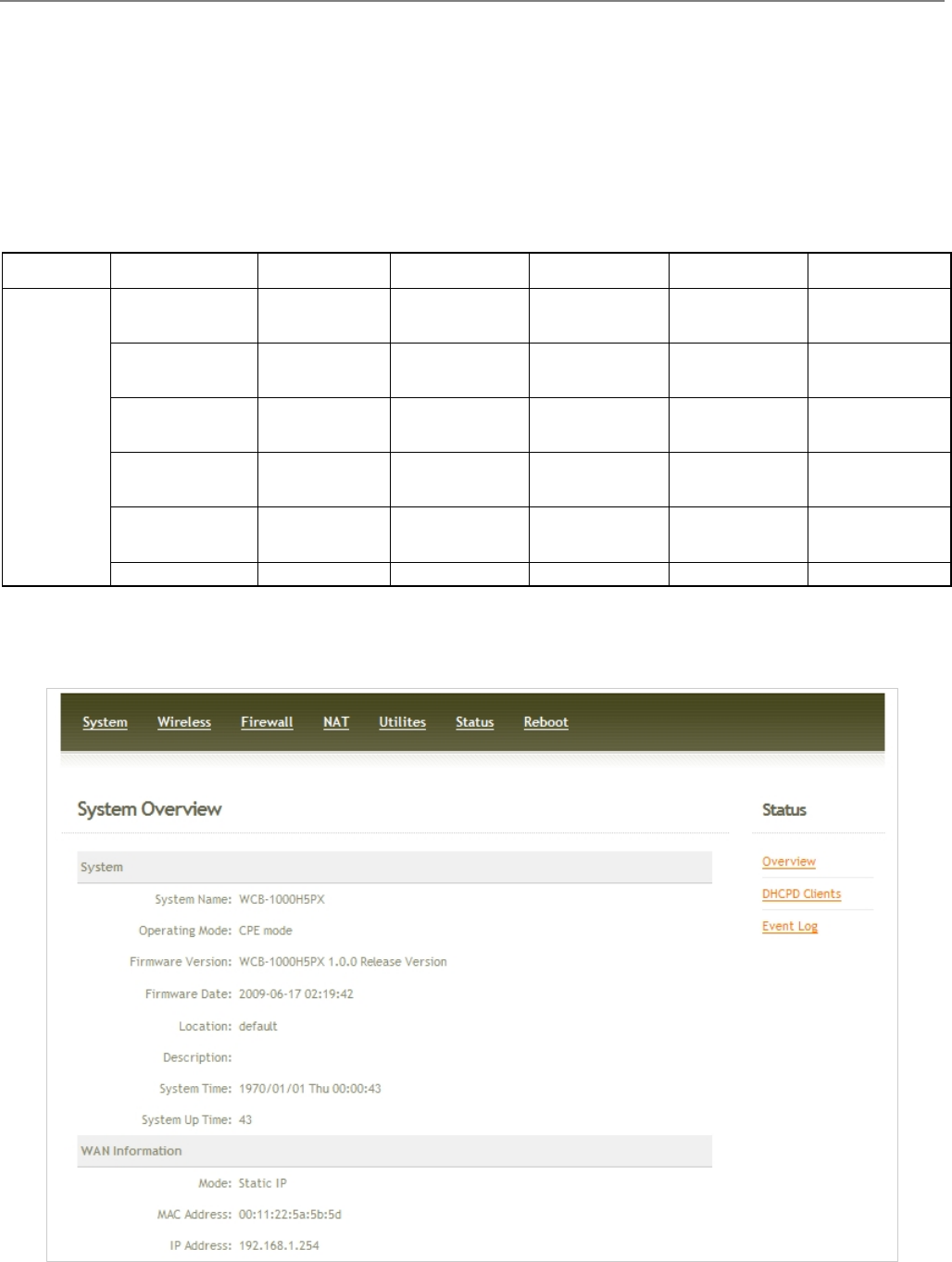
User Manual
TEW-455APBO 14dBi High Power Wireless Outdoor PoE Access Point
76
Chapter 6. CPE Mode Configuration
When CPE mode is activated, the system can be configured as a CPE. This section provides information in
configuring the CPE mode with graphical illustrations. TEW-455APBO provides functions as stated below where
they can be configured via a user-friendly web based interface.
OPTION System Wireless Firewall NAT Utilities Status
Operating
Mode General
Settings IP Rule Setup Virtual Server Profiles
Settings System
Overview
WAN Advanced
Settings MAC Rule
Setup DMZ Firmware
Upgrade DHCP Clients
LAN Site Survey Ping Utility Event Log
Management Reboot
Time Server
Functions
SNMP
Table 6-1: CPE Mode Functions
Figure 6-1: CPE Mode Main Page
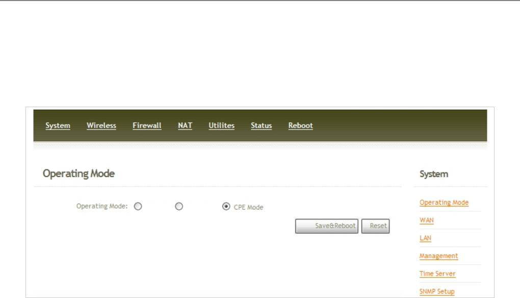
User Manual
TEW-455APBO 14dBi High Power Wireless Outdoor PoE Access Point
77
6.1 System
This section provides information in configuring the following functions: Operating Mode, WAN Setup, LAN Setup,
Management, Time Server, SNMP Setup
6.1.1 Operating Mode
TEW-455APBO supports three operation modes; BS mode , BRIDGE mode and CPE mode. The administrator can
set the desired mode via this page, and then configure the system according to their deployment needs.
9 BS Mode : Check BS Mode button to enable BS mode, and then click “Save&Reboot” to activate the
setting.
9 BRIDGE Mode : Check B Mode button to enable Bridge mode, and then click “Save&Reboot” to activate
the setting.
9 CPE Mode : Check CPE Mode button to enable CPE mode, and then click “Save&Reboot” to activate the
setting.
BS Mode B Mode
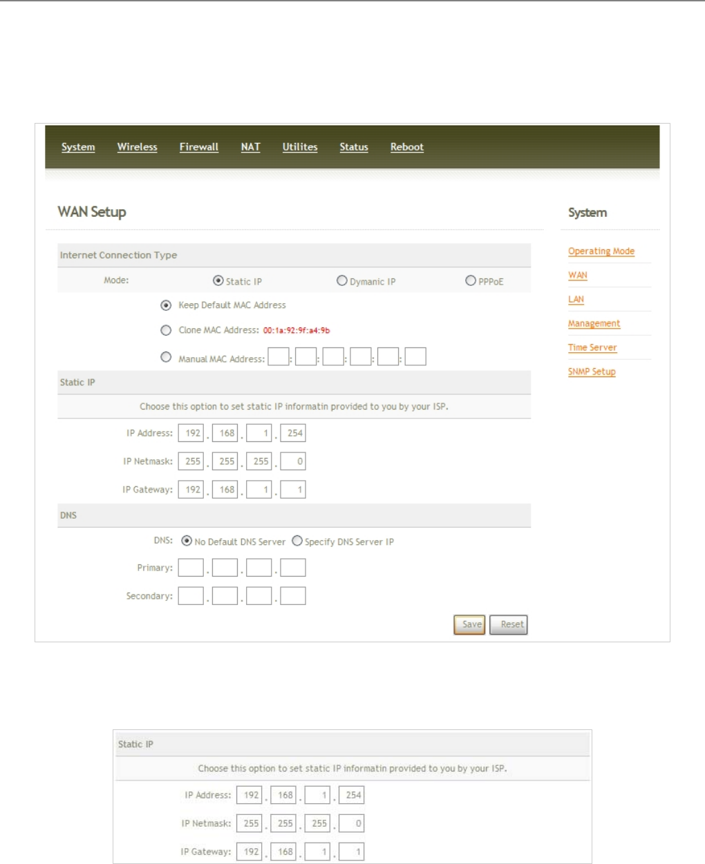
User Manual
TEW-455APBO 14dBi High Power Wireless Outdoor PoE Access Point
78
6.1.2 WAN Setup
Here is instruction for how to setup the WAN. Please click on System -> WAN and follow the below setting.
Mode : Check “Static IP”, “Dynamic IP” and “PPPoE” button as desired to set up the system IP of WAN port.
Î Static IP : The administrator can manually setup the WAN IP address when static IP is available/ preferred.
9 IP Address : The IP address of the WAN port; default IP address is 192.168.1.254
9 IP Netmask : The Subnet mask of the WAN port; default Netmask is 255.255.255.0
9 IP Gateway : The default gateway of the WAN port; default Gateway is 192.168.1.1
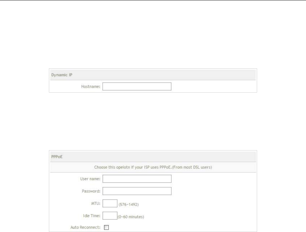
User Manual
TEW-455APBO 14dBi High Power Wireless Outdoor PoE Access Point
79
Î Dynamic IP : This configuration type is applicable when the WCB1000H5PX/ WCB1010H5PX is
connected to a network with the presence of a DHCP server; all related IP information will be provided by
the DHCP server automatically. If the IP Address do not assigned from DHCP server, the system need
manual connect to DHCP server. Please refer to Section 6.6.2-Overview (WAN Information)
9 Hostname : The Hostname of the WAN port
Î PPPoE : This configuration type is applicable when the WCB1000H5PX/ WCB1010H5PX is connected to
a network with the presence of a PPPoE server.
9 User Name : Enter User Name for PPPoE connection
9 Password : Enter Password for PPPoE connection
9 MTU : MTU stands for Maximum Transmission Unit. For PPPoE connections, you may need to set
the MTU setting in order to work correctly with your ISP. Default is 1492 bytes.
9 Idle Time : The time of inactivity before disconnecting your PPPoE session. Enter an Idle Time (in
minutes) to define a maximum period of time for which the Internet connect is maintained during
inactivity. If the connection is inactive for longer than the defined Idle Time, then the connection will be
dropped.
9 Auto Reconnect : Click Auto Reconnect button, the system will be auto reconnect with PPPoE
server through WAN port. If unclick this button, the system need manual connect to PPPoE server.
Please refer to Section 6.6.2-Overview (WAN Information)
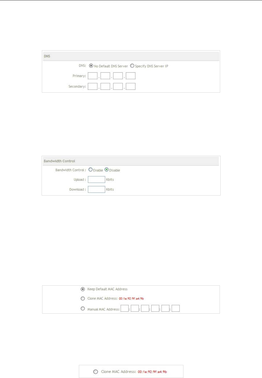
User Manual
TEW-455APBO 14dBi High Power Wireless Outdoor PoE Access Point
80
DNS : Check either “No Default DNS Server” or “Specify DNS Server IP” button as desired to set up the
system DNS.
Î Primary : The IP address of the primary DNS server.
Î Secondary : The IP address of the secondary DNS server.
Bandwidth : The administrator can control download and upload of bandwidth.
Î Upload : Enter 256 to 8192 digital number, the unit is Kbits
Î Download : Enter 256 to 8192 digital number, the unit is Kbits
MAC Address Clone : The MAC address is a 12-digit code assigned to a unique piece of hardware for
identification, like a social security number. Some ISPs require you to register a MAC address in order to
access the Internet. If you do not wish to re-register the MAC address with your ISP, you may assign the MAC
address you have currently registered with your ISP to the system using the MAC Address Clone feature.
Î Keep Default MAC Address : Keep the default MAC address of WAN port on the system.
Î Clone MAC Address : If you want to clone the MAC address of the PC you are currently using go
configure the system, then click the Clone MAC Address button. The system will automatically detect
your PC's MAC address.

User Manual
TEW-455APBO 14dBi High Power Wireless Outdoor PoE Access Point
81
Note : The Clone MAC Address field will display MAC address of the PC you are connected with the
system currently.
Î Manual Address : Enter the MAC address registered with your ISP.
Change these settings as described here and click Save button to save your changes. Click Reboot button to
activate your changes
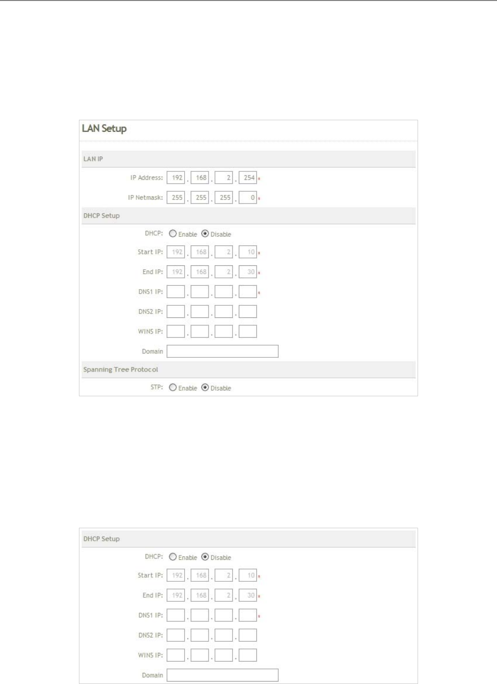
User Manual
TEW-455APBO 14dBi High Power Wireless Outdoor PoE Access Point
82
6.1.3 LAN Setup
Here is instruction for how to setup the local IP Address and Netmask. Please click on
System -> LAN and follow the below setting.
LAN IP : The administrator can manually setup the LAN IP address.
9 IP Address : The IP address of the LAN port; default IP address is 192.168.2.254
9 IP Netmask : The Subnet mask of the LAN port; default Netmask is 255.255.255.0
DHCP Setup : Devices connected to the system can obtain an IP address automatically when this service is
enabled.
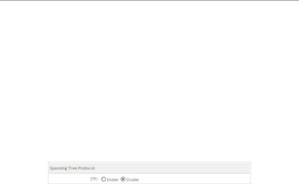
User Manual
TEW-455APBO 14dBi High Power Wireless Outdoor PoE Access Point
83
Î DHCP : Check Enable button to activate this function or Disable to deactivate this service.
Î Start IP / End IP: Specify the range of IP addresses to be used by the DHCP server when assigning IP
address to clients.
Î DNS1 IP : Enter IP address of the first DNS server; this field is required.
Î DNS2 IP : Enter IP address of the second DNS server; this is optional.
Î WINS IP : Enter IP address of the Windows Internet Name Service (WINS) server; this is optional.
Î Domain : Enter the domain name for this network.
Spanning Tree Protocol
The spanning tree network protocol provides a loop free topology for any bridged LAN. The Spanning Tree
Protocol, which is also referred to as STP, is defined in the IEEE Standard 802.1d.
Change these settings as described here and click Save button to save your changes. Click Reboot button to
activate your changes
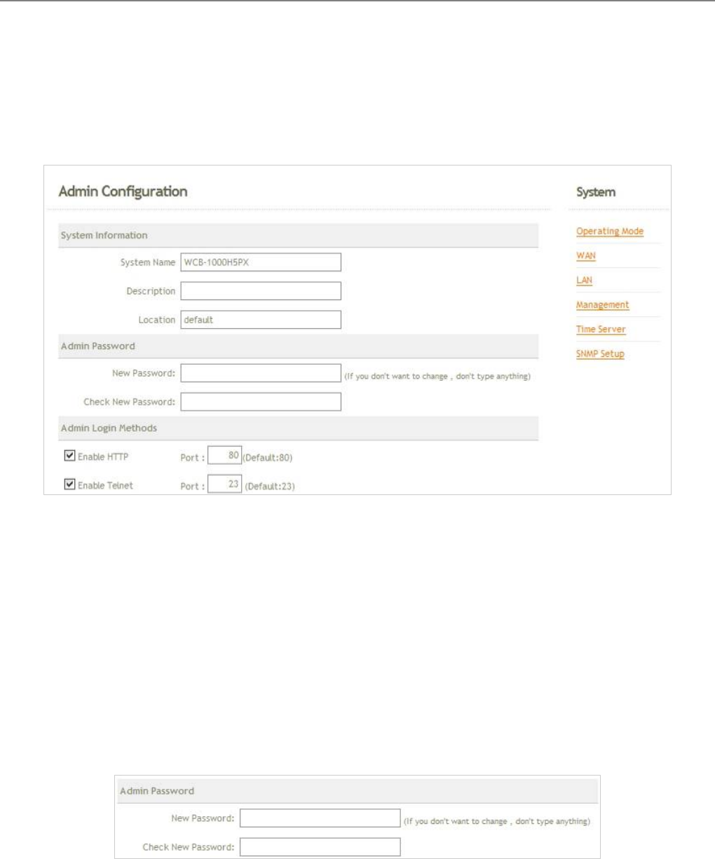
User Manual
TEW-455APBO 14dBi High Power Wireless Outdoor PoE Access Point
84
6.1.4 Management
The administrator can later obtain the geographical location of the system via the information configured here. The
administrator also can change system password and configure system login methods. Please click System ->
Management and follow the below settings.
System Information
Î System Name : Enter a desired name or use the default provided.
Î Description : Denote further information of the system.
Î Location : Enter related geographical location information of the system; administrator/manager will be
able to locate the system easily.
Admin Password : The admin manager can change its respected password. Enter the new password, and
then verify the new password in the Check New Password filed. Click Save button to activate the new
password.
Î New Password : Please input the new password of administrator.
Î Check New Password : Please input again the new password of administrator.
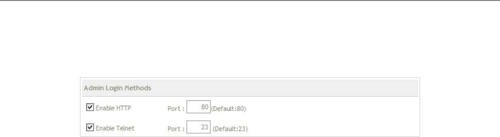
User Manual
TEW-455APBO 14dBi High Power Wireless Outdoor PoE Access Point
85
Admin Login Methods : The admin manager can enable or disable system login methods, it also can change
services port. Click Save button to activate the admin login methods.
Î Enable HTTP : Select Enable HTTP to activate HTTP Service
Î HTTP Port : Please input 1 ~ 65535 value to set HTTP Port; default value is 80
Î Enable Telnet : Select Enable HTTP to activate HTTP Service
Î Telnet Port : Please input 1 ~ 65535 value to set HTTP Port; default value is 23
Change these settings as described here and click Save button to save your changes. Click Reboot button to
activate your changes
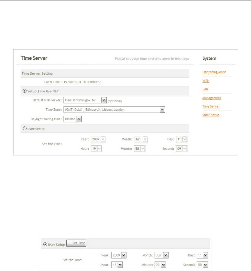
User Manual
TEW-455APBO 14dBi High Power Wireless Outdoor PoE Access Point
86
6.1.5 Time Server
System time can be configured via this page where manual setting and NTP server configuration are both
supported.
Local Time : Display the current time of the system.
Setup Time Use NTP : Enable Network Time Protocol, NTP, to synchronize the system time with NTP server.
Î Default NTP Server : Select the NTP Server from the drop-down list.
Î Time Zone : Please set a time zone from where the accurate time can be supplied, (GMT+08:00) Taipei
for example.
Î Daylight saving time : Enable Daylight saving time from where the accurate time needed.
User Setup : Enable User Setup and Click Set Time button; the system time can be configured manually.
Î Set Time : Click Set Time button, the Time field should be changed automatically.
Î Set the time : Select the appropriate Year, Month, Day, Hour, Minute and Second from the drop-down
list.
Change these settings as described here and click Save button to save your changes. Click Reboot button to
activate your changes
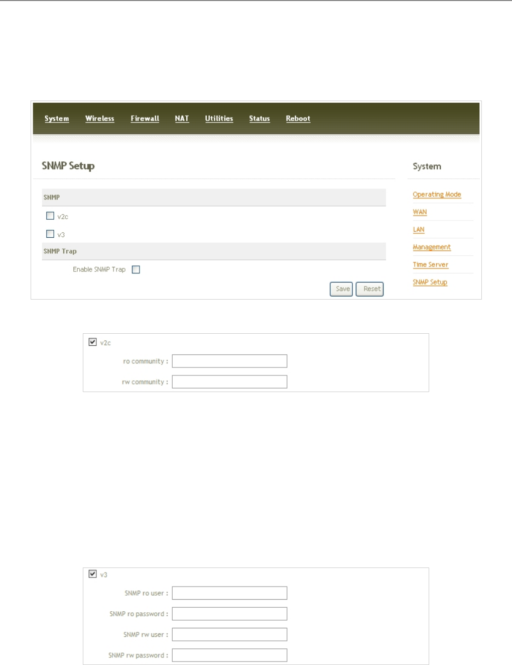
User Manual
TEW-455APBO 14dBi High Power Wireless Outdoor PoE Access Point
87
6.1.6 SNMP Setup
SNMP is an application-layer protocol that provides a message of format for communication between SNMP
managers and agents. By enabling SNMP function, the administrator can obtain the system information remotely.
v
2
c :
C
h
e
ck
v
2
c
b
utton to activate SNMP v2c agent or unchecked to deactivate this function.
Î ro community : Enter the community strings that allows read-only access to the system's SNMP
information.
Î rw community : Enter the community strings that allows read/write access to the system's SNMP
information.
v3 : Check v3 button to activate SNMP v3 agent or unchecked to deactivate this function. SNMPv3 supports
the highest available levels of security for SNMP communication.
Î SNMP ro user : Enter the community strings that allows read-only access to the system's SNMP
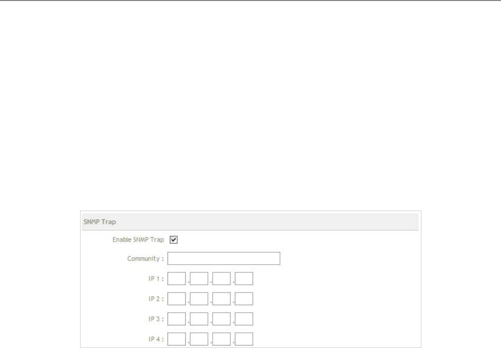
User Manual
TEW-455APBO 14dBi High Power Wireless Outdoor PoE Access Point
88
information.
Î SNMP ro password : Enter the password that allows read-only access to the system's SNMP information.
Î SNMP rw user : Enter the community strings that allows read/write access to the system's SNMP
information.
Î SNMP rw password : Enter the password that allows read/write access to the system's SNMP
information.
SNMP Trap : Events on cold start, interface up & down, and association & disassociation can be reported via
this function to an assigned server.
Î Community : Enter the community strings required by the remote host computer that will receive trap
messages or notices send by the system.
Î IP : Enter the IP address of the remote host computer that will receive the trap messages.
Change these settings as described here and click Save button to save your changes. Click Reboot button to
activate your changes
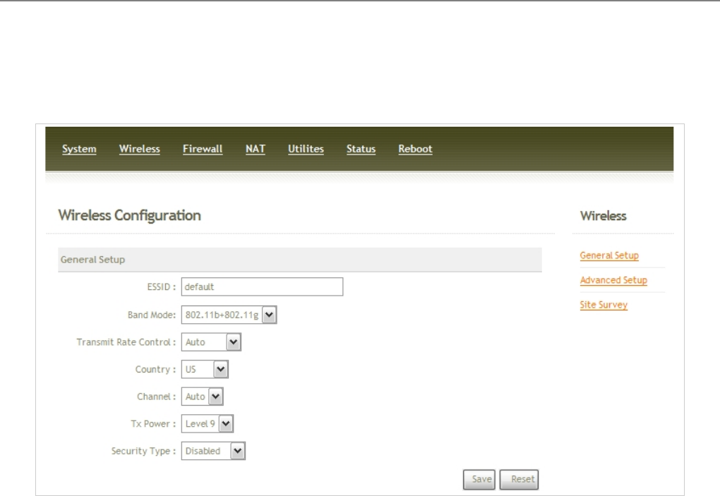
User Manual
TEW-455APBO 14dBi High Power Wireless Outdoor PoE Access Point
89
6.2 Wireless
This section will guide users through wireless setting for TEW-455APBO to associate with its up link BS.
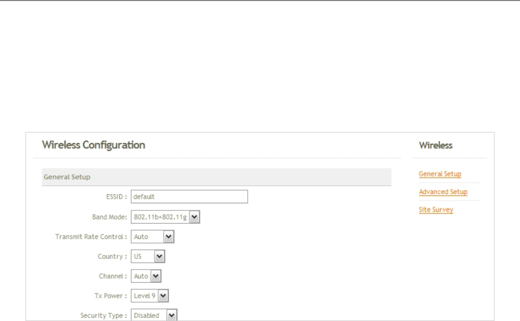
User Manual
TEW-455APBO 14dBi High Power Wireless Outdoor PoE Access Point
90
6.2.1 General Setup
The administrator can change the data transmission, channel and output power settings for the system. Please
click on Wireless -> General Setup and follow the below setting.
ESSID : Assign Service Set ID for the wireless system.
Band Mode : Select an appropriate wireless band; bands available are 801.11b, 802.11g and
802.11b+802.11g.
Transmit Rate Control : Select the desired rate from the drop-down list; the options are auto or ranging from
1 to 54Mbps for 802.11g and 802.11b/g modes, or 1 to 11Mbps for 802.11b mode.
Country : Select the desired country code from the drop-down list; the options are US, ETSI and Japan.
Channel : The channel range will be changed by selecting different country code. The channel range from 1 to
11 for US country code, or 1 to 13 for ETSI country code, or 1 to 14 for Japan.
Tx Power : You can adjust the output power of the system to get the appropriate coverage for your wireless
network. Select the LEVEL 1 to LEVEL 9 you needed for your environment. If you are not sure of which
setting to choose, then keep the default setting, LEVEL 9.
Security Type : Select the desired security type from the drop-down list; the options are WEP, WPA-PSK and
WPA2-PSK.
Î Disable : Data are unencrypted during transmission when this option is selected.
Î WEP : WEP, Wired Equivalent Privacy, is a data encryption mechanism based on a 64-bits , 128-bits or
152-bits shared key algorithm. Select WEP as the security type from drop-down list as desired. The WEP
key configured here must be exactly the same as the key on the base station that this system is
associated with.
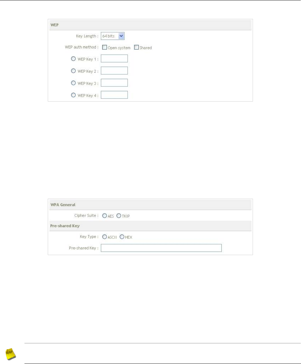
User Manual
TEW-455APBO 14dBi High Power Wireless Outdoor PoE Access Point
91
9 Key Length : Select the desire option are 64 bits, 128 bits or 152 bits from drop-down list.
9 WEP auth Method : Enable the desire option among Open system or Shared.
9 WEP Key # : Select key index is used to designate the WEP key during data transmission. Enter HEX
format WEP key value; the system support up to 4 sets of WEP keys.
Î WPA-PSK (or WPA2-PSK) : WPA (or WPA2)Algorithms, allows the system accessing the network by
using the WPA-PSK protected access.
9 Cipher Suite : Check on the respected button to enable either AES or TKIP cipher suites; default is
TKIP.
9 Key Type : Check on the respected button to enable either ASCII or HEX format for the Pre-shared
Key.
9 Pre-shared Key : Enter the information for pre-shared key; the format of the information shall
according to the key type selected.
Note : Pre-shared key can be either entered as a 256-bit secret in 64 HEX digits format, or 8 to 63 ASCII
characters.
Change these settings as described here and click Save button to save your changes. Click Reboot button to
activate your changes.
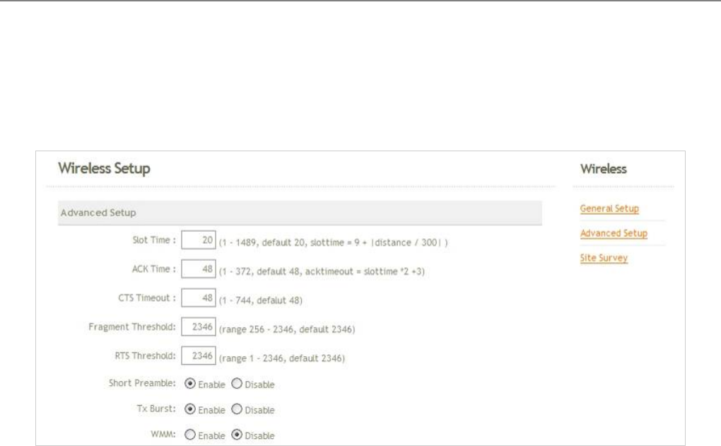
User Manual
TEW-455APBO 14dBi High Power Wireless Outdoor PoE Access Point
92
6.2.2 Advanced Setup
The administrator can change the Slot Time, ACK/CTS Timeout, RTS threshold and fragmentation threshold
settings for the system. Please click on Wireless -> Advanced Setup and follow the below setting.
Slot Time : Enter the desired slot time for the BRIDGE.
ACK Timeout : The time interval for waiting the “ ACKnowledgment frame”. If the ACK is not received within
that timeout period then the packet will be re-transmitted. Higher ACK Timeout will decrease the packet lost,
but the throughput will be growing worse.
CTS Timeout : Enter the desired CTS timeout for the BRIDGE.
Fragment Threshold : The value specifies the maximum size of packet allowed before data is fragmented into
multiple packets. Please use this value to tune the wireless connection if lots of retransmission happens. Enter
a value ranging from 256 to 2346.
RTS Threshold : Tuning the Request to Send, RTS threshold will help the system control its access to
medium and alleviate the hidden node problem. Enter a value ranging from 1 to 2346.
Short Preamble : The short preamble provides 56-bit Synchronization field to improve WLAN transmission
efficiency. Check Enable button for using Short Preamble, and Disable for using the Long Preamble, 128-bit
Synchronization field, option.
Tx Burst : Click Enable button for using Tx Burst, and Disable for non using Tx Burst.
WMM : Select Enable, the packets with QoS WMM will has higher priority.
Change these settings as described here and click Save button to save your changes. Click Reboot button to
activate your changes.
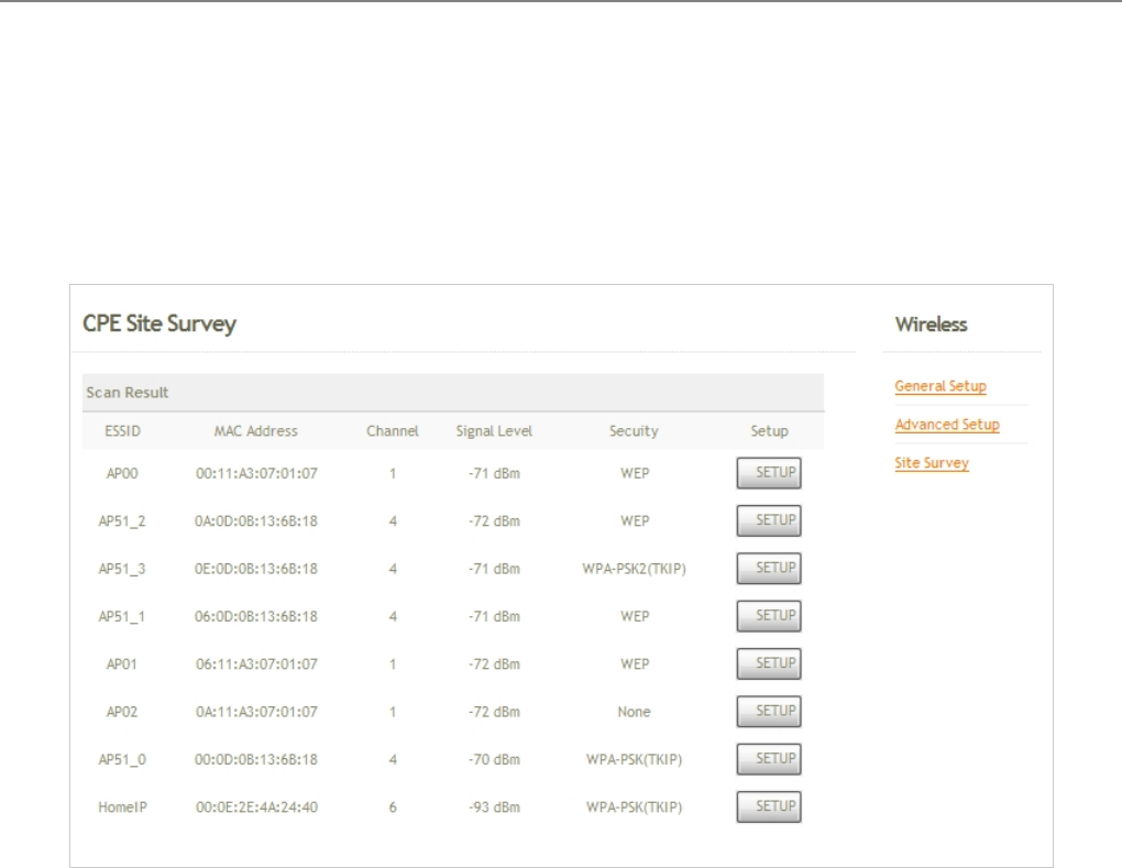
User Manual
TEW-455APBO 14dBi High Power Wireless Outdoor PoE Access Point
93
6.2.3 Site Survey
Base station located around the system can be found via the scan function. The administrator can then select a
desired BS to be associated with via this page. Please click on
Wireless -> Site Survey.
SSID : Service Set ID of the BS or repeater found around the system.
MAC Address : MAC address of the respected BS.
Channel : The channel number currently used by the respective BS.
Signal : The signal strength of the respected BS.
Security : Security type enabled by the respected BS.
Setup : Click Setup to configure settings for associating with the respected BS.
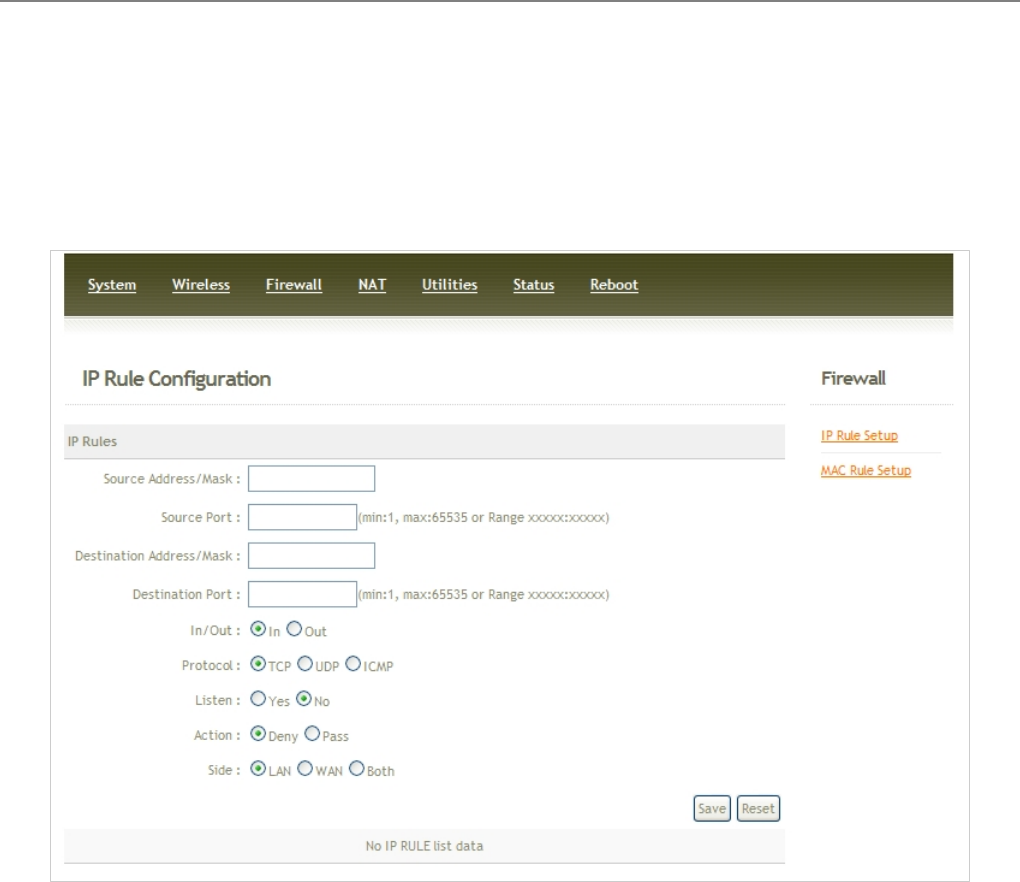
User Manual
TEW-455APBO 14dBi High Power Wireless Outdoor PoE Access Point
94
6.3 Firewall
Current firewall functions supported are IP filter and MAC filter. The system's firewall enhances the security of your
network, you can also enable a variety of filters to further protect your network.
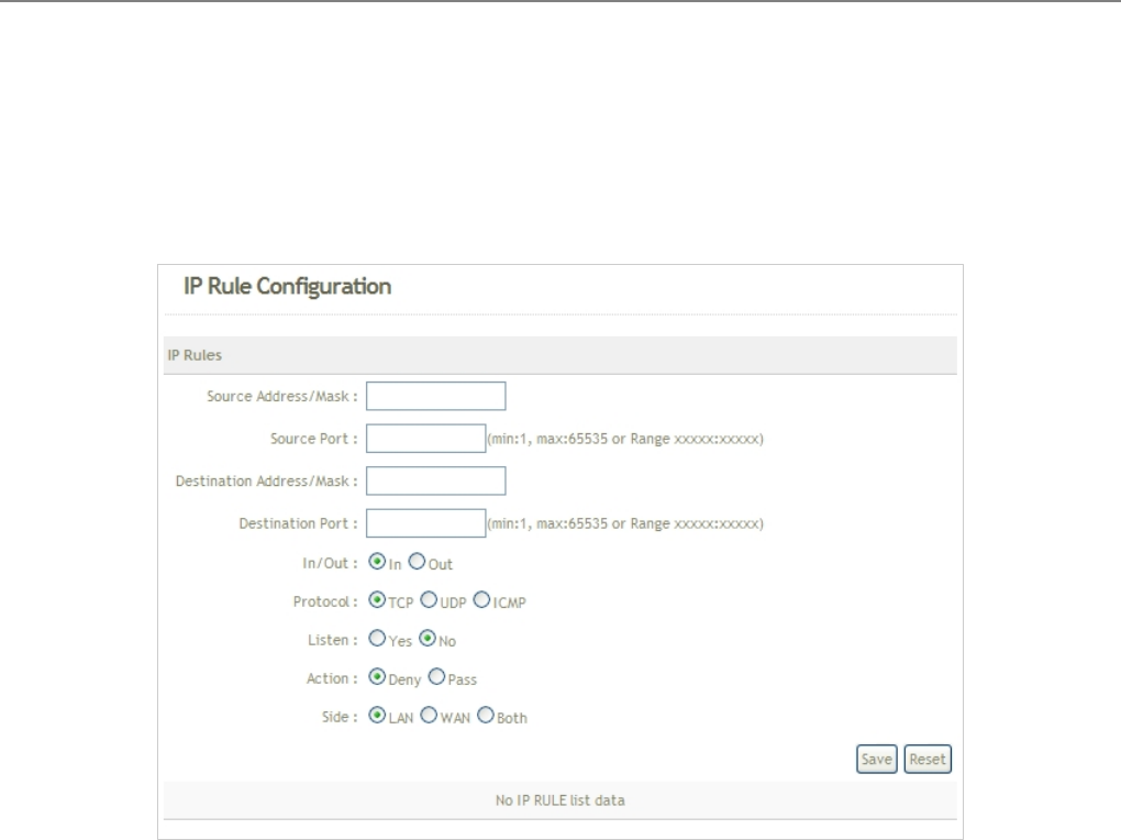
User Manual
TEW-455APBO 14dBi High Power Wireless Outdoor PoE Access Point
95
6.3.1 IP Rule Setup
The administrator can setting IP Filter via this page, Please click on Firewall -> IP Rule Setup and follow the below
setting.
Source Address/Mask : Enter the desired source IP address and netmask; the mask must be a plain number,
i.e. 192.168.2.10/32
Source Port : The source port(s) required for this rule. A single port may be given, or a range may be given as
start:end , which will match all ports from start to end, inclusive.
Destination Address/Mask : Enter the desired destination IP address and netmask; the mask must be a plain
number, i.e. 192.168.1.10/32
Destination Port : The destination port(s) required for this rule. A single port may be given, or a range may be
given as start:end , which will match all ports from start to end, inclusive.
In/Out : This option used for specialized packet alteration. The system support In (INPUT : for packets coming
into the interface itself) or Out (FORWARD : for altering packets being routed through the interface)
Protocol : This option allows you to select protocol type. The system support TCP, UDP or ICMP.
Listen : Enable Yes to match TCP packets only with the SYN flag.
Active : Enter Deny to DROP specialized packet; Pass to ACCET the specialized packet
Side : Select specified interface via which a packet was received.
Save : Click Save button to activate the new creation.
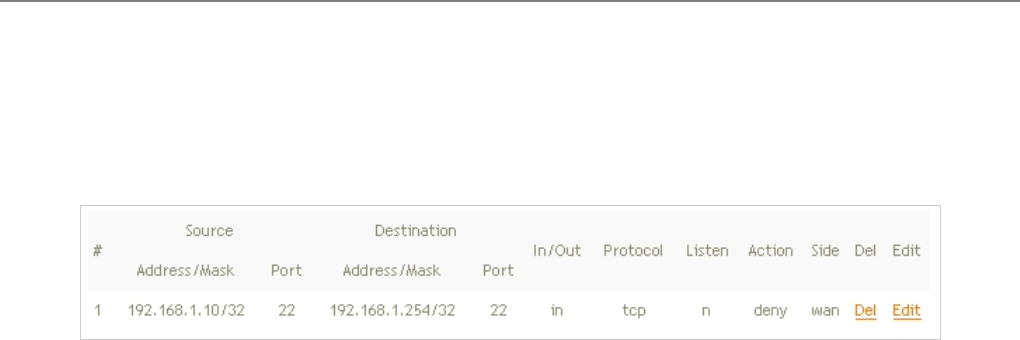
User Manual
TEW-455APBO 14dBi High Power Wireless Outdoor PoE Access Point
96
Reset : Click Reset button to clear configuration field.
There are 20 rules maximum allowed in this list.
Del : Click Del to remove desired rule.
Edit : Click Edit to edit desired rule.
Click Reboot button to activate your changes.
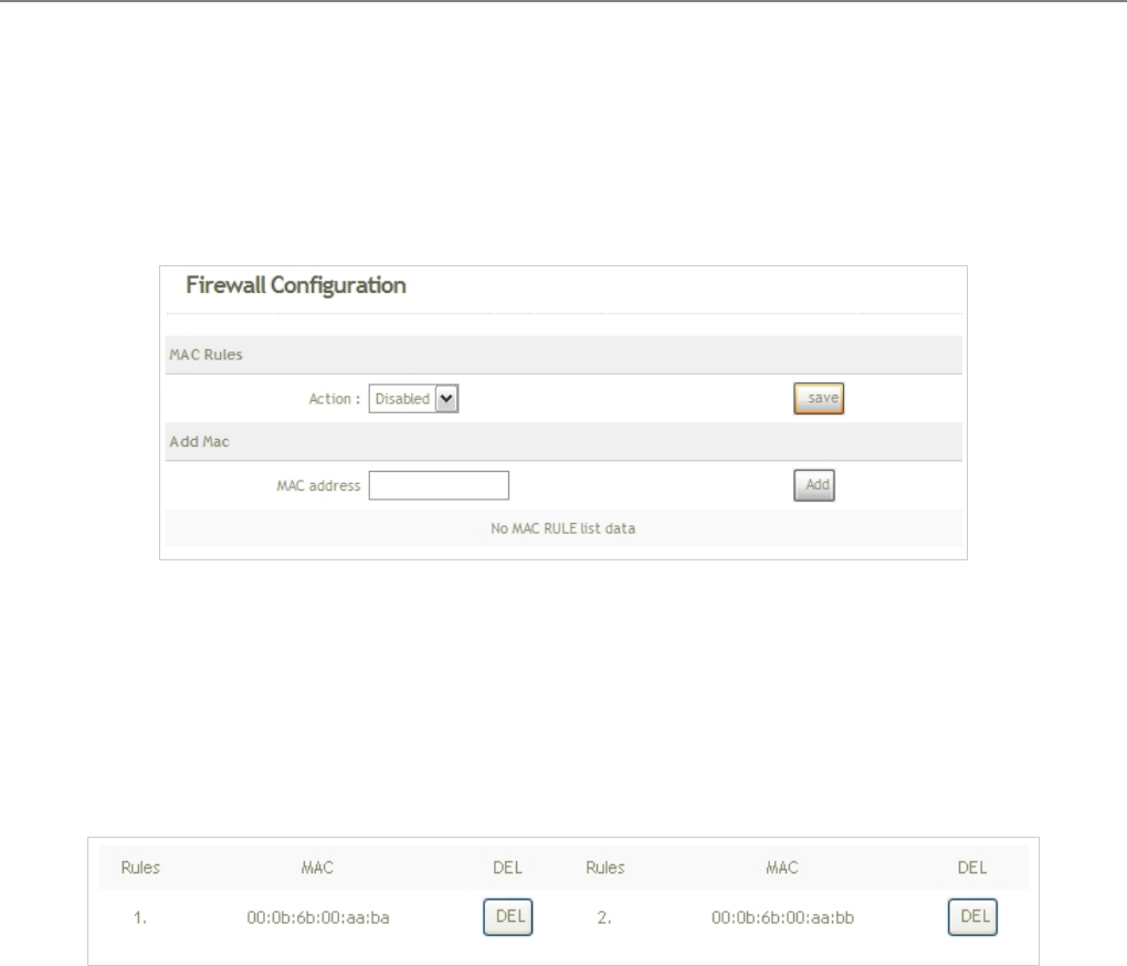
User Manual
TEW-455APBO 14dBi High Power Wireless Outdoor PoE Access Point
97
6.3.2 MAC Rule Setup
The administrator can setting MAC Filter via this page, Please click on Firewall -> MAC Rule Setup and follow the
below setting.
Action : Select the desired access control rule from the drop-down list; the options are Disable, Deny All and
Allow All.
MAC Address : Enter MAC address in this field. There are 20 rules maximum allowed in this MAC address list.
Add : Click Add button to activate the new creation.
DEL : Click DEL button to remove the rule.
Change these settings as described here and click Save button to save your changes. Click Reboot button to
activate your changes.
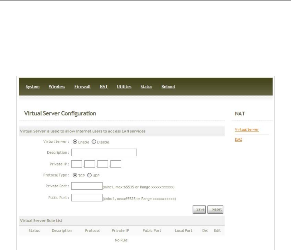
User Manual
TEW-455APBO 14dBi High Power Wireless Outdoor PoE Access Point
98
6.4 NAT
Current NAT functions supported are IP/ Port forwarding and DMZ, Demilitarized Zone. The administrator can open
a certain area in the network to the Internet for limited and controlled access for special purpose such as gaming
server or conferencing center.
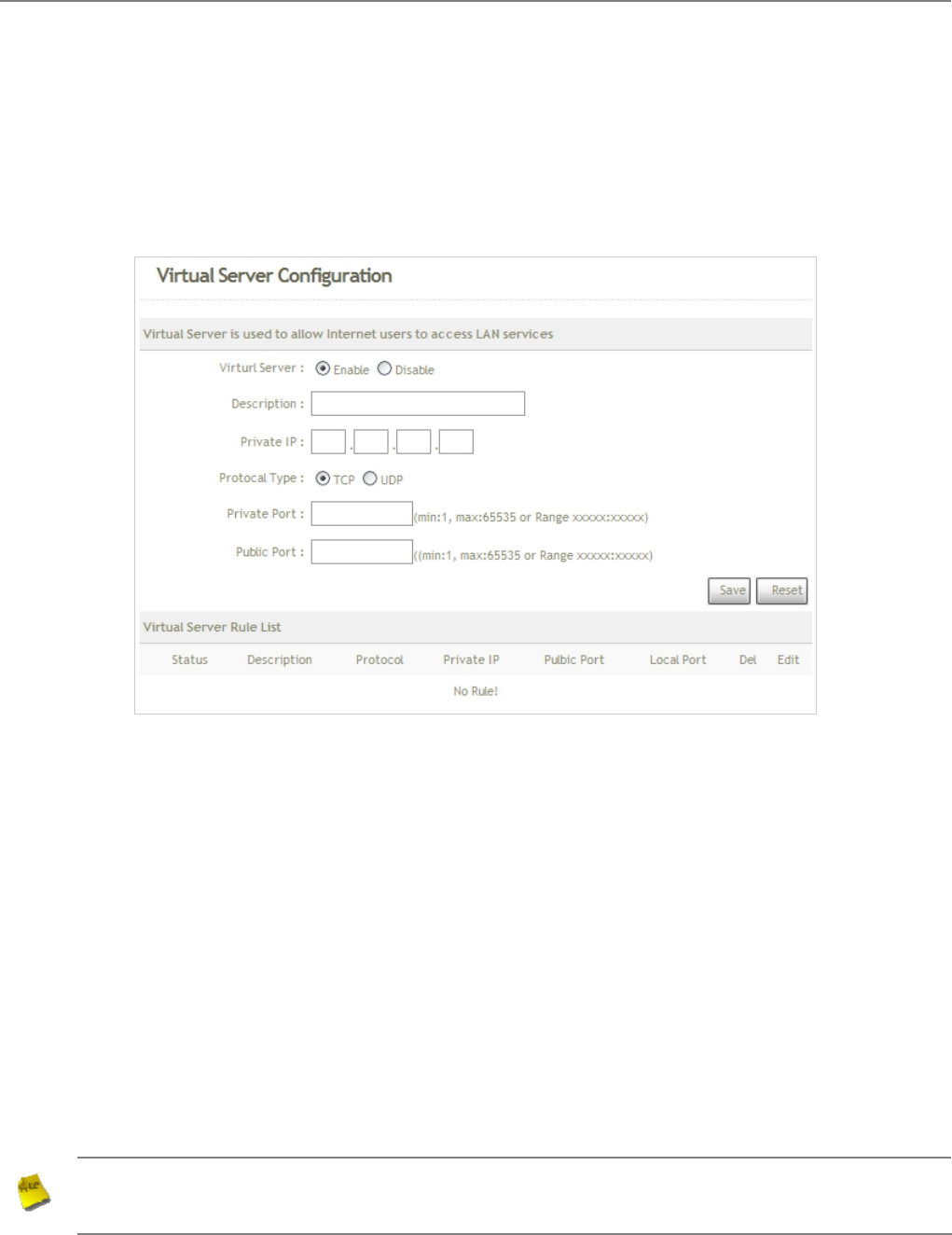
User Manual
TEW-455APBO 14dBi High Power Wireless Outdoor PoE Access Point
99
6.4.1 Virtual Server (IP/ Port Forwarding)
A certain area in the network can be exposed to the Internet in a limited and controlled way for on-line game or
video conferencing via this page. Please ensure the internal port to be used is not occupied by other applications.
Please click on NAT -> Virtual Server and follow the below setting.
Virtual Server : Check Enable button to activate this rule, and Disable to deactivate.
Description : Enter appropriate text to denote name of the Virtual server.
Private IP : The corresponding IP address of the LAN port used for the respected service. Enter the LAN IP
address of the assigned host.
Protocol Type : The communication protocol of session. Select an appropriate protocol type, either TCP or
UDP protocol.
Private Port : The private port(s) required for this rule. A single port may be given, or a range may be given as
start:end , which will match all ports from start to end, inclusive.
Public Port : The public port(s) required for this rule. A single port may be given, or a range may be given as
start:end , which will match all ports from start to end, inclusive.
Note :
The Private Port and Public Port can be different, but the port range need the same.
example : Public Port is 10 to 20, the Private Port can be 30 to 40 or other 10 ports range.
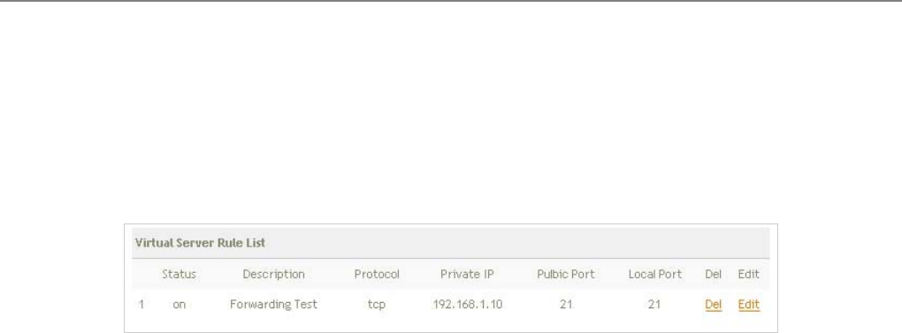
User Manual
TEW-455APBO 14dBi High Power Wireless Outdoor PoE Access Point
100
Save : Click Save button to activate the new creation.
Reset : Click Reset button to clear configuration field.
There are 20 rules maximum allowed in this Virtual Server Rule List
Del : Click Del to remove desired rule.
Edit : Click Edit to edit desired rule.
Click Reboot button to activate your changes.
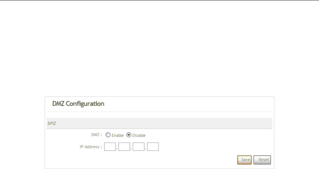
User Manual
TEW-455APBO 14dBi High Power Wireless Outdoor PoE Access Point
101
6.4.2 DMZ
The Demilitarized Zone, DMZ, allows a computer or server to be exposed to the Internet for special purpose, i.e. a
web server, where external users can access the location without authentication. Please click on NAT -> DMZ and
follow the below setting.
DMZ : Check Enable button to activate this function, and Disable to deactivate.
IP Address : Enter the IP address of the computer or server to be used as DMZ host; only one DMZ host can
be activate at any time period.
Change these settings as described here and click Save button to save your changes. Click Reboot button to
activate your changes.

User Manual
TEW-455APBO 14dBi High Power Wireless Outdoor PoE Access Point
102
6.5 Utilities
The administrator can maintain the system via this page: Profile Setting, System Upgrade, Ping Utility, and
Reboot.
6.5.1 Profile Setting
Current settings on the system can be backed up, or previous backed up settings can be restored as well as
resetting the system back to factory default can be performed via this page. Please click on Utilities -> Profile
Setting and follow the below setting.
Save Settings to PC : Click Save button to save the current system settings to a local disk, i.e. the HDD of a
local computer or Compact Disc.
Load Settings from PC : Click Browse button to search for a previously saved backup file, and then click
Upload button to upload the settings; the system will then be configured to the same settings as specified by
the backup file.
Restore To Factory Default : Click Restore button to load the factory default settings of TEW-455APBO, and
then Success Message page appears. Click Reboot button to set default configuration.

User Manual
TEW-455APBO 14dBi High Power Wireless Outdoor PoE Access Point
103
6.5.2 Firmware Upgrade
To upgrade the system firmware, click Browse to search for the new firmware file, and then click Upgrade button
to execute the upgrade process.
Note :
1. To prevent data loss during firmware upgrade, please back up the current settings before
proceeding to firmware upgrade.
2. Please restart the system after the upgrade. Do not interrupt the system, i.e. power on/off, during
the upgrading process or the restarting process as this may damage system.
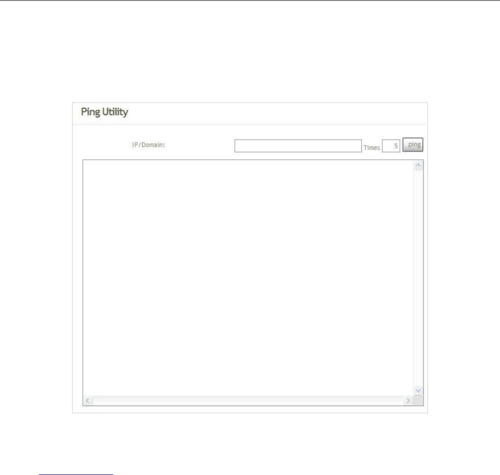
User Manual
TEW-455APBO 14dBi High Power Wireless Outdoor PoE Access Point
104
6.5.3 Ping Utility
The administrator can diagnose the network connectivity via this function.
Î IP/Domain : Enter the desired domain name or IP address of the target device for diagnosis purpose, i.e.
www.google.com, and click ping button to proceed. The ping result will be shown in the Result field.
Î Time : Enter the time for ping utility; default is 5, maximum is 50.

User Manual
TEW-455APBO 14dBi High Power Wireless Outdoor PoE Access Point
105
6.5.4 Reboot
This function allows the administrator to safely restart the TEW-455APBO. Click Reboot to restart the system
immediately, and the whole process will take about three minutes to complete.
The Restart page as displayed below appears during the rebooting period. If turning off the power is necessary,
please allow the restart process to be completed before turning off the system.
The System Overview page appears upon the completion of reboot.
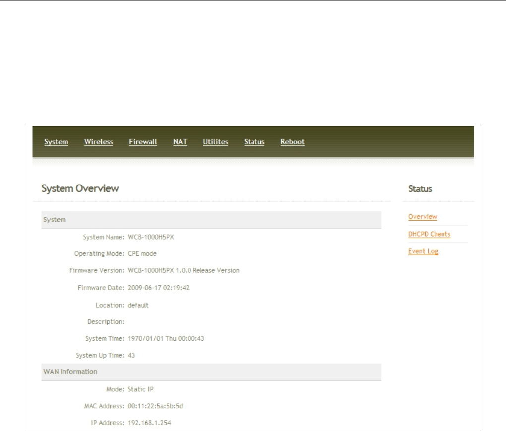
User Manual
TEW-455APBO 14dBi High Power Wireless Outdoor PoE Access Point
106
6.6 Status
Information of current system settings can be over viewed via this page; statuses of Overview, DHCP Clients, and
Event Log are displayed in this interface.
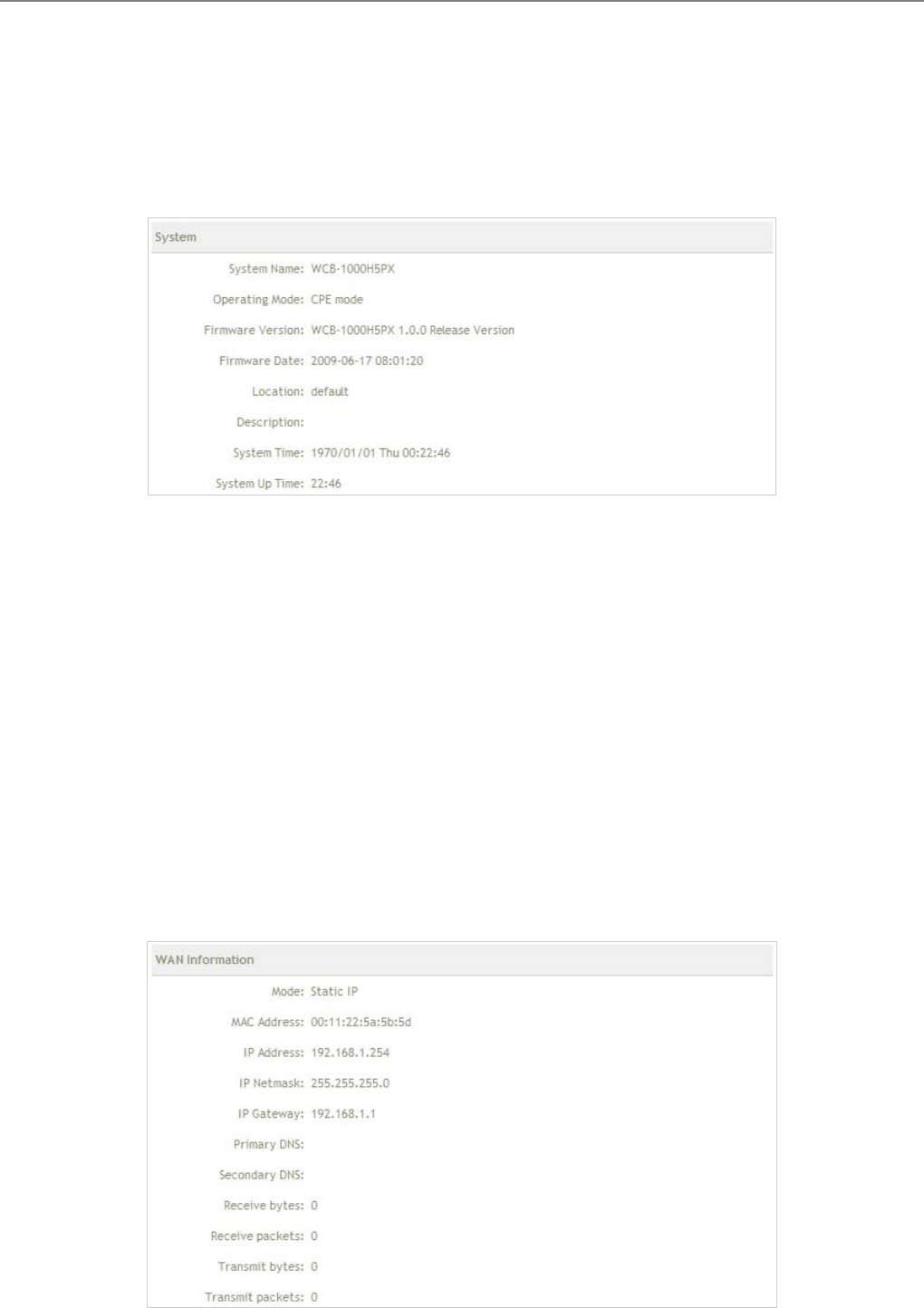
User Manual
TEW-455APBO 14dBi High Power Wireless Outdoor PoE Access Point
107
6.6.1 Overview
Detailed information on System, WAN Information, CPE Wireless Information and LAN Information can be
reviewed via this page.
System : Display the information of the system.
Î System Name : The name of the system.
Î Operating Mode : The mode currently in service.
Î Firmware Version : The current firmware version installed.
Î Firmware Date : The build time of the firmware installed.
Î Location : The reminding note on the geographical location of the system. For more information, please
refer to Section 4.1.3-Management .
Î Description : Please refer to Section 4.1.3-Management .
Î System Time : The current time of the system.
Î System Up Time : The time period that the system has been in service since last boot-up.
WAN Information : Display the information of the WAN interface.
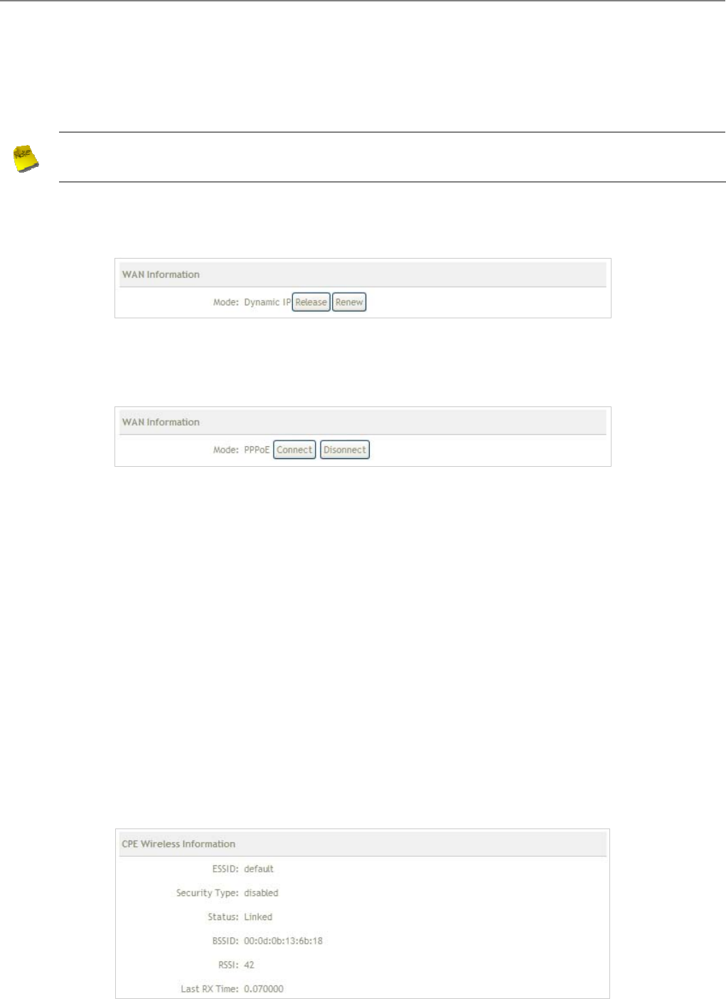
User Manual
TEW-455APBO 14dBi High Power Wireless Outdoor PoE Access Point
108
Î Mode : The current mode of the WAN port.
Note : The WAN port specified Dynamic IP, and the Release and Renew button will be show up. The
WAN port specified PPPoE, and the Connect and Disconnect button will be show up.
9 Dynamic IP : Click Release button to release IP address of WAN port, Renew button to renew IP
address through DHCP server.
9 PPPoE : Click Connect button to assigned IP address from PPPoE server. Disconnect button to
release IP address of WAN port.
Î MAC Address : The MAC address of the WAN port.
Î IP Address : The IP address of the WAN port.
Î IP Netmask : The IP netmask of the WAN port.
Î IP Gateway : The gateway IP address of the WAN port.
Î Primary DNS : The current primary DNS server of the system.
Î Secondary DNS : The current secondary DNS server of the system.
Î Receive bytes :The current receive bytes of the WAN port.
Î Receive packets : The current receive packets of the WAN port.
Î Transmit bytes : The current transmit bytes of the WAN port.
Î Transmit packets : The current transmit packets of the WAN port.
CPE Wireless Information : Display the information of the Wireless interface.
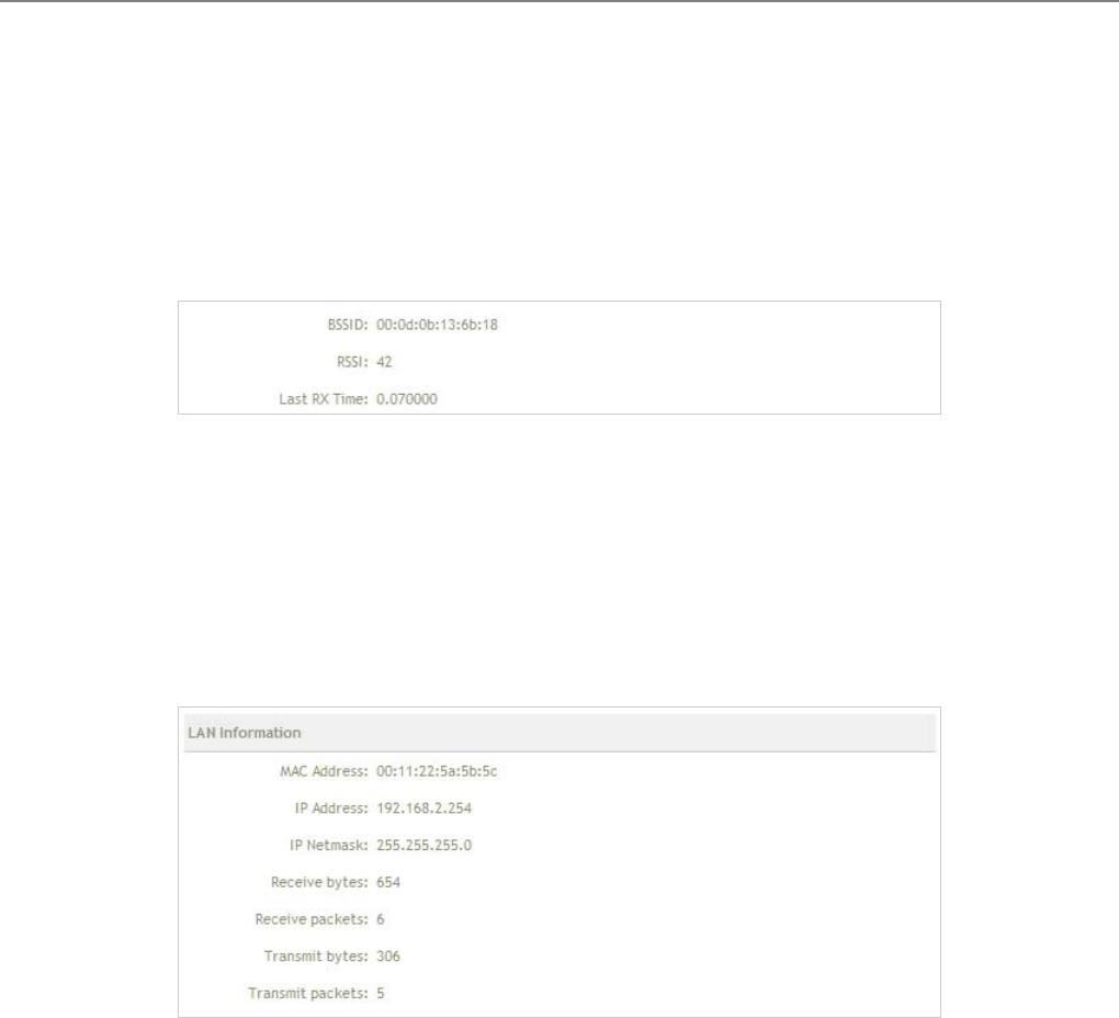
User Manual
TEW-455APBO 14dBi High Power Wireless Outdoor PoE Access Point
109
Î ESSID : Display Extended Service Set ID of the wireless currently.
Î Security : Display security type of the wireless currently.
Î Status : Display connection status of the wireless currently.
If the system associate with BS, the BSSID, RSSI and Last Tx Time will be show up.
Î BSSID : Indicate the Basic Service Set ID of the associated BS
Î RSSI : Indicate the RSSI of the associated BS.
Î Last Tx Time : Indicate the last receive packet of the associated BS
LAN Information : Display the information of the LAN interface.
Î MAC Address : The MAC address of the LAN port.
Î IP Address : The IP address of the LAN port.
Î IP Netmask : The IP netmask of the LAN port.
Î Receive bytes :The current receive bytes of the LAN port.
Î Receive packets : The current receive packets of the LAN port.
Î Transmit bytes : The current transmit bytes of the LAN port.
Î Transmit packets : The current transmit packets of the LAN port.
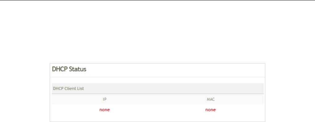
User Manual
TEW-455APBO 14dBi High Power Wireless Outdoor PoE Access Point
110
6.6.2 DHCP Clients
The administrator can obtain DHCP client's IP/MAC address via this page.
IP : The IP address assigned by DHCP server to the specific LAN device.
MAC address : The MAC address of the LAN device.
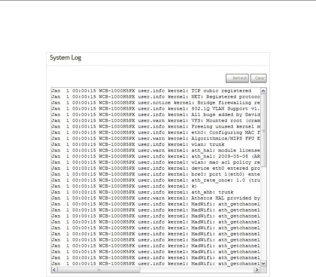
User Manual
TEW-455APBO 14dBi High Power Wireless Outdoor PoE Access Point
111
6.6.3 Event Log
The reported system events can be reviewed here.
Date/ Time: The date and time when the event occurred.
Hostname: The name of the host which records the event. It helps the administrator identify the source of the
reported events.
Process name (with square brackets): Indicate the process with which the specific event is associated.
Description: Description of the event.
Click Refresh button to renew the log, or click Clear button to clear all the record.
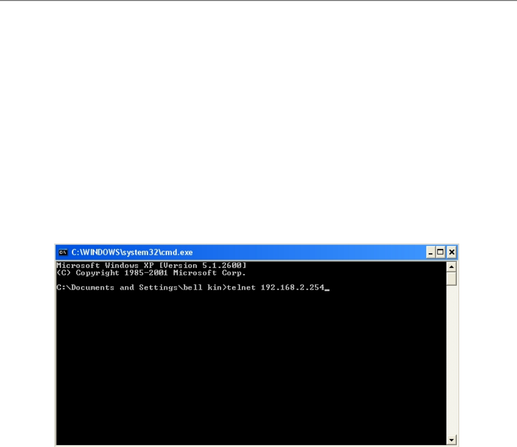
User Manual
TEW-455APBO 14dBi High Power Wireless Outdoor PoE Access Point
112
7. Command Line Interface(CLI)
The administrator can be used help, showinfo, pwinfo, set, reboot, default and password functions from Telnet
session.
7.1 Accessing the CLI with Telnet
Follow these steps to access the CLI with Telnet of Windows XP.
1. Click Start -> Run, and type “cmd” in the “Run” window. The command window appears.
2. Enter “telnet 192.168.2.254” to connect with system.
3. Enter
userna
me and
passwor
d on the
Telnet
session.
And the
comma
nd line
session
appears. The default username is “admin”, and password is “default”
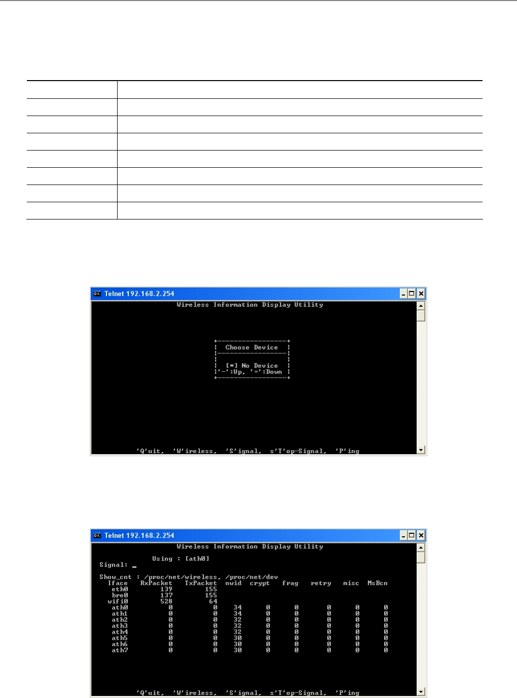
User Manual
TEW-455APBO 14dBi High Power Wireless Outdoor PoE Access Point
113
7.2 Using the CLI
After accessing the CLI, the administrator can use command on the system.
Command Description
help Display all commands description
show info Display System and LAN information
pwinfo Wireless Information Display Utility
set Configure LAN IP address, netmask, gateway, and system mode.
reboot Restart the system
default Restore system default setting
password Change admin password
Table 7-1: System command list
Using pwinfo command : Type pwinfo command, the Wireless Information Display Utility appears.
Î Choose Device : Select the desired physical interface name of wireless.
9 BS Mode : Enable all of Virtual BS, the Choose Device window will be display ath0 to ath7. Enter the
desired device, the window will be display result.
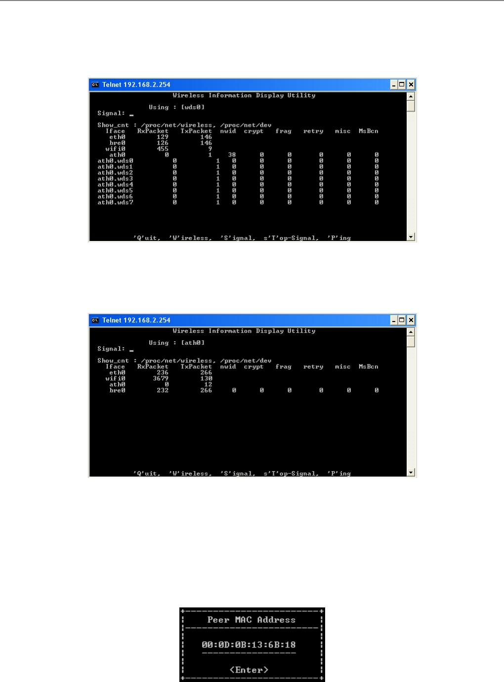
User Manual
TEW-455APBO 14dBi High Power Wireless Outdoor PoE Access Point
114
9 BRIDGE Mode : Enable all of BRIDGE link, the Choose Device window will be display wds0 to wds7.
Enter the desired device, the window will be display result.
9 CPE Mode : The Choose Device window only display ath0. Click Enter, the window will be display
result.
Î 'Q'uit : Type Q to close this utility.
Î 'W'ireless : Type W to open Choose Device window.
Î 'S'ignal : Type S to open Peer MAC Address window. Type the desired MAC address of associated peer
to display.
Click Enter to show signal strength of associated peer. The unit is RSSI.
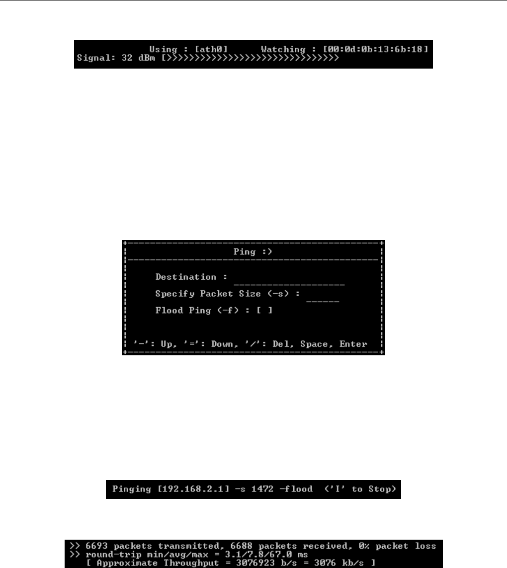
User Manual
TEW-455APBO 14dBi High Power Wireless Outdoor PoE Access Point
115
9 Using : The used device of system currently.
9 Watching : The MAC address of specified peer currently.
9 Signal : Indicate signal strength of specified peer currently.
Î S'T'op-Signal : Type T to stop display signal strength.
Î 'P'ing : Type P to open “Ping” window.
9 Destination : Enter the specify destination.
9 Specify Packet Size : Enter specify packet size.
9 Flood Ping : Click Space to enable or disable flood ping.
Click Enter to activated function. The processing of ping will be activated.
Click I to stop processing, and the statistic of ping will be display.
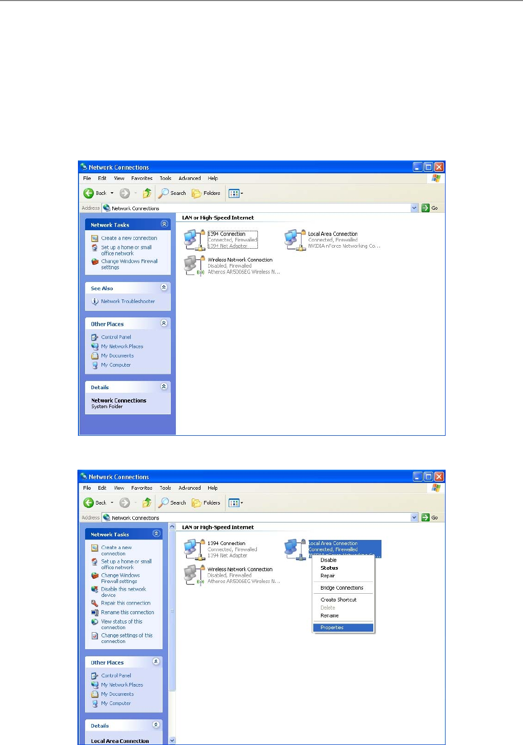
User Manual
TEW-455APBO 14dBi High Power Wireless Outdoor PoE Access Point
116
Appendix A. Windows TCP/IP Settings
Windows XP
1. Click Start -> Settings -> Control Panel, and then “Control Panel” window appears. Click on “Network
Connections”, and then “Network Connections” window appears.
2. Click right on “Local Area Connection”, and select Properties.
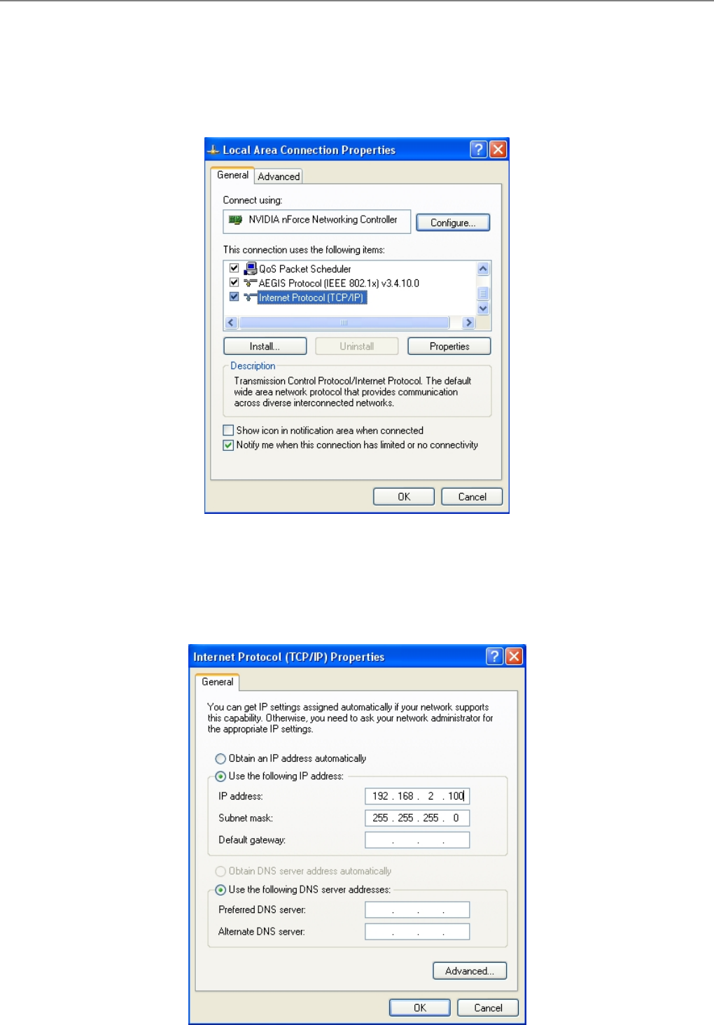
User Manual
TEW-455APBO 14dBi High Power Wireless Outdoor PoE Access Point
117
3. In “Local Area Connection Properties” window, select “Internet Protocol (TCP/IP)” and click on
Properties button.
4. Select “Use the following IP address”, and type in
IP address : 192.168.2.100
Subnet mask : 255.255.255.0

User Manual
TEW-455APBO 14dBi High Power Wireless Outdoor PoE Access Point
118
Appendix B. Valid Characters when using WMI
Table C Valid Characters for using WMI
Block Field Valid Characters
IP Address IP Format; 1-254
IP Netmask 128.0.0.0 ~ 255.255.255.252
IP Gateway IP Format; 1-254
Primary IP Format; 1-254
Secondary IP Format; 1-254
LAN
Hostname Length : 32
0-9, A-Z, a-z
@ - _ .
Manual MAC Address 12 HEX chars
IP Address IP Format; 1-254
IP Netmask 128.0.0.0 ~ 255.255.255.252
IP Gateway IP Format; 1-254
Hostname Length : 32
0-9, A-Z, a-z
@ - _ .
User name Length : 32
0-9, A-Z, a-z
~ ! @ # $ % ^ * ( ) _ + - { } | : < > ? [ ] / ; ` , . =
Password Length : 32
0-9, A-Z, a-z
~ ! @ # $ % ^ * ( ) _ + - { } | : < > ? [ ] / ; ` , . =
MTU 576 ~ 1492
Idle Time 0 ~ 60 minutes
Primary IP Format; 1-254
WAN
Secondary IP Format; 1-254
Start IP IP Format; 1-254
End IP IP Format; 1-254
DNS1 IP IP Format; 1-254
DNS2 IP IP Format; 1-254
WINS IP IP Format; 1-254
DHCP Server
Domain Length : 32
0-9, A-Z, a-z
~ ! @ # $ % ^ * ( ) _ + - { } | : < > ? [ ] / ; ` , . =

User Manual
TEW-455APBO 14dBi High Power Wireless Outdoor PoE Access Point
119
Table C Valid Characters for using WMI (continued)
Block Field Valid Characters
System Name Length : 32
0-9, A-Z, a-z
~ ! @ # $ % ^ * ( ) _ + - { } | : < > ? [ ] / ; ` , . =
Description Length : 32
0-9, A-Z, a-z
Space
~ ! @ # $ % ^ * ( ) _ + - { } | : < > ? [ ] / ; ` , . =
Location Length : 32
0-9, A-Z, a-z
~ ! @ # $ % ^ * ( ) _ + - { } | : < > ? [ ] / ; ` , . =
New Password Length : 4 ~ 30
0-9, A-Z, a-z
~ ! @ # $ % ^ * ( ) _ + - { } | : < > ? [ ] / ; ` , . =
Check New Password Length : 4 ~ 30
0-9, A-Z, a-z
~ ! @ # $ % ^ * ( ) _ + - { } | : < > ? [ ] / ; ` , . =
HTTP Port 1 ~ 65535
Management
Telnet Port 1 ~ 65535
RO community Length : 32
0-9, A-Z, a-z
~ ! @ # $ % ^ * ( ) _ + - { } | : < > ? [ ] ; ` , . =
RW community Length : 32
0-9, A-Z, a-z
~ ! @ # $ % ^ * ( ) _ + - { } | : < > ? [ ] ; ` , . =
RO user Length : 31
0-9, A-Z, a-z
~ ! @ # $ % ^ * ( ) _ + - { } | : < > ? [ ] ; ` , . =
RO password Length : 8 ~ 32
0-9, A-Z, a-z
~ ! @ # $ % ^ * ( ) _ + - { } | : < > ? [ ] ; ` , . =
RW user Length : 31
0-9, A-Z, a-z
~ ! @ # $ % ^ * ( ) _ + - { } | : < > ? [ ] ; ` , . =
RW password Length : 8 ~ 32
0-9, A-Z, a-z
~ ! @ # $ % ^ * ( ) _ + - { } | : < > ? [ ] ; ` , . =
Community Length : 32
0-9, A-Z, a-z
~ ! @ # $ % ^ * ( ) _ + - { } | : < > ? [ ] ; ` , . =
SNMP
IP IP Format; 1-254

User Manual
TEW-455APBO 14dBi High Power Wireless Outdoor PoE Access Point
120
Table C Valid Characters for using WMI (continued)
Block Field Valid Characters
ESSID Length : 31
0-9, A-Z, a-z
~ ! @ # $ % ^ * ( ) _ + - { } | : < > ? [ ] / ; ` , . =
WEP Key 10, 26, 32 HEX chars
General Setup
(CPE Mode)
Shared Key 1 ~ 63 ASCII chars; 64 HEX chars
Slot Time 1 ~ 1489
ACK Time 1 ~ 372
CTS Time 1 ~ 744
RSSI Threshold -128 ~ 127
Beacon Interval 10 ~ 5000
Date Beacon Rate 1 ~ 15
Fragment Threshold 256 ~ 2346
Advanced Setup
(BS&BRIDGE
Mode)
RTS Threshold 1 ~ 2346
Slot Time 1 ~ 1489
ACK Time 1 ~ 372
CTS Time 1 ~ 744
Fragment Threshold 256 ~ 2346
Advanced Setup
(CPE Mode)
RTS Threshold 1 ~ 2346
ESSID Length : 31
0-9, A-Z, a-z
~ ! @ # $ % ^ * ( ) _ + - { } | : < > ? [ ] / ; ` , . =
Maximum Clients 1 ~ 32
VLAN ID 1 ~ 4094 ; 0 is disable
Pass phrase 5, 13, 16 ASCII chars
WEP Key 10, 26, 32 HEX chars
Group Key Update 10 ~ 99999999 seconds
Master Key Update 10 ~ 99999999 seconds
Pre-Shared Key 8 ~ 63 ASCII chars; 64 HEX chars
Authentication Server IP Format; 1-254
Authentication Port 1 ~ 65535
Shared Secret 1 ~ 64 characters
EAP Reauth Period 300 ~ 99999999; default is 3600, 0 is disable
Accounting Server IP Format; 1-254
Accounting Port 1 ~ 65535
Virtual BS Setup
WEP Key Update 0 ~ 99999999 ; default is 300, 0 is disable

User Manual
TEW-455APBO 14dBi High Power Wireless Outdoor PoE Access Point
121
Table C Valid Characters for using WMI (continued)
Block Field Valid Characters
ESSID Length : 31
0-9, A-Z, a-z
~ ! @ # $ % ^ * ( ) _ + - { } | : < > ? [ ] / ; ` , . =
Peer's MAC Address 12 HEX chars
VLAN ID 1 ~ 4094 ; 0 is disable
Description Length : 32
0-9, A-Z, a-z
Space
~ ! @ # $ % ^ * ( ) _ + - { } | : < > ? [ ] / ; ` , . =
BRIDGE Setup
WEP Key 10, 26, 32 HEX chars
Source Address IP Format; 1-254
Source Mask 0 ~ 32
Source Port 1 ~ 65535
Destination Address IP Format; 1-254
Destination Mask 0 ~ 32
IP Rule Setup
Destination Port 1 ~ 65535
MAC Rule Setup MAC address MAC Format; 12 HEX chars
Description Length : 32
0-9, A-Z, a-z
space
~ ! @ # $ % ^ * ( ) _ + - { } | : < > ? [ ] / ; ` , . =
Private IP IP Formate; 1-254
Private Port 1 ~ 65535
Virtual Server
Public Port 1 ~ 65535
DMZ IP Address IP Format; 1-254
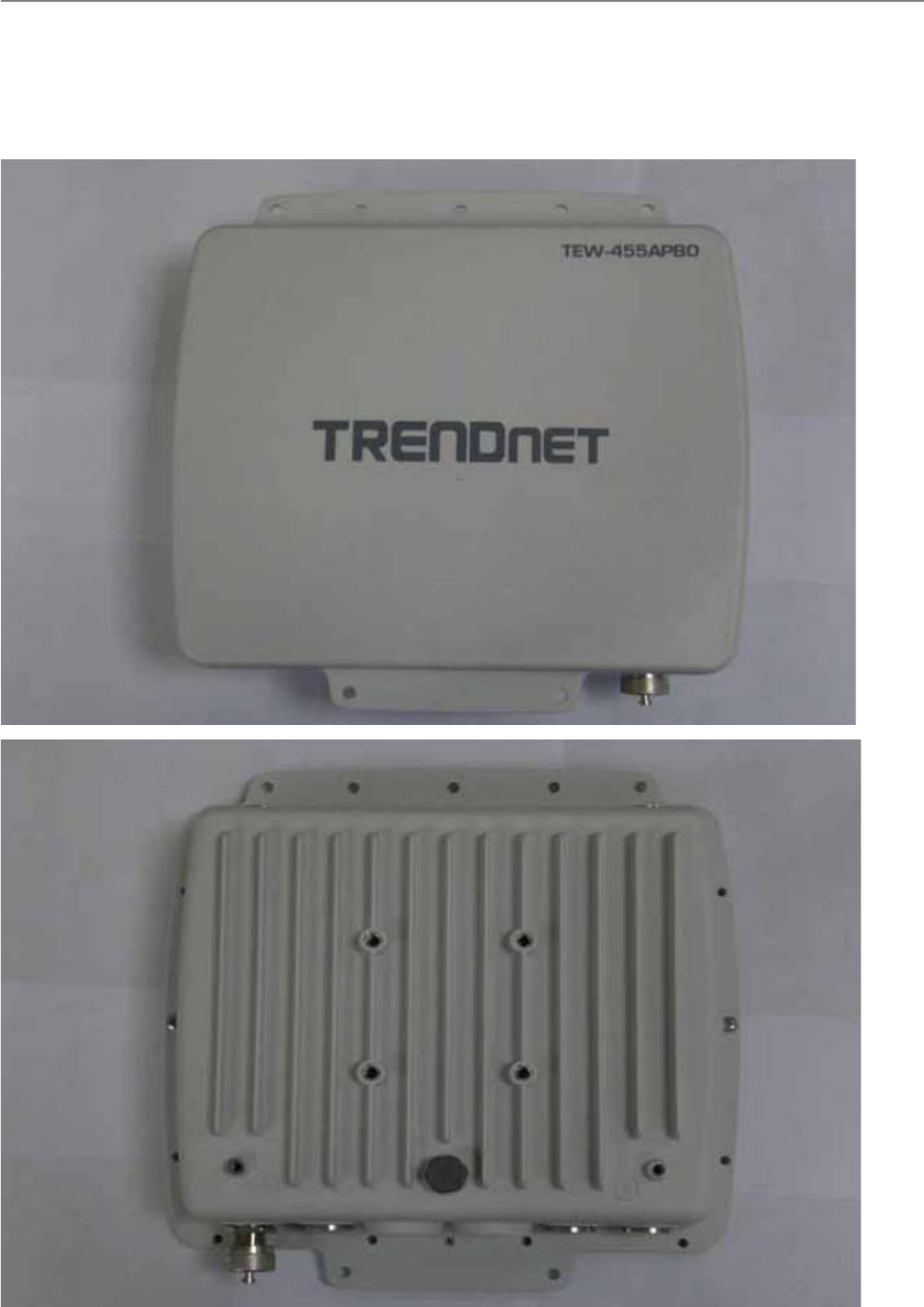
User Manual
TEW-455APBO 14dBi High Power Wireless Outdoor PoE Access Point
122
Appendix D. All Antenna type for Products
A. Internal Patch 1 Antenna (Antenna Gain : 12.84dBi)
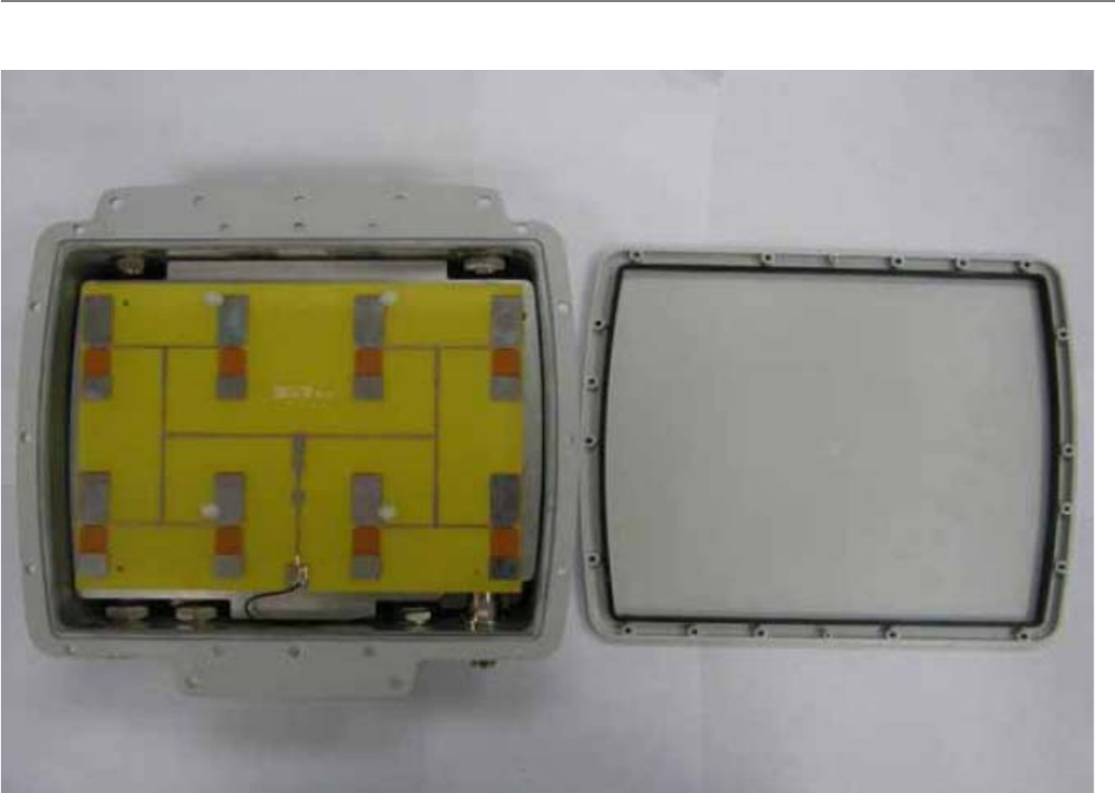
User Manual
TEW-455APBO 14dBi High Power Wireless Outdoor PoE Access Point
123

User Manual
TEW-455APBO 14dBi High Power Wireless Outdoor PoE Access Point
124
Federal Communications Commission (FCC) Statement
15.21
You are cautioned that changes or modifications not expressly approved by the part responsible
for compliance could void the user’s authority to operate the equipment.
15.105(b)
This equipment has been tested and found to comply with the limits for a Class B digital device,
pursuant to part 15 of the FCC rules. These limits are designed to provide reasonable protection
against harmful interference in a residential installation. This equipment generates, uses and
can radiate radio frequency energy and, if not installed and used in accordance with the
instructions, may cause harmful interference to radio communications. However, there is no
guarantee that interference will not occur in a particular installation. If this equipment does
cause harmful interference to radio or television reception, which can be determined by turning
the equipment off and on, the user is encouraged to try to correct the interference by one or
more of the following measures:
-Reorient or relocate the receiving antenna.
-Increase the separation between the equipment and receiver.
-Connect the equipment into an outlet on a circuit different from that to which the receiver is
connected.
-Consult the dealer or an experienced radio/TV technician for help.
This device complies with Part 15 of the FCC Rules.Operation is subject to the following
two conditions:
1) this device may not cause harmful interference and
2) this device must accept any interference received, including interference that may cause
undesired operation of the device.
FCC RF Radiation Exposure Statement:
This equipment complies with FCC radiation exposure limits set forth for an uncontrolled
environment. End users must follow the specific operating instructions for satisfying RF
exposure compliance. This transmitter must not be co-located or operating in conjunction with
any other antenna or transmitter. The minimum separation distance between antenna and
people is 30 cm.