TRIMBLE EUROPE 110610 GSM/GPRS/UMTS/HSPA Module User Manual SP90MUG
TRIMBLE EUROPE BV GSM/GPRS/UMTS/HSPA Module SP90MUG
Contents
- 1. Host user manual 1_SP90M_UG_B_Draft2_en-v1a.pdf
- 2. Host user manual 1_SP90M_UG_B_Draft2_en-v1b.pdf
- 3. Host user manual 2_SP90M_UG_B_Draft2_en-v2.pdf
- 4. User guide_SP85_UG_A_en-part2_Part1
- 5. User guide_SP85_UG_A_en-part2_Part2
- 6. User guide_SP85_UG_A_en-part2_Part3
- 7. User guide_SP85_UG_A_en-part2_Part4
Host user manual 1_SP90M_UG_B_Draft2_en-v1a.pdf
User Guide
SP90m GNSS Receiver
Rev B, Sep 11, 2017,
Preliminary

Legal Notices
©2017 Trimble Inc. All rights reserved.
All product and brand names mentioned in this
publication are trademarks of their respective hold-
ers.
SP90m User Guide, Rev. B, September 2017.
Limited Warranty Terms and Conditions
Product Limited Warranty. Subject to the terms and
conditions set forth herein, Trimble Inc. (“Trimble”)
warrants that for a period of 2 years from date of
purchase this Spectra Precision product (the
“Product”) will substantially conform to our public-
ly available specifications for the Product and that
the hardware and any storage media components of
the Product will be substantially free from defects
in materials and workmanship.
Product Software. Product software, whether built
into hardware circuitry as firmware, provided as a
standalone computer software product, embedded
in flash memory, or stored on magnetic or other me-
dia, is licensed solely for use with or as an integral
part of the Product and is not sold. The terms of the
end user license agreement govern the use of the
Product Software, including any differing limited
warranty terms, exclusions and limitations, which
shall control over the terms and conditions set forth
in the limited Product warranty.
Warranty Remedies. If the Product fails during the
warranty period for reasons covered by this limited
warranty and you notify us of such failure during
the warranty period, we will repair OR replace the
nonconforming Product with new, equivalent to
new, or reconditioned parts or Product, OR refund
the Product purchase price paid by you, at our op-
tion, upon your return of the Product in accordance
with our product return procedures then in effect.
Warning to Users in the United States
Federal Communication Commission Interference
Statement 47 CFR Section 15, 105(b). This equip-
ment has been tested and found to comply with the
limits for a Class B digital device, pursuant to Part
15 of the FCC Rules. These limits are designed to
provide reasonable protection against harmful in-
terference in a residential installation. This equip-
ment generates, uses and can radiate radio
frequency energy and, if not installed and used in
accordance with the instructions, may cause harm-
ful interference to radio communication. However,
there is no guarantee that interference will not oc-
cur in a particular installation. If this equipment
does cause harmful interference to radio or televi-
sion reception, which can be determined by turning
the equipment off and on, the user is encouraged
to try to correct the interference by one or more of
the following measures:
• Reorient or relocate the receiving antenna.
• Increase the separation between the equip-
ment and the receiver.
• Connect the equipment into an outlet on a cir-
cuit different from that to which the receiver is
connected.
• Consult the dealer or an experienced radio/TV
technician for help.
The SP90m complies with Part 15 of the FCC
Rules. Operation is subject to the
following two conditions: (1) This device may not
cause harmful interference, and (2) this device
must accept any interference received, including
interference that may cause undesired operation.
No Unauthorized Modifications
47 CFR Section 15.21
CAUTION: This equipment may not be modified,
altered, or changed in any way without signed writ-
ten permission from Trimble Inc.. Unauthorized
modification may void the equipment authorization
from the FCC and will void the Trimble warranty.
This device complies with FCC RF radiation expo-
sure limits set forth for general population (uncon-
trolled exposure). This device must be installed to
provide a separation distance of at least 30 cm
from all persons and must not be collocated or op-
erating in conjunction with any other antenna or
transmitter.
Warning to the Users in the Canada
This device complies with Industry Canada RF radi-
ation exposure limits set forth for general popula-
tion (uncontrolled exposure). This device must be
installed to provide a separation distance of at least
30 cm from all persons and must not be collocated
or operating in conjunction with any other antenna
or transmitter.
This device complies with Industry Canada licence-
exempt RSS standard(s). Operation is subject to
the following two conditions: (1) this device may
not cause interference, and (2) this device must ac-
cept any interference, including interference that
may cause undesired operation of the device.
Attention pour les utilisateurs au Canada
Le présent appareil est conforme aux niveaux li-
mites d’exigences d’exposition RF aux personnes
définies par Industrie Canada. Cet appareil doit
être installé afin d’offrir une distance de séparation
d’au moins 30 cm avec l’utilisateur, et ne doit pas
être installé à proximité ou être utilisé en conjonc-
tion avec une autre antenne ou un autre émetteur.
Le présent appareil est conforme aux CNR d’Indus-
trie Canada applicables aux appareils radio
exempts de licence. L’exploitation est autorisée aux
deux conditions suivantes: (1) il ne doit pas pro-
duire de brouillage, et (2) l’utilisateur du dispositif
doit être prêt a accepter tout brouillage radioélec-
trique reçu, même si ce brouillage est susceptible
de compromettre le fonctionnement du dispositif.
Europe
This product has been tested and found to comply
with the requirements for a Class B device pursuant
to European Council Directive 89/336/EEC on
EMC, thereby satisfying the requirements for CE
Marking and sales within the European Economic
Area (EEA). These requirements are designed to
provide reasonable protection against harmful in-
terference when the equipment is operated in a res-
idential or commercial environment.
Notice to Our European Union Customers
For product recycling instructions and more infor-
mation, please go to http://www.spectrapreci-
sion.com/eng/weee-and-rohs.
Recycling in Europe: To recycle Spectra Precision
WEEE (Waste Electrical and Electronic Equipment
products that run on electric power), call +31 497
53 24 30 and ask for the “WEEE Associate”. Or,
mail a request for recycling instructions to:
Trimble Europe BV
c/o Menlo Worldwide Logistics
Meerheide 45
5521 DZ Eersel, NL
Declaration of Conformity
We, Spectra Precision,
declare under sole responsibility that the product:
SP90m GNSS receiver
complies with Part 15 of FCC Rules.
Operation is subject to the following two condi-
tions:
(1) this device may not cause harmful interference,
(2) and this device must accept any interference
received, including interference that may cause
undesired operation.
Explanations on logos and acronyms found on the
receiver sticker:
:
Federal Communication Commission
:
Restriction of Hazardous Substances Directive
:
Conformité européenne (European Compliance)
:
Waste Electrical and Electronic Equipment Directive
IC: Industry Canada
V:
Volts
: Direct Current
Rechargeable Lithium-ion Batteries
This receiver uses one rechargeable Lithium-ion
battery.
WARNING - Do not damage the rechargeable Lithi-
um-ion batteries. A damaged battery can cause an
explosion or fire, and can result in personal injury
and/or property damage. To prevent injury or dam-
age:
• Do not use or charge the batteries if they ap-
pear to be damaged. Signs of damage include,
but are not limited to, discoloration, warping,
and leaking battery fluid.
• Do not expose the batteries to fire, high tem-
perature, or direct sunlight.
• Do not immerse the batteries in water.
• Do not use or store the batteries inside a vehi-
cle during hot weather.
• Do not drop or puncture the batteries.
• Do not open the batteries or short-circuit their
contacts.
WARNING - Avoid contact with a rechargeable Lith-
ium-ion battery if it appears to be leaking. Battery
fluid is corrosive, and contact with it can result in
personal injury and/or property damage. To prevent
injury or damage:
• If a battery leaks, avoid contact with the bat-
tery fluid.
• If battery fluid gets into your eyes, immediate-
ly rinse your eyes with clean water and seek
medical attention. Do not rub your eyes!
• If battery fluid gets onto your skin or clothing,
immediately use clean water to wash off the
battery fluid.
WARNING - Charge and use the rechargeable Lith-
ium-ion batteries only in strict accordance with the
instructions. Charging or using the batteries in un-
authorized equipment can cause an explosion or
fire, and can result in personal injury or/and equip-
ment damage. To prevent injury or damage:
• Do not charge a battery if it appears to be dam-
aged or leaking.
• USE EXCLUSIVELY the dual-battery charger
(P/N 53018010-SPN) or the AC/DC power
supply (P/N 107000) to charge the SP90m
Lithium-ion battery. See instructions in this
guide. These two devices are part of the
SP90m standard accessories list.
CHARGE THE BATTERIES ONLY IN THE
TEMPERATURE RANGE 0° to +40°C (32° to
104°F), at a maximum altitude of 2,000 me-
ters (6,562 feet).
• Discontinue charging a battery that gives off
extreme heat or a burning odor.
• Use the batteries only in Spectra Precision
equipment that is specified to use them.
• Use the batteries only for their intended use
and according to the instructions in the prod-
uct documentation.
Disposing of the Rechargeable Lithium-ion Battery
Discharge the Lithium-ion battery before disposing
of it. When disposing of the battery, be sure to do
so in an environmentally sensitive manner. Adhere
to any local and national regulations concerning
battery disposal or recycling.
CAUTION - RISK OF EXPLOSION IF BATTERY IS
REPLACED BY AN INCORRECT TYPE.
DISPOSE OF USED BATTERIES ACCORDING TO
THE INSTRUCTIONS”
ATTENTION - RISQUE D'EXPLOSION SI LA BAT-
TERIE EST REMPLACÉE PAR UNE BATTERIE DE
TYPE INCORRECT.
METTRE AU REBUT LES BATTERIES USAGÉES
CONFORMÉMENT AUX INSTRUCTIONS.
Receiver Use and Care
The receiver can withstand the rough treatment
that typically occurs in the field. However, the re-
ceiver is a high-precision electronic instrument and
should be treated with reasonable care.
CAUTION - Operating or storing the receiver out-
side the specified temperature range can damage
it. For more information, see Physical Specifica-
tions in this guide.
High-power signals from a nearby radio or radar
transmitter can overwhelm the receiver circuits.
This does not harm the instrument, but it can pre-
vent the receiver from functioning correctly. Do not
use the receiver within 400 meters (1312 feet) of
powerful radar, television or other transmitters.
Low-power transmitters such as those used in cell
phones and two-way radios do not normally inter-
fere with receiver operations.

For more information, contact your Spectra Precision
distributor.
Bluetooth & Wifi Radios
The radiated output power of the wireless radios is far
below the FCC radio-frequency exposure limits. Nev-
ertheless, the wireless radios shall be used in such a
manner that the Spectra Precision receiver is 30 cm
(11.8”) or further from the human body.
The internal wireless radios operate within guidelines
found in radio-frequency safety standards and rec-
ommendations, which reflect the consensus of the
scientific community. Spectra precision therefore be-
lieves the internal wireless radios are safe for use by
consumers.
The level of energy emitted is far less than the elec-
tromagnetic energy emitted by wireless devices such
as mobile phones. However, the use of wireless radi-
os may be restricted in some situations or environ-
ments, such as on aircraft. If you are unsure of
restrictions, you are encouraged to ask for authoriza-
tion before turning on the wireless radios.
COCOM Limits
The US Department of Commerce requires that all
exportable GNSS products contain performance lim-
itations so that they cannot be used in a manner that
could threaten the security of the United States.
The following limitation is implemented on the re-
ceiver: Immediate access to satellite measurements
and navigation results is disabled when the receiver’s
velocity is computed to be greater than 1000 knots,
or its altitude is computed to be above 17,000 me-
ters (59,055 feet). The receiver continuously resets
until the COCOM situation is cleared.
Technical Assistance
If you have a problem and cannot find the informa-
tion you need in the product documentation, contact
your local distributor. Alternatively, request technical
support using the Spectra Precision website at
www.spectraprecision.com.
Your Comments
Your feedback about the supporting documentation
helps us improve it with each revision. Email your
comments to documentation_feedback@spectrapre-
cision.com.
UHF Radios
Regulations and Safety. The receiver may be fitted
with an internal radio as an option. It can also be
connected to an external UHF radio.
Regulations regarding the use of Ultra High Frequen-
cy (UHF) radio-modems vary greatly from country to
country. In some countries, the UHF kit may be used
without obtaining an end-user license. Other coun-
tries require end-user licensing. For licensing infor-
mation, consult your local Spectra Precision dealer.
Before operating the receiver with the UHF kit, deter-
mine if authorization or a license to operate the UHF
kit is required in your country. It is the end-user’s re-
sponsibility to obtain an operator’s permit or license
for the location or country of use.
Exposure to RF energy is an important safety consid-
eration. The FCC has adopted a safety standard for
human exposure to radio-frequency electromagnetic
energy.
Proper use of this radio modem results in exposure
below government limits. The following precautions
are recommended:
• DO NOT operate the transmitter when someone
is within 30 cm (11.8 inches) of the antenna.
• DO NOT collocate (place within 30 cm) the ra-
dio antenna with any other transmitting device.
• DO NOT operate the transmitter unless all RF
connectors are secure and any open connectors
are properly terminated.
• DO NOT operate the equipment near electric
blasting caps or in an explosive atmosphere.
• All equipment must be properly grounded ac-
cording to Spectra Precision installation in-
structions for safe operation.
• All equipment should be serviced only by a qual-
ified technician.
Connecting the SP90m to an external battery using
an SAE-terminated cable
The wires used should all be certified UL 758 and
CSA C22.2 No. 210, or similar. Minimum wire sec-
tion should be AWG 18, with insertion of a 5-A fuse
in series. The fuse should be certified “UL listed”
and CSA certified 3-30 A (or equivalent).
Table of Contents
Introduction to SP90m.........................................................................1
First Steps ..........................................................................................2
Unpacking ............................................................................2
Basic Setup ..........................................................................2
Default Configuration.............................................................2
Customizing Receiver Operation..............................................3
System Components Overview.............................................................4
SP90m Packout Kits..............................................................4
Standard Accessories .........................................................4
Country-Specific Power Cord...................................................6
GNSS Antenna and Antenna Cables ........................................7
Pre-Installed Firmware Options ...............................................7
Upgradable Firmware Options.................................................8
Other Optional Accessories .....................................................8
Equipment Description.........................................................................9
Front Panel...........................................................................9
Rear Panel..........................................................................11
SIM Card ............................................................................13
Battery Model & Battery Compartment...................................13
Buzzer................................................................................14
Port Pinouts........................................................................14
USB Port.........................................................................14
Power In, Serial Port A .....................................................15
Serial Port B....................................................................15
Serial Port F ....................................................................16
Ethernet Port...................................................................17
Physical and Virtual Port IDs.................................................17
Installation Instructions....................................................................18
Receiver .............................................................................18
Tripod Mount...................................................................18
Bottom Plane Mount ........................................................18
Bumper Mount.................................................................19
GNSS Antennas Setup for Heading Measurements..................19
Choosing the Appropriate Baseline Length..........................19
Elevation Offset ...............................................................20
Azimuth Offset.................................................................21
Azimuth Offset, Antenna Setup & Resulting Heading...........22
Delivering an RTK Position for the Primary Antenna.............22
Powering the SP90m.........................................................................23
External DC Source vs. Internal Battery..................................23
Power Mode ........................................................................23
Charging the Internal Battery ................................................24
Using an External Battery .....................................................25
Receiver User Interface .................................................................... 26
Welcome Screen..................................................................26
Using the Front Panel Controls..............................................26
General Status ....................................................................28
Radio .................................................................................32
GSM...................................................................................34
WiFi ...................................................................................35
Ethernet .............................................................................36
Display Settings...................................................................36
Advanced Settings ...............................................................37
Base Mode..........................................................................39
Raw Data Recording.............................................................42
Power-Off Screen.................................................................43
Using a USB Key............................................................................... 44
To Copy Files ......................................................................44
To Upgrade the Firmware .....................................................44
Getting Started With the Web Server.................................................. 46
Introduction to the Web Server..............................................46
Description and Function ..................................................46
Running the Web Server for the First Time..........................46
Security ..........................................................................46
WiFi-Based TCP/IP Connection..............................................47
Setting Up the WiFi Device ...............................................47
Using the WiFi Device as Access Point ...............................49
Using the WiFi Device as Client .........................................49
Using the WiFi Device as both Access Point and Client ........50
Ethernet-Based TCP/IP Connection........................................50
Setting Up the Ethernet Device .........................................51
TCP/IP Connection Within a Local Network .........................52
TCP/IP Connection Through the Public Internet...................53
Introduction to Multi-Operating Mode ....................................54
Using SP90m With a Single Antenna ................................................. 55
Specifying the Model of Antenna Used ..................................55
Raw Data Recording ............................................................56
Using the Web Server .......................................................56
Working from the Receiver Front Panel...............................56
Autonomous or SDGPS (SBAS) Rover ....................................57
RTK or DGPS Rover .............................................................58
Hot Standby RTK Rover........................................................59
Trimble RTX Rover...............................................................60
RTK + Relative RTK Rover....................................................62
Hot Standby RTK+ Relative RTK ...........................................64
Relative RTK Rover..............................................................66
Static or Moving Base ..........................................................67
Using the Web Server .......................................................67
Working from the Receiver Front Panel...............................68
Using SP90m With Two Antennas ...................................................... 69
Specifying the Models of Antennas Used................................69
SP90m Delivering Heading Measurements.............................70
Dual-RTK Rover...................................................................71
Dual-Relative RTK ...............................................................73
Programming Data Outputs.................................................................75
Rover Output Messages........................................................75
Base Data Messages ............................................................76
Raw Data Recording.............................................................77
Available NMEA Messages....................................................78
Appendices.......................................................................................79
Specifications .....................................................................79
GNSS Engine...................................................................79
Features..........................................................................79
GNSS Sensor Performance................................................80
Precise Positioning Performance........................................81
Real-Time Performance ....................................................82
Post-Processing Accuracy (RMS) .......................................82
Data Logging Characteristics .............................................82
Memory...........................................................................82
Embedded Web Server......................................................82
User and I/O Interface ......................................................83
Physical and Electrical Characteristics ...............................83
Environmental Characteristics ...........................................84
1PPS Output.......................................................................86
Event Marker Input ..............................................................87
Resetting the Receiver .........................................................87
Upgrading the Receiver Firmware..........................................88
SP Loader Software Utility....................................................88
Installing SP Loader .........................................................88
Getting Started With SP Loader .........................................88
Upgrading Receiver Firmware............................................89
Installing a Firmware Option .............................................90
Activating a CenterPoint RTX Subscription..........................91
Reading Receiver Warranty Expiration Date.........................91
SP File Manager Software Utility ..........................................92
Installing SP File Manager ................................................92
Connecting SP90m to your Computer.................................92
Getting Started With SP File Manager ................................92
Establishing a Connection with the Receiver .......................94
Copying Files to the Office Computer .................................94
Deleting Files from the Receiver ........................................94
UHF Networking..................................................................95
NMEA Messages..................................................................96
ALR: Alarms ....................................................................96
ARA: True Heading...........................................................96
ARR: Vector & Accuracy....................................................97
ATT: True Heading ...........................................................98
AVR: Time, Yaw, Tilt ........................................................98
BTS: Bluetooth Status ......................................................99
CAP: Received Base Antenna ............................................99
CPA: Received Antenna Height........................................100
CPO: Received Base Position ..........................................100
DDM: Differential Decoder Message.................................100
DDS: Differential Decoder Status.....................................101
DTM: Datum Reference ..................................................102
GBS: GNSS Satellite Fault Detection ...............................102
GGA: GNSS Position Message .........................................103
GGK: GNSS Position Message .........................................103
GGKX: GNSS Position Message .......................................104
GLL: Geographic Position - Latitude/Longitude..................105
GMP: GNSS Map Projection Fix Data ...............................106
GNS: GNSS Fix Data ......................................................107
GRS: GNSS Range Residuals ..........................................108
GSA: GNSS DOP and Active Satellites..............................108
GST: GNSS Pseudo-range Error Statistics .........................109
GSV: GNSS Satellites in View..........................................109
HDT: True Heading.........................................................110
HPR: True Heading ........................................................110
LTN: Latency.................................................................111
MDM: Modem State and Parameter..................................111
POS: Position ................................................................112
PTT: PPS Time Tag ........................................................113
PWR: Power Status.........................................................113
RCS: Recording Status ...................................................114
RMC: Recommended Minimum Specific GNSS Data .........115
SBD: BEIDOU Satellites Status .......................................115
SGA: GALILEO Satellites Status (E1,E5a,E5b)..................116
SGL: GLONASS Satellites Status .....................................116
SGO: GALILEO Satellites Status (E1,E5a,E5b,E6).............116
SGP: GPS Satellites Status .............................................117
SIR: IRNSS Satellites Status...........................................117
SLB: L-Band Satellites Status .........................................117
SQZ: QZSS Satellites Status............................................118
SSB: SBAS Satellites Status ...........................................118
TEM: Receiver Temperature ............................................118
THS: True Heading and Status ........................................119
TTT: Event Marker..........................................................119
VCR: Vector and Accuracy...............................................120
VCT: Vector and Accuracy ...............................................121
VEL: Velocity .................................................................122
VTG: Course Over Ground and Ground Speed ....................122
ZDA: Date & Time ..........................................................122
1
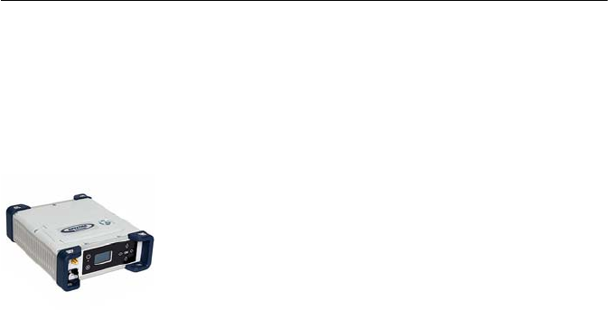
Introduction to SP90m
The Spectra Precision SP90m is a powerful, highly versatile,
ultra-rugged, and reliable GNSS positioning solution for a
wide variety of real-time and post-processing applications. It
also comes with a variety of integrated communications
options, such as Bluetooth, WiFi, UHF radio, cellular modem,
and two MSS L-band channels to receive Trimble RTX
correction services.
The modular design of the SP90m allows for maximum
flexibility on how the receiver can be used, such as base
station, continuously operating reference station (CORS),
RTK/RTX rover, for on-board machine integration, vessels,
etc. The ultra-rugged design of the aluminum receiver
housing protects the investment, especially in tough field
environments.
The state-of-the-art and patented Z-Blade GNSS-centric
technology uses all available GNSS signals to deliver fast and
reliable real-time positions. Besides supporting all currently
available and future planned GNSS satellite signals, the
SP90m GNSS receiver allows the connection of two GNSS
antennas for precise heading determination without the need
for a secondary GNSS receiver.
2
First Steps
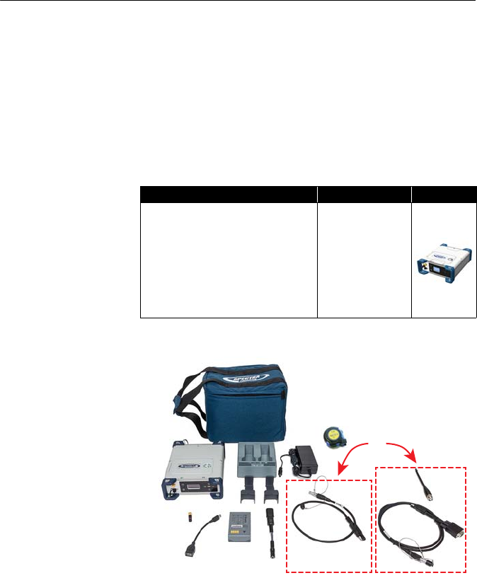
Unpacking In its basic version, the SP90m is delivered with a transport
bag, a Li-Ion battery, a dual-battery charger with battery
inserts, an AC/DC power supply, a Bluetooth/WiFi antenna
and accessories (see details in System Components Overview
on page 4).
Additionally, a choice of GNSS antenna and coaxial cable
should have been made, as well as that of a country-specific
power cord.
When the chosen model of SP90m includes an internal radio,
the power cable is different and a UHF antenna is added to
the supply (see details on page 4).
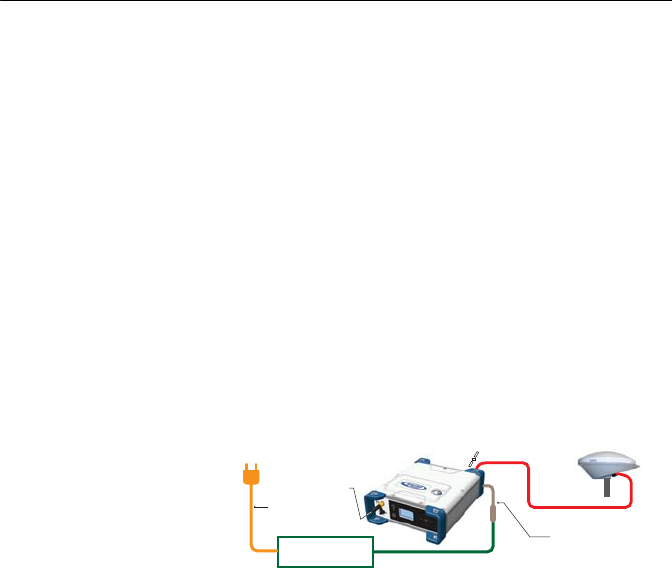
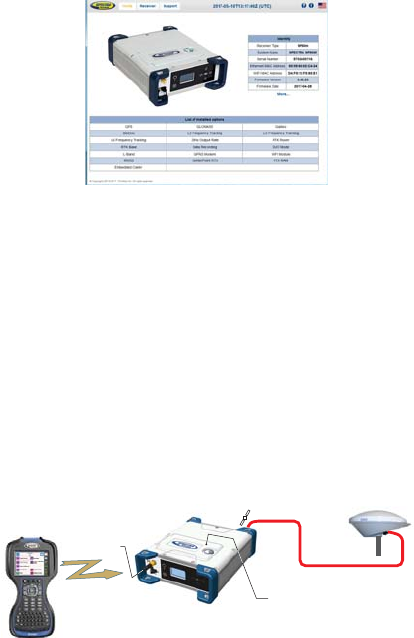
Basic Setup You may have the Li-Ion battery charged separately on the
dual-battery charger (see page 24) or it can be placed in the
receiver (see page 13) to be charged by the external DC
source (AC/DC power supply) when connected as indicated
below.
Default
Configuration
The SP90m is shipped from the factory in the following
configuration:
• Antenna configuration: Single antenna (GNSS input #1)
• Selected GNSS constellations and signals: All
• Elevation mask (for position and raw data): 5 degrees
• Anti-theft and startup protection: Both OFF
• Base Mode: OFF (the receiver will operate as a rover)
• Receiver with internal radio: Radio is ON
• GSM, WiFi: Both devices OFF
• Bluetooth, Ethernet: Both devices ON
• Raw data recording: OFF
• Internal GSM antenna is used
• Preset messages for raw data recording: ATOM (PVT, ATR,
NAV, DAT, RNX-0, OCC)
• Distance unit used: Meters
•
No corrections messages preset to be generated in base mode
1
AC/DC Power Supply
Power Line
SAE-to-DC Adapter
Coaxial cable
GNSS Antenna
Power Cord
Bluetooth/WiFi
Antenna
3
• Screen orientation: Normal
• Screen timeout: 10 minutes
•Buzzer: ON
• Automatic receiver power-on and power-off: Disabled
• ATL Recording: OFF
• Access to Web Server: Protected. The default login is
"admin" and the default password is "password". These
may be changed using the Security tab in the Web Server.
Customizing
Receiver Operation
• If you wish to change the configuration, you need to:
– Run the Web Server: see Getting Started With the Web
Server on page 46.
– Then choose your operating mode and follow the
instructions to make it operational: See Using SP90m
With a Single Antenna on page 55 or Using SP90m
With Two Antennas on page 69.
NOTE: Web Server functions not described in this
manual are covered in the on-line context-sensitive help.
• In all those applications where the Spectra Precision
Survey Pro field software will be used, the configuration
steps needed before operating the receiver in the
requested mode may be taken directly from within Survey
Pro. Typically in this case, a Bluetooth connection will be
used between the data controller running Survey Pro and
the SP90m.
NOTE: Some configuration changes can also be made directly
from the receiver’s front panel. See Receiver User Interface
on page 26.
1
Coaxial cable
GNSS Antenna
Bluetooth/WiFi
Antenna
Powered from Internal Battery
Data Controller
running
Survey Pro
Bluetooth
4
System Components Overview
This section provides an overview of the different key items
composing the SP90m.
Depending on your purchase and based on the type of survey
you wish to perform, you may only have some of the listed
items. Please refer to the packing list for an accurate
description of the equipment that has been delivered to you.
NOTICE: Spectra Precision reserves the right to make
changes to the items listed below without prior notice.
SP90m
Packout Kits
Standard Accessories
The receiver you ordered was shipped with the following
standard accessories. (If needed, each of these items may be
Item Part Number Picture
SP90m, Survey, including standard
accessories (see next table):
• Worldwide use, without UHF radio
• Worldwide use, with UHF radio
• China only, without UHF radio
• China only, with UHF radio
• Latin America only, without UHF radio
• Latin America only, with UHF radio
• SP90M-101-00
• SP90M-101-60
• SP90M-101-00-20
• SP90M-101-60-20
• SP90M-101-00-50
• SP90M-101-60-50
Or
5
ordered separately as spare parts; Use the part numbers
mentioned in the table below when ordering.)
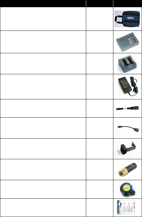
Item Part Number Picture
Spectra Precision Transport Bag 206490-ASH
Li-Ion battery,7.4 V DC, 3700 mAh 76767
Dual Battery Charger (does not include AC/DC
power supply and cable)
53018010-
SPN
AC/DC Power Supply, 65 W,19 V, 3.43 A, 100-
240 V AC, Class VI (used either to power the
receiver or the battery charger) (power cord not
provided; see section below)
107000
SAE-to-DC adapter cable, 0.15 m 88769-00
OTG Cable, USB A to Mini USB B 107535
Battery inserts for Dual Battery Charger (used
for mechanical adaptation of the battery to the
charger) (Qty: 2)
83664-00
Helical SMA 2.4 Bluetooth/WiFi antenna, RH
series 111403
Tape measure, 3.60 m (12 feet) 93374
Quick Start Guide -
6
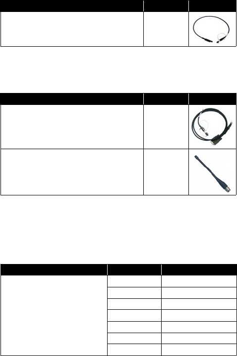
For part numbers not including a UHF radio (SP90M-101-
00, SP90M-101-00-20 and SP90M-101-00-50), the
following item is added to the standard accessories.
For part numbers including a UHF radio (SP90M-101-60,
SP90M-101-60-20 and SP90M-101-60-50), the following
items are added to the standard accessories.
Country-Specific
Power Cord
You should have ordered the power cord you need to power
the AC/DC power supply, depending on the country where the
receiver is to be used. The table below summarizes the
different part numbers available for this item.
Item Part Number Picture
7P Lemo-to-SAE power cable, 0.6 m 95715
Item Part Number Picture
Power/Data cable, 1.5 m, DB9-f to OS/7P/M
to power jack 59044
5” whip antenna (TNC) for 410-470 MHz radio 44085-60
Item Part Number Country/Continent
Power cord, 1.8 m (6 ft) in length
105778-SPN North America
78656-SPN Japan
78653-SPN Europe
78654-SPN UK
101202-SPN Taiwan
102376-SPN China
78655-SPN Australia

7
GNSS Antenna and
Antenna Cables
The Spectra Precision offer in terms of GNSS antennas and
coaxial cables that may be used with the SP90m is
summarized in the table below.
Pre-Installed
Firmware Options
The list of pre-installed firmware options is given below. It
applies to all available SP90m packout kits listed on page 4.
Item Part Number Picture
“Spectra Precision SPGA Rover”
antenna (can be used either as a rover
or base antenna)
135000-00
Coaxial, TNC/TNC, right angle, 1.6 m 58957-02-SPN
Coaxial, TNC/TNC, right angle, 10 m 58957-10-SPN
ID Designation
N GPS-SBAS-QZSS
G GLONASS
O GALILEO
B BEIDOU
HIRNSS
X L1TRACKING
Y L2TRACKING
Q L5TRACKING
T L6TRACKING
L LBAND
W 20Hz
JRTKROVER
K RTKBASE
D DUO
MMODEM
UWIFI
RRECORD

8
Upgradable
Firmware Options
These firmware options can be purchased separately to
upgrade the receiver.
NOTE: The result of a separate purchase is a POPN (Proof Of
Purchase Number) emailed to the buyer. The POPN is then
entered in the receiver using the SP Loader software utility
(see page 88) to activate the purchased firmware option.
Other Optional
Accessories
Other accessory kits (cables, antennas, radios) may be used
with the SP90m. Please contact your distributor for more
information.
ID Designation Part Number
8 Fast Output (50 Hz) 113329-01
c Embedded NTRIP Caster 113329-02
@1 Worldwide use (disables pre-installed Geofencing) 113329-03
In order to use the Trimble RTX service Center-
Point RTX, a subscription is required..
The result of the purchase will be a code that you
will have to type in, in the same way as you would
do to activate a firmware option in the receiver
using the Web Server.
Visit Trimble RTX
website to purchase
a subscription.
9
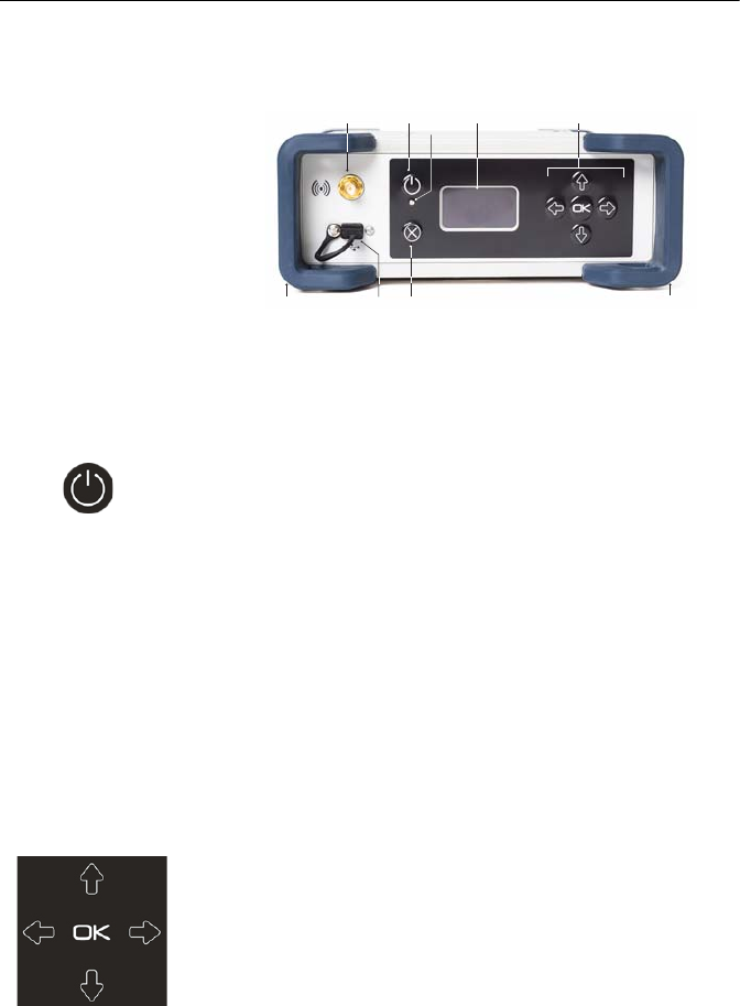
Equipment Description
Front Panel
•[1]: External Bluetooth/WiFi antenna connector. A coaxial
female connector (reverse SMA type) allowing you to
connect a Bluetooth or WiFi antenna for wireless
communication with a field terminal or any other device.
•[2]: Power button.
To turn on the receiver, press the Power button for about
two seconds until the power LED [5] turns solid green,
then release the button. The receiver will automatically
complete its initialization phase before it starts operating
normally.
To turn off the receiver, press the same Power button for
about two seconds. The Power LED will blink green until
the receiver gets turned off.
•[3]: Display screen. The display consists of a 128 x 64-
pixel, 1.5-inch monochrome blue-gray OLED screen.
Used in conjunction with the direction keys, the OK and
Escape keys, the display screen allows you to view and
edit different pages of information. See Receiver User
Interface on page 26 for a detailed description of the
information available from this screen.
After a few seconds of keypad inactivity, screen luminosity
is turned off.
•[4]: Keypad including four direction keys and a central OK
key. See details on page 26.
[1]
[6] [7] [8][8]
[2] [5] [3] [4]

10
•[5]: Power LED. Possible states:
•[6]: USB OTG mini connector (port U or M).
This is a five-contact connector. Depending on how it is
configured, the USB port can be connected to:
1. A USB host, such as a USB key (mass storage device),
using cable P/N 107535.
2. A USB device (port U), allowing USB serial
communication using a standard USB cable (not
provided).
This port is used typically for downloading/deleting files
using SP File Manager, (in this case the receiver is seen
as a disk) or upgrading firmware/warranty date using SP
Loader.
The first time you connect the SP90m to a computer
through a USB connection, the required driver will
automatically be installed on the computer. If however the
installed driver does not work, you may replace it with one
of the two drivers posted on the Spectra Precision website:
State Meaning
Off
SP90m is off and no external power source is
connected to the DC power input (but the inter-
nal battery may be present).
Solid green
SP90m is on (initializing or steady state),
being powered from an external power source.
If the internal battery is present, battery
charging from the external source will take
place if needed (see battery icon on General
Status screen).
Solid green, but
with 0.5-s “off” time
every 2 sec
SP90m is on (initializing or steady state),
being powered from the internal battery. No
external power source is applied.
Blinking green
SP90m is running a 5-second power-off
sequence following a long press on the Power
button (regardless of the power source used).
Solid red
SP90m is off and an external power source is
connected to the receiver. The internal battery
may be missing or present. If it is present, that
means the battery is fully charged.
Blinking red
SP90m is off and an external power source is
connected to the receiver. An internal battery
is present and being charged from the external
power source.
11
http://www.spectraprecision.com/eng/sp90m.html#.WUkG_NxLep0
USB driver for 64-bit OS: SpectraPrecisionUSBSerialSetup_x64.exe file
USB driver for 32-bit OS: SpectraPrecisionUSBSerialSetup_x86.exe file
Double-click on the downloaded file to install the driver.
•[7]: Escape button. See Using the Front Panel Controls on
page 26.
•[8]: Bumpers (x2).
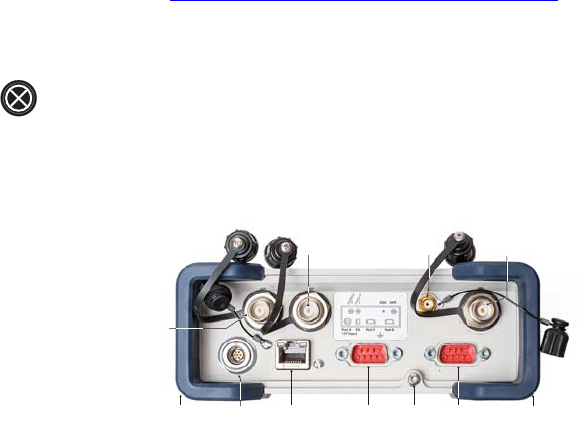
Rear Panel
•[8]: Bumpers (x2).
•[9]: GNSS input #1. A TNC coaxial female connector
allowing you to connect the first GNSS antenna to the
receiver via a coaxial cable.
•[10]: GNSS input #2. A TNC coaxial female connector
allowing you to connect the second GNSS antenna to the
receiver via a coaxial cable.
•[11]: External GSM antenna (optional). A coaxial female
connector (SMA type) allowing you to connect an external
cellular antenna.
The SP90m having a built-in GSM antenna, no external
GSM antenna is usually required. In case of adverse
reception conditions however (e.g. SP90m mounted in a
rack), an external antenna can advantageously be used for
better reception. Run the Web Server (Receiver> Network>
Modem> Modem Antenna) to choose which of the internal or
external antenna should be used.
The SP90m uses a GSM antenna when it sends or receives
RTK or differential corrections via its GSM modem.
•[12]: UHF radio connector. A TNC coaxial female
connector allowing you to connect a radio whip antenna.
This connector is available only if the SP90m has been
fitted with an internal radio.
Warning! Do not confuse this coaxial connector with the
GNSS inputs. Connecting a GNSS antenna to the UHF
[9]
[13] [17][16][14] [15]
[10] [11] [12]
[8] [8]

12
connector might damage it if the embedded UHF
transmitter is used (however the transmitter will not be
transmitting until there are enough GNSS satellites
tracked and used).
•[13]: DC Power input and serial port A (RS232). A seven-
contact, female connector allowing the SP90m to be
powered from either the provided AC adapter (connect the
cable extension between SP90m and the end of the AC
adapter output cable), or an external 9- to 36-V DC power
source through cable P/N 730477 (e.g. base setup using
an external radio transmitter).
•
[14]
: Ethernet connector. A 7-contact female connector
(RJ45) allowing you to connect the SP90m to a local
network (LAN). Through this connection, you may remotely
control and monitor SP90m operation from any computer
connected to the Internet. Data may also flow through this
connection, in the same way as through a serial port.
•[15]: RS232 serial port F, a SubD, nine-contact, male
connector. The PPS signal and the not operational yet
CAN bus are also available on this connector.
•[16]: Earth terminal. A screw terminal for connecting the
receiver chassis to Earth.
Electric Isolation: All signals available on the following
connectors are optically isolated from the receiver’s
internal circuitry and chassis ground, as well as from each
other:
• Serial ports A, B and F (including DC power output
voltage on port A)
• Ethernet port
•USB port
•[17]: Switchable RS232/RS422 serial data port B
(default is RS232), a SubD, nine-contact, male
connector. The External Event input is also present on this
connector.
13
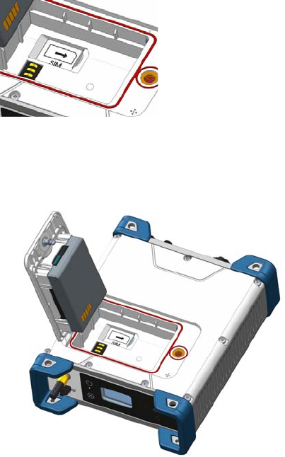
SIM Card The SIM card slot is located under the battery. Open the
battery compartment (see page 13) and then insert the SIM
card as shown below. Gently push the card to the right until
you hear a click.
To extract the SIM card, gently push it a bit further in. This
releases it from the slot. Just let go before extracting the SIM
card from the battery compartment.
Battery Model &
Battery
Compartment
The battery used is a Lithium-Ion 7.4-V DC - 3700 mAh
rechargeable battery. It is housed in a compartment
accessible from above the SP90m.
The battery door can be opened by lifting and then turning
the quarter-turn wing nut counter-clockwise.
The battery must first be inserted in the battery door (see
picture) and then you can close and lock the battery door. The
battery will smoothly connect to the receiver when closing the
battery door.
The battery will automatically operate as a backup power
source for the receiver if for some reason the external DC
source used was removed from the DC power input.

14
Conversely, the battery will be charged by the external power
source when needed. Indications are provided to report
battery charging when this happens (see page 9).
NOTE: If you are using a SIM card, you must insert it before
inserting the battery. (See page 13).
Buzzer The internal buzzer will sound whenever an error is detected.
The buzzer will sound six times and then stop. The error icon
will however continue to blink. To acknowledge the error
notification, go back to the General Status screen (see
page 28) and then press OK.
The buzzer can be deactivated permanently from the front
panel screen. Go to Display Settings, then go down into the
options until Buzzer is displayed. From there you can disable
the buzzer. Refer to page 36 as well.
Port Pinouts USB Port
On front panel, USB OTG “mini-B” connector.
5-C connector, fitted with sealing cap.
Pin Signal Name
1 USB ID
2GND
3 Device (D+)
4 Device (D-)
5 Host (VBus)
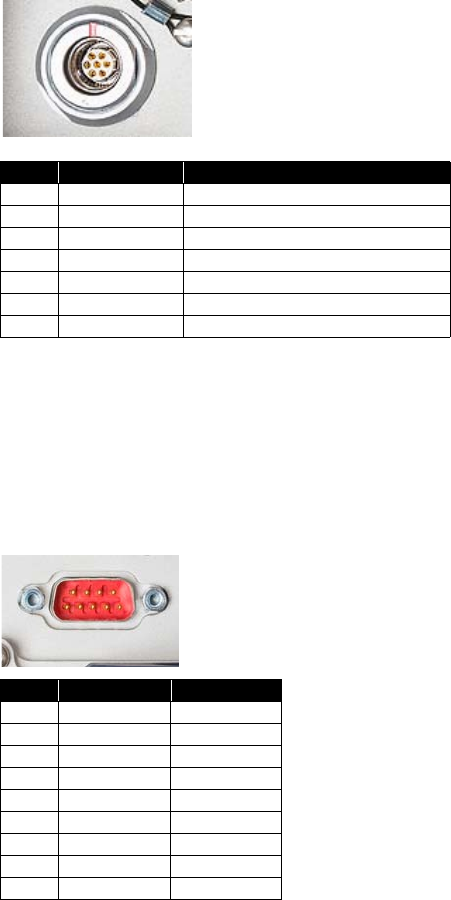
15
Power In, Serial Port A
On rear panel. A 7-C Connector.
NOTE: All signals are electrically isolated from the chassis
ground and power source.
Serial Port B
On rear panel. A switchable RS232/RS422 serial port +
external event input.
A 9-C connector fitted with a sealing cap.
Pin Signal Name Description
1 GND-A External Power Ground
2 PWR External Power Input (9-36 V DC)
3 TXD Port A RS232 TXD
4 RTS Port A RS232 RTS
5 CTS Port A RS232 CTS
6+Power in
7 RXD Port A RS232 RXD
Pin RS232 RS422
1NC NC
2 RX (IN) RX+ (IN)
3 TX (OUT) TX– (OUT)
4NC NC
5 GND-B GND-B
6NC NC
7 RTS (OUT) TX+ (OUT)
8 CTS (IN) RX– (IN)
9 EVENT EVENT (IN)
16
Port B can be switched to RS232 or RS422 using the
$PASHS,MDP command. RS232 inputs/outputs are typically
± 10 Volt asymmetrical signals with respect to ground.
RS422 inputs/outputs are 0/+5 Volt symmetrical signals
(differential lines).
NOTE: All signals are electrically isolated from the chassis
ground and power source.
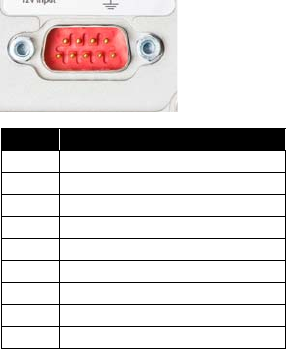
Serial Port F
On rear panel. A standard RS232 serial port + CAN bus +
1PPS output.
A 9-C connector fitted with a sealing cap.
The 1PPS output is similar to a standard TTL output (0/+5 V):
• VOH Min= 4.5 V at IOH = + 4 mA
• VOL Max= 0.4 V at IOL= - 4 mA
NOTE: All signals are electrically isolated from the chassis
ground and power source.
Pin Signal Name
1 CAN POWER (IN)
2RX (IN)
3TX (OUT)
4CANH
5 GND-F
6NC
7CANL
8NC
9 1PPS (OUT)