TRIMBLE EUROPE 110610 GSM/GPRS/UMTS/HSPA Module User Manual SP90MUG
TRIMBLE EUROPE BV GSM/GPRS/UMTS/HSPA Module SP90MUG
Contents
- 1. Host user manual 1_SP90M_UG_B_Draft2_en-v1a.pdf
- 2. Host user manual 1_SP90M_UG_B_Draft2_en-v1b.pdf
- 3. Host user manual 2_SP90M_UG_B_Draft2_en-v2.pdf
- 4. User guide_SP85_UG_A_en-part2_Part1
- 5. User guide_SP85_UG_A_en-part2_Part2
- 6. User guide_SP85_UG_A_en-part2_Part3
- 7. User guide_SP85_UG_A_en-part2_Part4
Host user manual 2_SP90M_UG_B_Draft2_en-v2.pdf

43
Power-Off Screen Hold down the Power button for a few seconds. The Spectra
Precision logo will appear on the screen.
After a few seconds, the message “Powering off...” will follow,
indicating that the receiver is being turned off.
If the anti-theft protection is still enabled when you ask for
receiver power-off, a message will ask you to confirm your
request.
If you wish to keep using the anti-theft protection, press OK
and then the receiver will complete the power-off sequence
as described above.
If you want to remove the anti-theft protection before turning
off the receiver, press Escape, go back to Advanced Settings to
remove the anti-theft protection (see page 37). Then you can
turn off the receiver as explained above.
44
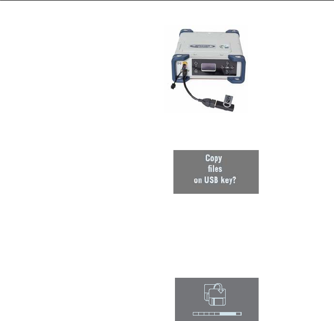
Using a USB Key
To Copy Files Whenever you connect a USB key to the receiver via cable
P/N107535, the following screen is displayed:
This screen is displayed for a few seconds. If you press OK
while this screen is still displayed, all the G-files and log files
stored in the receiver will be copied to the root folder on the
USB key (or will overwrite the files with same name).
Otherwise the copy operation will be skipped and the receiver
will come back to the General Status screen. The screen looks
like this while the files are being copied.
The same will happen if you power on the receiver with a USB
key already connected to the receiver.
To Upgrade the
Firmware
When a new firmware upgrade is available, it is easy to install
the new firmware using a USB key.
• Use your computer to copy the installation file (a *.tar file)
to the root directory of the USB key.
• The receiver being turned off, connect the USB key to the
receiver through cable P/N 107535 (provided).
• Press the OK button and the Power button simultaneously
for a few seconds. This starts the upgrade.
195
45
The screen will read successively:
{Spectra Precision logo}
USB Upload
Upgrading Firmware Step 1/5
Upgrading Firmware Step 2/5
Upgrading Firmware Step 3/5
Upgrading Firmware Step 4/5
Upgrading Firmware Step 5/5
Upgrading Firmware Complete
{Booting: Spectra Precision logo}
{Regular receiver startup to General Status screen}
Let the receiver proceed with the upgrade. Do not turn off
the receiver while the upgrade is in progress.
NOTE: If there is no USB key connected or the key does not
contain any firmware upgrade file, then the process will abort
after a few seconds.
Because data has to be decompressed on the USB key during
an upgrade, the USB key must be unlocked, with at least 100
MBytes of free memory, before starting the upgrade. The
upgrade will fail if there is not enough free space on the key.

46
Getting Started With the Web Server
Introduction to the
Web Server
Description and Function
The Web Server is a receiver-embedded, HTML-based
firmware application, designed to enable the receiver owner
(the “administrator”) to monitor and control the SP90m
GNSS receiver through a TCP/IP connection.
Running the Web Server for the First Time
As the receiver owner, after establishing a TCP/IP connection
between your computer and the receiver (via its Ethernet port
or via WiFi; see page 52 and page 47), do the following:
• Run a web browser on your computer.
• Type the IP address (or host name) of the receiver in the
web browser, then press the Enter key (see page 51).
This will launch the Web Server in the receiver, which in
turn will open a web page in the web browser.
Depending on how the Web Server has been configured,
you may be asked to log in. The first time you launch the
Web Server, use the default connection profile (the
“administrator profile”) to log in. This profile is the
following:
– Username: admin
– Password: password
You can customize the administrator profile by changing
the username and password. The Web Server will let you
do this from its Security page (see on-line Help file
attached to this page).
Security
The receiver owner may restrict the access to the Web Server
by implementing one of the three possible security levels
described below, sorted from the highest to the lowest
security level:
1. Enabled: On launching the Web Server, the user is
requested to log in by entering a username and password.
After having logged in, the user has full control over the
receiver (operation monitoring, access to configuration).
As the administrator, you may decide to share the
administrator profile (username and password) with other
trustworthy users. You may also create new connection
profiles for some other authorized users using $PASH
commands.

47
Remember that registered users have exactly the same
rights as the administrator, including managing users
through $PASH commands.
2. Enabled with Anonymous Access: Anyone who has been
given the IP address or host name of the receiver has
direct access to the Web Server (no log-in required). Only
receiver monitoring is allowed in this case. An anonymous
user CANNOT change the receiver configuration.
After the Web Server has been launched with this level of
security, the administrator, or any other authorized user,
can log in on the Security page (see on-line Help attached
to this web page).
3. Disabled: No security is implemented with this option.
Anyone who has been given the IP address or host name
of the receiver has direct access to the Web Server, both
for monitoring the receiver or changing its configuration.
With this low protection level, the receiver owner will be
well-advised to keep the receiver IP address or host name
as confidential as possible.
WiFi-Based TCP/IP
Connection
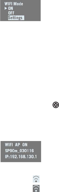
Setting Up the WiFi Device
• If the WiFi device has been turned off, it first needs to be
turned back on:
– On the receiver front panel, press one of the horizontal
keys until you see the WiFi screen.
–Press OK.
– Select ON:
–Press OK again. After a few seconds the screen
displays “WiFi ... ON”.
48
• Then you should indicate how the WiFi device will be
power-controlled and whether it will operate as a WiFi
client, as WiFi access point or both. Follow the steps
below:
– The previous screen being still displayed, press OK.
– Select Settings:
–Press OK again.
– Choose a power mode for the WiFi device: press OK,
select either Manual or Automatic (see explanations on
page 35 before making a choice) and then press OK.
– Press any of the vertical keys and then press OK.
– Choose an operating mode for the WiFi device: select
either Client, Access Point or AP and Client, depending on
the use case (see the next three sections below) and
then press OK.
– On your laptop or smart phone, start searching for WiFi
devices. When your SP90m receiver has been found,
select it and then enter the WiFi key (by default the
receiver serial number) to allow a WiFi connection with
the receiver.
– Back on receiver side, press to go back to the WiFi
“root” screen. If you have selected Access Point or AP
and Client, you will be able to read the IP address of the
WiFi access point in the lower line. Type in this IP
address (fixed, static address: 192.168.130.1) in your
computer or smart phone’s web browser to launch the
receiver’s Web Server.
When a WiFi connection is active, one or two of the
following icons appear on the General Status screen:
The first one indicates that the WiFi device is used as
an access point and the second one as a client.
49
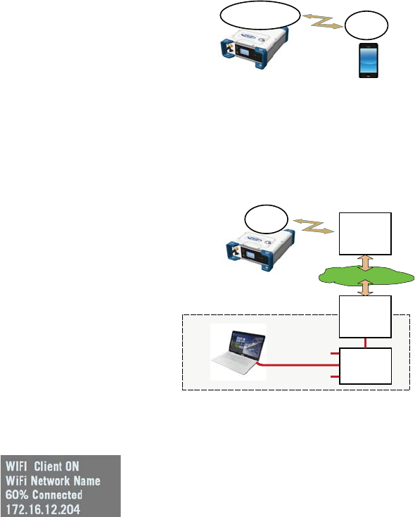
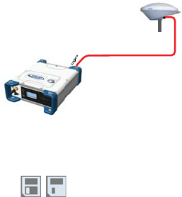
Using the WiFi Device as Access Point
Use the receiver’s WiFi device as access point in the following
cases:
• You want to access the Web Server from any WiFi-capable
device such as a computer or a mobile device (e.g. smart
phone).
• You are located within WiFi range of the SP90m.
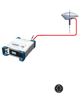
Using the WiFi Device as Client
Use the receiver’s WiFi device as client in the following cases:
• You want a remote access to the Web Server and Internet
is easily accessible from the location where you are.
• The SP90m is operated in a location where only a local
WiFi network is available.
To select a WiFi network, you have to run the Web Server:
• Go to Receiver> Network> WiFi
• Unless already done, turn on the WiFi device, select the
client mode and click Configure.
• Scan for WiFi networks, select one and then connect to it.
The WiFi screen on the receiver should look as shown.
WiFi
Access Point WiFi
Client
Public Internet
Ethernet cable
Hub or
Switch
Local Network
Gateway
or ADSL
Modem
WiFi
Local
Network
WiFi
Client
Remote User
50
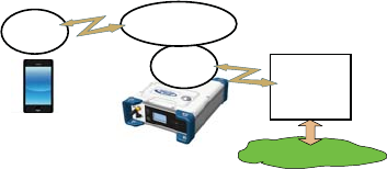
Using the WiFi Device as both Access Point and Client
Use the receiver’s WiFi device as both access point and client
in the following cases:
• You want to access the Web Server from your computer or
smart phone.
• The SP90m is configured to receive or transmit
corrections over the Internet via WiFi.
• You are located within WiFi range of the SP90m.
In this use case, the Web Server will be run from the smart
phone via the receiver’s WiFi device used as access point,
whereas corrections will be routed over the Internet using the
receiver’s WiFi device as client.
Ethernet-Based
TCP/IP Connection
In this use case, you will have to use a standard Ethernet
cable (fitted with an RJ45 connector at either end) to connect
the receiver to the local network.
To make this connection successful, you may have to take
advice from your IT expert, depending on the local IP network
environment. You should inform this person of the following
before proceeding:
• The SP90m is not fitted –and cannot be fitted– with a
firewall. If a firewall is needed in your local network, it
should be installed on a device other than the SP90m.
• HTTP port #80 is used by default in the receiver to access
the Web Server.
The choice of using the DHCP mode or not within the local
network is also the decision and responsibility of the IT
expert.
Typically, there are two possible cases of TCP/IP connection:
• TCP/IP connection within a local network.
• TCP/IP connection through the public Internet.
These are detailed in the sections below.
NOTE: It is assumed that the reader knows how to send
$PASH commands to the receiver.
Public Internet
WiFi
Local
Network
WiFi
Client
WiFi
Access Point
WiFi
Client
Data
Web Server

51
Setting Up the Ethernet Device
• If the Ethernet device has been turned off, you first need
to turn it back on:
– On the receiver front panel, press one of the horizontal
keys until you see the Ethernet screen.
–Press OK.
– Select ON:
–Press OK again. After a few seconds the screen
displays “Ethernet ON”.
• Then you should indicate whether the receiver will be
assigned a static IP address (DHCP off) or a dynamic IP
address (DHCP on). If you don’t know which option to use,
ask your local IT expert. Follow the steps below:
– The previous screen being still displayed, press OK.
– Select Settings:
–Press OK again.
– Choose the desired option and then press OK.
– If you chose DHCP Mode: ON, there is nothing else to be
done.
If you chose DHCP Mode: OFF, press one of the vertical
arrows to access the Static Address screen. Press OK
and then enter successively each of the figures making
up the static IP address. Press OK when you are done.
When the IP connection is active, the icon below
appears on the General Status screen:
NOTE: If you activate DHCP and there is no DHCP server
in your network responding to the request, a static IP
address (of the type 169.254.1.x) will be automatically
assigned to the receiver (and displayed on the Ethernet
screen). This is the IP address you should choose to
connect to.
52
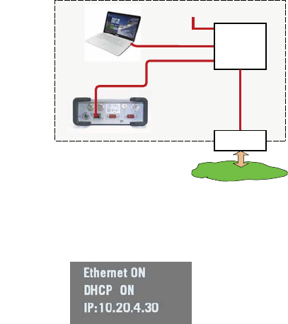
TCP/IP Connection Within a Local Network
In this use case, the receiver and the computer are connected
to the same local area network (LAN) and may even be in the
same room. Here the communication will not take place
through the public Internet, but simply within the local
network.
The connection diagram typically is the following.
The valid receiver IP address is the one shown in the lower
line on the Ethernet screen.
Example indicating the IP address to use with DHCP On:
Local Network
Ethernet cable
Ethernet cable
Hub or
Switch
Gateway or
ADSL Modem
Public Internet
Ethernet port
SP90m
Local User
53
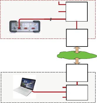
TCP/IP Connection Through the Public Internet
In this use case, the receiver and computer are connected to
different local networks. Here the communication will
necessarily take place through the public Internet.
The connection diagram typically is as follows.
In this configuration, the IT expert should take all the
necessary steps for the receiver owner to be able to access the
SP90m through the public IP address of the local network. In
this case, the IP address shown on the receiver display screen
is NOT the one to be entered in the web browser.
It is therefore the responsibility of the IT expert to provide the
appropriate connection information:
<IP address:port number> or host name
Public Internet
Ethernet cable Hub or
Switch
Public IP address
Local Network
Local Network
Ethernet cable
Hub or
Switch
Gateway
or ADSL
Modem
Gateway
or ADSL
Modem
Ethernet port
SP90m
Remote User
54
Introduction to
Multi-Operating
Mode
The SP90m is a multi-application GNSS receiver, making it
possible to use different operating modes simultaneously.
The limitation to that feature is very simple to understand:
The maximum number of baselines the SP90m can calculate
simultaneously is 3. The capability for the SP90m to support
several operating modes simultaneously is simply derived
from that statement.
NOTE: Working in a Trimble RTX mode does not “consume” a
baseline, which means that the above statement would be
more accurate if we said, “The maximum number of baselines
the SP90m can calculate simultaneously is 3 + RTX”.
The consequences of this rule are as follows:
• In single-antenna configuration:
– In Hot Standby RTK, you can configure the receiver to
use up to three independent correction sources (=
three baselines), thus making it possible to have up to
two different backup position solutions available in
case the first source of position solution fails.
– In Hot Standby RTK + Relative RTK, you can only set
two independent correction sources (= two baselines),
to have a backup position solution available in case the
first source of position solution fails. The third baseline
is dedicated to the Relative RTK mode.
• In a two-antenna configuration, the heading mode may be
combined with all of the existing rover modes:
– Autonomous
–RTK
– Hot Standby RTK
– RTK + Relative RTK
– Only Relative RTK
–Dual RTK
– Dual Relative RTK
However, in Hot Standby RTK, there can only be two
independent sets of corrections used (not three because
one baseline is dedicated to computing heading).
Besides, the rover and moving base modes can be run
simultaneously. To make this work, you should first configure
the receiver as a rover, then as a moving base (and not the
other way round). That way, while base corrections will be
generated and delivered via your programmed output
messages, the receiver will continue to compute RTK
positions for its own location provided the required external
corrections continue to enter the receiver.

55
Using SP90m With a Single Antenna
The reader is supposed to know how to run the Web Server
(see Getting Started With the Web Server on page 46) and
how to use the receiver user interface (see Receiver User
Interface on page 26) before reading this section.
Remember, when using the Web Server, at any time you can
access context-sensitive help by pressing this key:
Specifying the
Model of Antenna
Used
When using one single GNSS antenna connected to SP90m,
only GNSS input #1 can be used. GNSS input #2 must not
be used in a single GNSS antenna setup.
The setting described below is required prior to configuring
the receiver in any of the operating modes described in the
following sections.
Use the Web Server to specify the model of antenna
connected to GNSS input #1:
• Go to Receiver > Position > Sensors/Antennas Setup.
• Set Multi-Sensor Mode to Single Antenna.
• Choose the point on the antenna for which you want the
SP90m to compute the position (L1 phase center, ARP or
ground mark).
• Describe the model and height of antenna used as the
primary antenna:
– Manufacturer
– Antenna name and its RINEX name.
– Method used to measure the antenna height (i.e.
choice of the point on the antenna from which the
height measurement is performed).
– Value of measured distance according to the chosen
antenna height measurement method.
NOTE: Entering the height makes sense if you want to get
the position of the ground mark or if you enter the ground
mark coordinates as a base’s reference position.
• Keep the secondary antenna defined as UNKNOWN.
•Press Configure. The antenna model is now set.
NOTE: When configuring a static base from the receiver front
panel, you will be able to select the model of antenna used (for
the primary antenna). By default, if you leave the base mode
to operate the receiver as a rover, the receiver will assume this
antenna model is still used in the rover configuration
.
56
Raw Data
Recording
On the receiver’s General Status screen, the following icons
will appear in succession at a rate of 1 second when the
receiver is actually collecting raw data:
Using the Web Server
Using the Web Server to launch data recording is particularly
suitable for remote-controlled, static raw data collection.
• Go to Receiver > Memory.
• Enable Data Recording.
• Enter a site name for the location occupied by the
receiver.
• Choose the memory where to save the raw data file.
• Choose a recording interval in Hz. Additionally, you may
ask the receiver to record the “TTT” message resulting
from the advent of any incoming external event and/or the
“PTT” message providing the time-tagging of the PPS
signal.
• Click Configure. The receiver starts recording the default
messages programmed on port M (as listed after Data
type). To change the content of this message, refer to Raw
Data Recording on page 77).
In the right part of the Memory tab screen, at the bottom
of the list of files stored in the selected memory, you can
now see – shown in red – the name of the file being
created.
Working from the Receiver Front Panel
Working from the receiver front panel to launch data
recording allows a rover operator to choose between “Static”
or “Stop & Go” data collection. A USB key connected to the
receiver front panel may be used to save the raw data file
once created.
• Press one of the horizontal keys until you see the “Record
OFF” screen.
1
GNSS Raw Data
Acquisition
57
•Press OK.
• Choose the option that suits your requirements in terms of
data collection type (Static or Stop & Go), the storage
location (Mem or USB) used to save the file, then press
OK.
This starts the data recording. Refer to Raw Data
Recording on page 42 to learn more about the workflow
used.
Autonomous or
SDGPS (SBAS)
Rover
On the receiver’s General Status screen, the receiver will
display “AUTO” or “SDGPS” when computing a position
respectively in autonomous or SDGPS mode. The computed
position is diplayed after pressing .
Use the Web Server to configure the receiver:
• Go to Receiver > Position > Rover Setup
• Set Processing Mode to Autonomous
• Additionally, in the Other Settings section, you may change
the primary GNSS system used (GPS is the default
selection), limit the level of position accuracy to SBAS
Differential Position or Standalone Position.
• Select the model of dynamics that suits the movement
pattern of your rover best.
• Click Configure. The receiver starts operating in
autonomous mode. If SBAS satellites are received, the
receiver will be able to deliver positions with SBAS
Differential accuracy (provided SBAS is enabled; see
Receiver > Satellites).
1
XYZ or
Lat-Lon-Height
Position
58
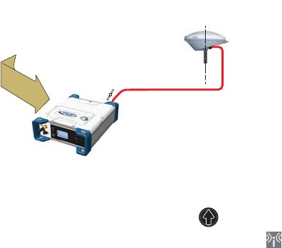
RTK or DGPS Rover
On the receiver’s General Status screen, the receiver will
display “FIXED” (with short “FLOAT” transition time) or
“DGPS” when computing a position respectively in RTK or
DGPS mode. The computed position is displayed after
pressing .
When corrections are received and used, is displayed on
the General Status screen together with the age of corrections
(see General Status on page 28).
To configure the receiver as a DGPS or RTK rover, use the Web
Server as follows:
• Go to Receiver > Position > Rover Setup.
• Set Processing Mode to RTK.
• Select how the corrections are being transmitted to the
receiver by setting Input Mode accordingly. If you choose
Automatic, the receiver will find by itself which of its ports
is used to acquire corrections. If you choose Manual, you
need to specify this port.
• Additionally, in the Other Settings section, you may change
the primary GNSS system used (GPS is the default
selection), limit the level of position accuracy to less than
what the receiver can actually achieve in this case.
Typically you will choose RTK Position or (RTCM) Differential
Position to match with the selected operating mode
(respectively RTK or DGPS).
• Select the model of dynamics that suits the movement
pattern of your rover best.
• Click Configure.
• Set the device used by the receiver to acquire corrections:
– If corrections are received via radio, go to Receiver >
Radio to enter all radio parameters. You may use the
internal radio or an external radio.
1
XYZ or
Lat-Lon-Height
Position
One set of corrections via:
• Internet (Ethernet, cellular modem, or WiFi), or
• UHF Radio
59
– If corrections are received over the Internet, go to
Receiver > Network to set the device used (this may be
Ethernet, Modem or WiFi; more information about how
to set up theses devices can be found in the relevant
context-sensitive Help). Then go to Receiver > I/Os to
start data reception in NTRIP or Direct IP mode.
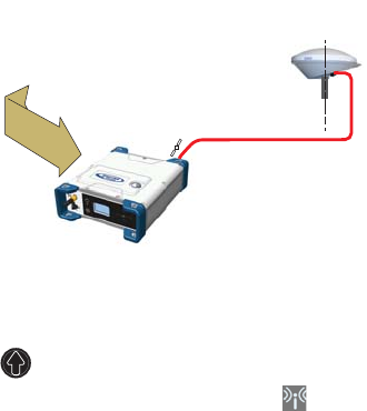
Hot Standby RTK
Rover
Hot Standby RTK is similar to RTK except that two or three
independent sets of corrections are received instead of one.
The receiver will choose the best of the two or three sets of
corrections in order to improve position availability and
accuracy.
On the receiver’s General Status screen, the receiver will
display “FIXED” (with short “FLOAT” transition time) when
computing a position in Hot Standby RTK mode. The
computed position is diplayed after pressing .
When at least one set of corrections is received and used,
is displayed on the General Status screen together with the
age of corrections (see General Status on page 28). The
displayed age of corrections is always that of the corrections
actually used in the position computation.
To configure the receiver as a Hot Standby RTK rover, use the
Web Server as follows:
• Go to Receiver > Position > Rover Setup.
• Set Processing Mode to Hot Standby RTK.
• Select how the two (or three) sets of corrections are being
transmitted to the receiver by setting Input Mode
accordingly. If you choose Automatic, the receiver will find
by itself which of its ports are used to acquire the sets of
corrections. If you choose Manual, you need to specify
each of the ports used.
• Additionally, in the Other Settings section, you may change
the primary GNSS system used (GPS is the default
1
XYZ or
Lat-Lon-Height
Position
Two independent sets of corrections via:
• Internet (Ethernet, cellular modem, or WiFi), or
• UHF Radio
60
selection), limit the level of position accuracy to less than
what the receiver can actually achieve in this case.
Typically you will choose RTK Position to match with the
selected operating mode.
• Select the model of dynamics that suits the movement
pattern of your rover best.
• Click Configure.
• Set the device used by the receiver to acquire the two sets
of corrections:
– If corrections are received via radio, go to Receiver >
Radio to enter all radio parameters. You may use the
internal radio or an external radio.
– If corrections are received over the Internet, go to
Receiver > Network to set the device used (this may be
Ethernet, Modem or WiFi; more information about how
to set up theses devices can be found in the relevant
context-sensitive Help). Then go to Receiver > I/Os to
start data reception in NTRIP or Direct IP mode.
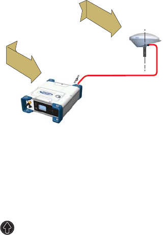
Trimble RTX Rover
Using a Trimble RTX service in the SP90m requires that you
first buy a subscription to this service. On the other hand, the
receiver is ready to operate in Trimble RTX mode (dedicated
firmware option has been pre-installed at the factory)
provided an L-band capable GNSS antenna is used.
On the receiver’s General Status screen, the receiver will
display “RTX” when computing a position using a Trimble
RTX service. The computed position is displayed after
pressing .
1
X-Y-Z or
Lat-Lon-Height
Position
Trimble RTX service
via IP or satellite
61
To configure the receiver in RTX, use the Web Server as
follows:
• Go to Receiver > Position > Rover Setup.
• Choose the channel through which RTX corrections enter
the receiver by setting Corrections Source accordingly:
– If you choose Automatic, the receiver will find by itself
which channel to use (L-Band or NTRIP).
– If you choose L-Band, the receiver will expect RTX
corrections to come from a satellite.
– If you choose NTRIP, the receiver will expect RTX
corrections to come from the Internet.
NOTE: RTX corrections will come from the Internet only
after you have taken all the steps to implement an active
IP connection, either via GSM, WiFi or Ethernet. The
connection to the remote RTX service will then be
automatic.
• Set Engine Mode to ON.
• Select the datum and plate in which to deliver the
coordinates of the computed position:
– If you select OFF, the position will be expressed in the
ITRF2014 current epoch datum.
– If you select ON, choose a datum and a tectonic plate.
• Additionally, in the Other Settings section, you may change
the primary GNSS system used (GPS is the default
selection), limit the level of position accuracy to less than
what the receiver can actually achieve in this case.
Typically you will choose PPP Position to match with RTX.
• Select the model of dynamics that suits the movement
pattern of your rover best.
• Click Configure.
WARNING: The way you set Processing Mode is very important
here. If for example it is set to RTK and every step has been
taken to have RTK corrections available (see page 58), then
the receiver will automatically choose between RTX and RTK
depending on which of these two modes is providing the best
position solution. You will be able to know which mode is
currently used by taking a look at the receiver’s General
Status screen.
62
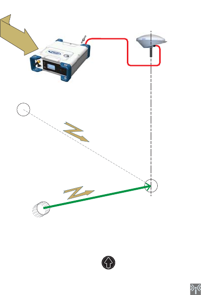
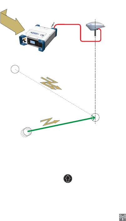
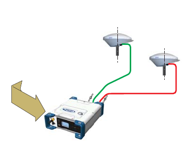
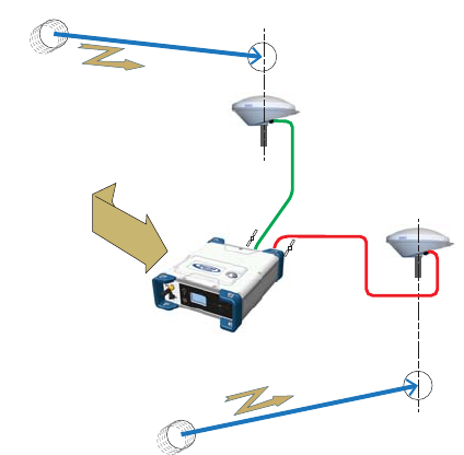
RTK + Relative
RTK Rover
Reminder: Relative RTK refers to the ability of the SP90m to
compute and deliver the three components of the vector
connecting a mobile base to this receiver. The components of
the vector are provided with centimeter accuracy, just as is
the position of the SP90m, as computed in RTK using
corrections received from a static base.
One of the typical applications of Relative RTK is the
constant monitoring of the position of a vessel relative to that
of another vessel or to the jib of a crane used on a quay.
On the receiver’s General Status screen, the receiver will
display “FIXED” (with short “FLOAT” transition time) when
computing a position in RTK mode. The computed RTK
position is diplayed after pressing . A new press on this
button will display the components of the vector.
When at least one set of corrections is received and used,
is displayed on the General Status screen together with the
age of corrections (see General Status on page 28).
To configure the receiver in RTK+Relative RTK, use the Web
Server as follows:
• Go to Receiver > Position > Rover Setup.
• Set Processing Mode to RTK + Relative RTK.
1
XYZ or
Lat-Lon-Height
Position
+
3-D Components
of Vector
RTK
Position
3-D Vector
Two independent sets of corrections via:
• Internet (Ethernet, cellular modem, or WiFi), or
• UHF Radio
Corrections
from static base
to compute
RTK position
Corrections
from moving base
to compute
3D-vector
63
• Select how the two sets of corrections are being
transmitted to the receiver by setting Input Mode
accordingly.
If you choose Automatic, the receiver will find by itself
which of its ports are used to acquire the two sets of
corrections.
If you choose Manual, you need to specify these two ports.
The “BRV” line defines the port routing the corrections
from a moving base allowing vector computation whereas
the “RTK” line defines the port routing the corrections
from a static base allowing position computation.
• Additionally, in the Other Settings section, you may change
the primary GNSS system used (GPS is the default
selection), limit the level of position accuracy to less than
what the receiver can actually achieve in this case.
Typically you will choose RTK Position to match with the
selected operating mode.
• Select the model of dynamics that suits the movement
pattern of your rover best.
• Click Configure.
• Set the device used by the receiver to acquire the two sets
of corrections:
– If corrections are received via radio, go to Receiver >
Radio to enter all radio parameters. You may use the
internal radio or an external radio.
– If corrections are received over the Internet, go to
Receiver > Network to set the device used (this may be
Ethernet, Modem or WiFi; more information about how
to set up theses devices can be found in the relevant
context-sensitive Help). Then go to Receiver > I/Os to
start data reception in NTRIP or Direct IP mode.
64
Hot Standby RTK+
Relative RTK
This mode is similar to RTK+Relative RTK (see page 62)
except that the RTK position is a “Hot Standby RTK” one (see
also page 59). The combination of these two modes may be
summarized as shown in the diagram below.
On the receiver’s General Status screen, the receiver will
display “FIXED” (with short “FLOAT” transition time) when
computing a position in Hot Standby RTK mode. The
displayed age of corrections is always that of the corrections
actually used in the position computation. The computed
position is diplayed after pressing .
The components of the vector are visible in the Web Server
(in Receiver > Position > Vectors tab on the right) or by
programming an NMEA VCR or VCT message on one of the
receiver ports (see Web Server’s I/Os tab).
When at least one set of corrections is received and used,
is displayed on the General Status screen together with the
age of corrections (see General Status on page 28).
To configure the receiver in Hot Standby RTK + Relative RTK,
use the Web Server as follows:
• Make sure the Heading mode is off.
• Go to Receiver > Position > Rover Setup.
• Set Processing Mode to Hot Standby RTK + Relative RTK.
1
XYZ or
Lat-Lon-Height
Position
+
3-D Components
of Vector
Hot Standby RTK
Position
3-D Vector
Three independent sets of corrections via:
• Internet (Ethernet, cellular modem, or WiFi), or
• UHF Radio
Two sets of corrections
from static base
to compute
RTK position
Corrections
from moving base
to compute
3D-vector
65
• Select how the three sets of corrections are being
transmitted to the receiver by setting Input Mode
accordingly.
If you choose Automatic, the receiver will find by itself
which of its ports are used to acquire the three sets of
corrections.
If you choose Manual, you need to specify these three
ports. The “BRV” line defines the port routing the
corrections from a moving base allowing vector
computation, whereas the “Standby RTK” lines define the
ports routing the corrections (from one or two static
bases), allowing position computation.
• Additionally, in the Other Settings section, you may change
the primary GNSS system used (GPS is the default
selection), limit the level of position accuracy to less than
what the receiver can actually achieve in this case.
Typically you will choose RTK Position to match to the
selected operating mode.
• Select the model of dynamics that suits the movement
pattern of your rover best.
• Click Configure.
• Set the device used by the receiver to acquire the three
sets of corrections:
– If corrections are received via radio, go to Receiver >
Radio to enter all radio parameters. You may use the
internal radio or an external radio.
– If corrections are received over the Internet, go to
Receiver > Network to set the device used (this may be
Ethernet, Modem or WiFi; more information about how
to set up theses devices can be found in the relevant
context-sensitive Help). Then go to Receiver > I/Os to
start data reception in NTRIP or Direct IP mode.
66
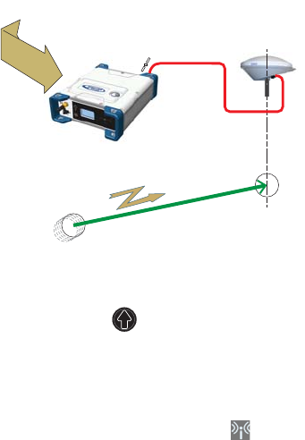
Relative RTK Rover Reminder: Relative RTK refers to the ability for the SP90m to
compute and deliver the three components of the vector
connecting it to a mobile base. The components of the vector
are provided with centimeter accuracy.
One of the typical applications of Relative RTK is the
constant monitoring of the position of a vessel relative to that
of another vessel or to the jib of a crane on a quay.
On the receiver’s General Status screen, the receiver will
display “AUTO” or “SDGPS” when computing a position in
standalone or SBAS mode. The computed position is
displayed after pressing .
The components of the vector are visible in the Web Server
(in Receiver > Position > Vectors tab on the right) or by
programming an NMEA VCR or VCT message on one of the
receiver ports (see Web Server’s I/Os tab).
When corrections are received and used, is displayed on
the General Status screen together with the age of corrections
(see General Status on page 28).
To configure the receiver in Relative RTK, use the Web Server
as follows:
• Go to Receiver > Position > Rover Setup.
• Set Processing Mode to Only Relative RTK.
• Select how the corrections are being transmitted to the
receiver by setting Input Mode accordingly. If you choose
Automatic, the receiver will find by itself which of its ports
are used to acquire the corrections. If you choose Manual,
you need to specify the port.
• Additionally, in the Other Settings section, you may change
the primary GNSS system used (GPS is the default
selection) or change the Output Position Type field. Be
1
3-D Components
of Vector
3-D Vector
One set of corrections from moving base via:
• Internet (Ethernet, cellular modem, or WiFi), or
• UHF Radio
Corrections
from moving base
to compute
3D-vector
67
aware the position computed in Relative RTK, in terms of
accuracy, is an SBAS Differential position at best.
• Select the model of dynamics that suits the movement
pattern of your rover best.
• Click Configure.
• Set the device used by the receiver to acquire the two sets
of corrections:
– If corrections are received via radio, go to Receiver >
Radio to enter all the radio parameters. You may use
the internal radio or an external radio.
– If corrections are received over the Internet, go to
Receiver > Network to set the device used (this may be
Ethernet, Modem or WiFi; more information about how
to set up theses devices can be found in the relevant
context-sensitive Help). Then go to Receiver > I/Os to
start data reception in NTRIP or Direct IP mode.
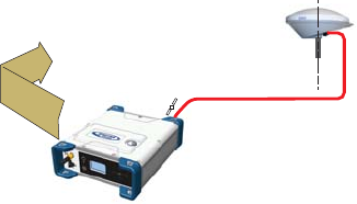
Static or Moving
Base
Using the Web Server
To configure the receiver as a base, use the Web Server as
follows:
• Go to Receiver > Position > Base Setup.
•Use the Station ID. field to enter the identification number.
Remember, the station ID should comply with the type of
correction data format it generates. As a reminder, this is
the list of authorized numbers in relation to the format
used:
– RTCM 2.3: 0-1023
– CMR/CMR+: 0-31
– ATOM & RTCM3.x: 0-4095
• Select whether the base is stationary (Static) or in motion
(Moving).
If you choose Static, you need to specify the exact location
of the base. You can do this in two different ways:
1
Base corrections delivered via:
• Internet (Ethernet, cellular modem, or WiFi), or
• UHF Radio
68
– Type in the three geographical coordinates (Latitude,
Longitude, Height) of the base, as well as the position
on the antenna (Reference Position) for which these
coordinates are given.
– Or click on the Get Current Position button to make the
currently computed position the new base position. In
this case, it is assumed that the receiver actually
calculates a position at the time you click the button.
As a result, the above three coordinates fields above
are overwritten with the current computed position,
and the Reference Position field is automatically set to
“L1 Phase Center”.
NOTE: The antenna height was entered when specifying
the number of antennas used (see page 55).
• Additionally, in the Other Settings section, you may change
the primary GNSS system used (GPS is the default
selection).
• Click Configure.
• Set the device used by the receiver to send out its
corrections:
– If corrections are broadcast via radio, go to Receiver >
Radio to enter all radio parameters. You may use the
internal radio or an external radio.
– If corrections are broadcast over the Internet, go to
Receiver > Network to set the device used (this may be
Ethernet, Modem or WiFi; more information about how
to set up theses devices can be found in the relevant
context-sensitive Help).
• You still have to set which corrections the base will
generate. This is detailed in Base Data Messages on
page 76.
NOTE: You may also set a base to use a virtual antenna. This
is required when a rover using the corrections from this base
has no information on the model of GNSS antenna used at
the base. In this case a virtual antenna can be used
(ADVNULLANTENNA or GPPNULLANTENNA). If you don’t
need a virtual antenna, just keep the Manufacturer field set to
OFF.
Working from the Receiver Front Panel
The receiver user interface offers an alternative to the Web
Server to set up a static base. Please follow the detailed
procedure described in Base Mode on page 39).

69
Using SP90m With Two Antennas
The reader is supposed to know how to run the Web Server
(see Getting Started With the Web Server on page 46), and
how to use the receiver user interface (see Receiver User
Interface on page 26) before reading this section.
Remember, when using the Web Server, at any time you can
access context-sensitive help by pressing this key:
Specifying the
Models of
Antennas Used
When using SP90m with two GNSS antennas, both GNSS
input #1 and GNSS input #2 are used.
The setting described below is required prior to configuring
the receiver in any of the operating modes described in the
sections that follow.
Use the Web Server to specify the models of antennas
connected to input #1 and input #2:
• Go to Receiver > Position > Sensors/Antennas Setup.
• Set Multi-Sensor Mode to Two Antennas or Two Antennas (L1
only on input#2) depending on the reception capability of
the model of antenna you connect to input #2.
• Choose the point on the antenna for which you want the
SP90m to compute the position (L1 phase center, ARP or
ground mark).
• For each of the two antennas (primary and secondary
antennas), describe the model and height of antenna
used:
– Manufacturer
– Antenna name and its RINEX name
– Method used to measure the antenna height (i.e.
choice of the point on the antenna from which the
height measurement is performed)
– Value of measured height according to the chosen
antenna measurement method.
NOTE 1: Entering the height only makes sense if you want
to get the position of the ground mark.
NOTE 2: Antenna heights are not required when
computing heading.
•Press Configure. The two antenna models are now set.
NOTE: When configuring a static base from the front panel,
you will be able to select the antenna model used for the
70
primary antenna. By default, if you leave the base mode to
operate the receiver as a rover, the receiver will assume this
antenna model is still used as the primary antenna. You
cannot choose an antenna model for the secondary antenna
using the front panel. This operation needs to be done within
the Web Server.
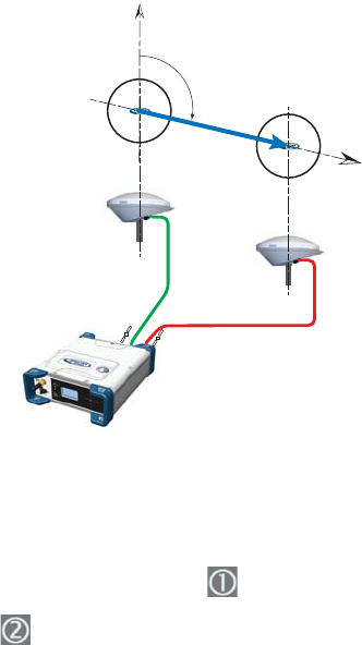
SP90m Delivering
Heading
Measurements
The receiver will measure the heading angle of the vector
connecting the secondary antenna to the primary antenna.
On the receiver’s General Status screen, the receiver will
display “AUTO” or “SDGPS” indicating that the position for
the primary antenna is either computed in autonomous or
SDGPS mode respectively.
Press one of the vertical keys to see the computed position
for the primary antenna (marked ) and the heading
screen. No position is computed for the secondary antenna
(marked ).
Use the Web Server to configure the receiver:
• Go to Receiver > Position > Heading Setup
• Set Mode to Heading. This automatically sets Input to
Internal.
•Use the Length Type field to choose the way you want the
receiver to specify the baseline, i.e. the distance between
the primary and secondary antennas:
1
2
N
Heading
Baseline Vector
71
– If it is assumed to be strictly fixed (the two antennas
are mounted on a unique, rigid support), select Fixed.
With this option, you may set the receiver to auto-
calibrate the heading computation. In this case keep
the Auto-Calibration option enabled. Or you may prefer
to disable this option, in which case you will have to
type in the exact length of the baseline, in meters (in
the Vector Length field).
– If you think it may slightly vary over time (due to
support deformation, presence of wind, etc.), select
Changing (Flex). If you choose this option, no auto-
calibration is required.
• Enter the possible two offsets in relation to your antenna
installation (see GNSS Antennas Setup for Heading
Measurements on page 19) as well as the maximum
expected vertical angle (Max. Baseline Elevation) the
baseline may present compared to the horizontal, and the
permitted tolerance on the baseline length (Baseline
Tolerance).
• Click Configure. The receiver starts operating in heading
mode.
Dual-RTK Rover The SP90m may be configured to provide two RTK positions,
one per antenna. These results can subsequently be used to
compute the heading angle resulting from the orientation of
the two antennas, while providing an accurate position for
each of these two antennas.
On the receiver’s General Status screen, the receiver will
display “FIXED” (with short “FLOAT” transition time) when
computing a position in RTK DGPS mode for the primary
antenna.
1
2
XYZ or
Lat-Lon-Height
Position
of primary
antenna
XYZ or
Lat-Lon-Height
Position
of secondary
antenna
One or two sets of corrections via:
• Internet (Ethernet, cellular modem, or WiFi) or
• UHF Radio

72
Press one of the vertical keys to see the computed position
for the primary antenna (marked ) and the secondary
antenna (marked ).
When corrections are received and used, is displayed on
the General Status screen together with the age of corrections
(see General Status on page 28).
To configure the receiver as a Dual RTK rover, use the Web
Server as follows:
• Go to Receiver > Position > Rover Setup.
• Set Processing Mode to Dual RTK.
• Select how the corrections are being transmitted to the
receiver by setting Input Mode accordingly.
If you choose Automatic, the receiver will find by itself
which of its ports are used to acquire corrections.
If you choose Manual, you need to specify each of the two
ports. The “RTK-1” line will define the port routing the
corrections allowing the receiver to compute the position
of the primary antenna, whereas the “RTK-2” line will
define the port routing the corrections allowing the
receiver to compute the position of the secondary
antenna.
NOTE: The same set of corrections, hence the same port,
can be used for both antennas.
• Additionally, in the Other Settings section, you may change
the primary GNSS system used (GPS is the default
selection), limit the level of position accuracy to less than
what the receiver can actually achieve in this case.
Typically you will choose RTK Position to match to the
selected operating mode.
• Select the model of dynamics that suits the movement
pattern of your rover best.
• Click Configure.
• Set the device used by the receiver to acquire corrections:
– If corrections are received via radio, go to Receiver >
Radio to enter all radio parameters. You may use the
internal radio or an external radio.
– If corrections are received over the Internet, go to
Receiver > Network to set the device used (this may be
Ethernet, Modem or WiFi; more information about how
to set up theses devices can be found in the relevant
context-sensitive Help). Then go to Receiver > I/Os to
start data reception in NTRIP or Direct IP mode.
73
Dual-Relative RTK
To configure the receiver as a Dual Relative RTK rover, use the
Web Server as follows:
• Go to Receiver > Position > Rover Setup.
• Set Processing Mode to Dual Relative RTK.
• Select how the corrections are being transmitted to the
receiver by setting Input Mode accordingly.
If you choose Automatic, the receiver will find by itself
which of its ports are used to acquire corrections.
If you choose Manual, you need to specify each of the two
ports and possibly the base antenna for which these
corrections are computed and delivered (select N/A for a
single-antenna base). The “BRV-1” line will define the port
routing the corrections from a moving base allowing the
receiver to compute the vector to the primary antenna,
whereas the “BRV-2” line will define the port routing the
corrections from a moving base allowing the receiver to
compute the vector to the secondary antenna.
NOTE: The same set of corrections from the same moving
base, hence the same port, can be used for both antennas.
• Additionally, in the Other Settings section, you may change
the primary GNSS system used (GPS is the default
selection), limit the level of position accuracy to less than
what the receiver can actually achieve in this case.
1
3-D Components
of Vector
3-D Components
of Vector
3-D Vector
One or two sets of corrections from moving base via:
• Internet (Ethernet, cellular modem, or WiFi), or
• UHF Radio
Corrections
from moving base
to compute
3D-vector
3-D Vector
Corrections
from moving base
to compute
3D-vector
2
74
Typically you will choose RTK Position to match to the
selected operating mode.
• Select the model of dynamics that suits the movement
pattern of your rover best.
• Click Configure.
• Set the device used by the receiver to acquire corrections:
– If corrections are received via radio, go to Receiver >
Radio to enter all radio parameters. You may use the
internal radio or an external radio.
– If corrections are received over the Internet, go to
Receiver > Network to set the device used (this may be
Ethernet, Modem or WiFi; more information about how
to set up theses devices can be found in the relevant
context-sensitive Help).

75
Programming Data Outputs
The reader is supposed to know how to run the Web Server
(see Getting Started With the Web Server on page 46) before
reading this section.
Remember, when using the Web Server, at any time you can
access context-sensitive help by pressing this key:
• Go to Receiver > I/Os > Input Setup and Output Messages.
In the right-hand part of the Web Server window, all
receiver ports are listed, and for each of them, you can
read the message or messages currently programmed to
be output on this port at the specified data rate(s).
• To add or modify a message on a port, click on the line
corresponding to that port. This updates the left-hand part
of the window from which you can add or modify as many
messages as you wish.
You may need to re-select the matching category in the
upper field to access the desired message. For example if
NMEA and ATOM messages are programmed on a given
port, re-select ATOM in the upper field to access the
definition of the ATOM messages. Same applies to NMEA
messages.
For any further question about how to handle messages,
please refer to the on-line Help.
Rover Output
Messages
You will typically use a rover to generate NMEA messages to
deliver its results (see complete list on page 78). Note that
part of these results are also visible on the receiver front
panel and in the right-hand section of the Web Server
window.
You will typically use the receiver to output the following
NMEA messages:
• One GNSS antenna used:
Output NMEA Message
Position (Autonomous, SDGPS, RTK,
Hot Standby RTK or RTX) GGA
Relative RTK VCR

76
• Two GNSS antennas used:
* When the same types of NMEA messages are output on
the same port for the two GNSS antennas, special markers
are inserted into the flow of messages so that the recipient
device can recognize which messages are coming from
which antenna.
For example the output of GGA messages will look like
this:
$PASHD,#1,123456.00,ABCD,BEG*cc<cr><lf>
$GPGGA,…
$PASHD,#1,123456.00,ABCD,END*cc<cr><lf>
$PASHD,#2,123456.00,ABCD,BEG*cc<cr><lf>
$GPGGA,…
$PASHD,#2,123456.00,ABCD,END*cc<cr><lf>
Each NMEA message is inserted between a beginning
(BEG) and end (END) marker (shown in bold characters in
the example above). The marker header indicates for
which antenna the NMEA message that immediately
follows refers to. For example, a GGA message inserted
between two “$PASHD,#1,..” lines means the message is
about the primary antenna. Same for VCR.
Base Data
Messages
You will typically use a base to generate ATOM RNX
messages. RTCM and CMR/CMR+ are also possible options.
Program this output on port D if you are using the internal
radio to broadcast these messages. Use port A, B or F if you
are using an external radio connected to either of these serial
ports.
Program this output on an IP port if your base is broadcasting
its messages over the Internet:
• To an external NTRIP caster
• To the embedded NTRIP caster (see Web Server Online
Help file)
• To an external IP server (receiver in client mode)
• To port I (8888) or J (8889) (receiver in server mode) with
different modes (single or multiple connections).
Output NMEA Message
Heading
HDT
VCT
HPR
Dual RTK* GGA
Dual Relative RTK* VCR
77
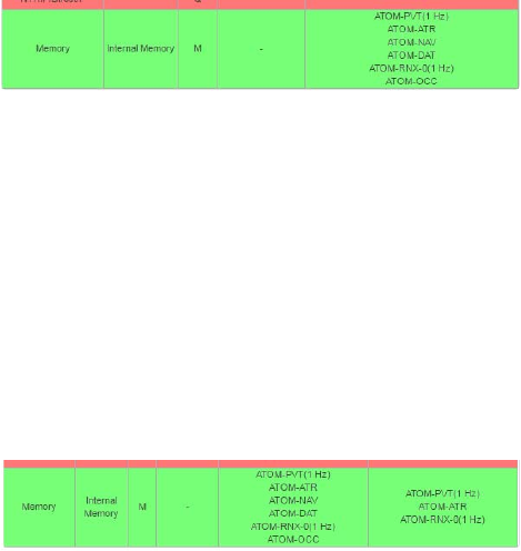
Raw Data
Recording
A default raw data output exists, which you should not modify
unless you have specific needs. This output is made available
on port M, which, at user’s choice, stands for either the
receiver’s internal memory or a USB device (USB key or hard
disk). Port M is the port used to save the collected raw data
as a G-file.
This output consists of the following ATOM messages:
• PVT: Positioning results
• ATR: Attributes (antenna parameters, receiver
description)
• NAV: Satellite navigation information
• DAT: Raw navigation data
• RNX-0: Receiver observations
• OCC: Site occupation information
G-files can be processed in SPSO (Spectra Precision Office
Software) or by the RINEX converter utility.
When two antennas are used, note that by default, only PVT,
ATR and RNX-0 are recorded for the secondary antenna.

78
Available NMEA
Messages
See details in Appendix.
Name Description
ALR Alarms
ARA True heading
ARR Vector & Accuracy
ATT True heading
AVR Time, yaw, tilt
BTS Bluetooth status
CAP Received base antenna
CPA Received antenna height
CPO Received base position
DDM Differential decoder message
DDS Differential decoder status
DTM Datum Reference
GBS GNSS Satellite Fault Detection
GGA GNSS position message
GGK GNSS position message
GGKX GNSS position message
GLL Geographic position - Latitude/Longitude
GMP GNSS Map Projection Fix Data
GNS GNSS Fix Data
GRS GNSS Range Residuals
GSA GNSS DOP and Active Satellites
GST GNSS Pseudo-range Error Statistics
GSV GNSS Satellites in View
HDT True heading
HPR True heading
LTN Latency
MDM Modem state and parameter
POS Position
PTT PPS time tag
PWR Power status
RCS Recording status
RMC Recommended Minimum Specific GNSS Data
SBD BEIDOU Satellites Status
SGA GALILEO Satellites Status (E1,E5a,E5b)
SGO GALILEO Satellites Status (E1,E5a,E5b,E6)
SGL GLONASS Satellites Status
SGP GPS Satellites Status
SIR IRNSS Satellites Status
SLB L-Band Satellites Status
SQZ QZSS Satellites Status
SSB SBAS Satellites Status
TEM Receiver temperature
THS True heading and status
TTT Event marker
VCR Vector and accuracy
VCT Vector and accuracy
VEL 3D velocity and velocity accuracy
VTG Course Over Ground and Ground Speed
ZDA Date and time

79
Appendices
Specifications GNSS Engine
• 480 GNSS tracking channels:
– GPS L1 C/A, L1P (Y), L2P (Y), L2C, L5, L1C
– GLONASS L1 C/A, L1P, L2 C/A, L2P, L3, L1/L2 CDMA
– GALILEO E1, E5a, E5b
– BeiDou B1, B2, B3 (1)
– QZSS L1 C/A, L1 SAIF, L1C, L2C, L5
–IRNSS L5
– SBAS L1 C/A, L5
• Two MSS L-band tracking channels
• Two GNSS antenna inputs
Features
• Patented Z-tracking to track encrypted GPS P(Y) signal
• Patented Strobe™ Correlator for reduced GNSS multi-
path
• Patented Z-Blade technology for optimal GNSS
performance:
– Highest quality of raw data (availability/reliability) to
meet reference station applications
– Full utilization of signals from all seven GNSS systems
(GPS, GLONASS, BeiDou, Galileo, QZSS, IRNSS, and
SBAS)
– Enhanced GNSS-centric algorithm: fully-independent
GNSS signal tracking and optimal data processing,
including GPS-only, GLONASS-only or BeiDou-only
solution (autonomous to full RTK) (2)
– Fast and stable RTK solution
– Fast Search engine for quick acquisition and re-
acquisition of GNSS signals
• Patented SBAS ranging for using SBAS code & carrier
observations and orbits in RTK processing
• Position in local datums and projections with RTCM-3
transformation data
• Support for Trimble RTX™ real-time correction services
• Trimble RTX™ PPP engine
• Hot Standby RTK Algorithms
• Flying RTK Algorithms
80
• RTK base and rovers modes, post-processing mode
• Moving base
– RTK with Static & Moving Base corrections supported
– Multi-dynamic mode (static/moving Base and Rover
functions simultaneously)
– RTK against a moving base for relative positioning
– Adaptive velocity filter to meet specific dynamic
applications
• Heading and Roll/Pitch
– Accurate and fast heading using dual-frequency,
multi-GNSS algorithms
– RTK or Trimble RTX and heading processing
simultaneously
– Heading engine with optional baseline length self-
calibration
– Adaptive velocity filter to meet specific dynamic
applications
• Up to 50 Hz real-time raw data (code & carrier and
position, velocity, and heading output) (3)
• Reference Inputs/Outputs: RTCM 3.2 (4), RTCM 3.1/3.0/
2.3/2.1, CMR/CMR+, CMRx (5), ATOM (6)
• Supported RTK networks: VRS, FKP, MAC
• NTRIP protocol
• Navigation outputs: NMEA-0183, ATOM
• PPS output
• Event marker input
• UHF networking
• One-push Ashtech Trouble Log (ATL)
GNSS Sensor Performance
• Time to First Fix (TTFF):
– Cold start: < 60 seconds
– Warm Start: < 45 seconds
– Hot Start: < 11 seconds
– Signal re-acquisition: < 2 seconds
• Position accuracy (HRMS), SBAS: < 50 cm (1.64 ft) (7)
• Update rate: Up to 50 Hz (3)
• Latency: < 10 ms (8)
• Velocity Accuracy: 0.02 m.sec HRMS
81
• Maximum Operating Limits (9)
– Velocity: 515 m/sec
– Altitude: 18,000 m
Precise Positioning Performance
Real-Time Accuracy (RMS) (10) (11)
• Real-Time DGPS Position:
– Horizontal: 25 cm (0.82 ft) + 1 ppm
– Vertical: 50 cm (1.64 ft) + 1 ppm
• Real-Time Kinematic Position (RTK):
– Horizontal: 8 mm (0.026 ft) + 1 ppm
– Vertical: 15 mm (0.049 ft) + 1 ppm
• Network RTK (12):
– Horizontal: 8 mm (0.026 ft) + 0.5 ppm
– Vertical: 15 mm (0.049 ft) + 0.5 ppm
Trimble RTX™ (Satellite and Cellular/Internet (IP)) (13) (14)
• CenterPoint® RTX
– Horizontal (HRMS): < 4 cm
– Initialization: < 30 min. (typical)
– Operating range (inland): Nearly worldwide
• CenterPoint RTX Fast
– Horizontal (HRMS): < 4 cm
– Initialization: < 5 min. (typical)
– Operating range (inland): In select regions
Heading (15) (16) (17)
• Accuracy (RMS): 0.2° per 1 m of baseline length
• Initialization time: < 10 sec typical
• Baseline length: < 100 m
Flying RTK
• 5 cm (0.165 ft) + 1 ppm (steady state) horizontal for
baselines up to 1000 km
82
Real-Time Performance
(10) (11)
• Instant-RTK® Initialization:
– Typically 2-second initialization for baselines < 20 km
– Up to 99.9% reliability
• RTK initialization range:
–> 40 km
Post-Processing Accuracy (RMS)
(10) (11)
Static, Rapid Static:
• Horizontal: 3 mm (0.009 ft) + 0.5 ppm
• Vertical: 5 mm (0.016 ft) + 0.5 ppm
High-Precision Static (18):
• Horizontal: 3 mm (0.009 ft) + 0.1 ppm
• Vertical: 3.5 mm (0.011 ft) + 0.4 ppm
Post-Processed Kinematic:
• Horizontal: 8 mm (0.026 ft) + 0.5 ppm
• Vertical: 20 mm (0.065 ft) + 1.0 ppm
Data Logging Characteristics
• Recording Interval: 0.02 (19)-999 seconds
Memory
• 8 GB internal memory
• Memory is expandable through external USB sticks or
hard drives
• Over four years of 15 sec. raw GNSS Data from 14
satellites (logged to internal 8GB Nand Flash)
Embedded Web Server
• Password-protected Web Server
• Full receiver monitoring and configuration
• FTP push function
• Embedded FTP server and NTRIP caster (20)
• NTRIP Server and instant real-time multi-data streaming
over Ethernet
• DHCP or manual configuration (static IP address)
• DynDNS® technology support
83
User and I/O Interface
• User Interface:
– Graphical OLED display with 6 keys and 1 LED
– WEB UI (accessible via WiFi or Ethernet) for easy
configuration, operation, status and data transfer
• I/O interface:
–1 x USB OTG
– Bluetooth v4.0 + EDR/LE, Bluetooth v2.1 + EDR
– WiFi (802.11 b/g/n)
– 3.5G quad-band GSM (850/900/1800/1900 MHz) /
penta-band UMTS module (800/850/900/1900/2100
MHz)
– 1 x Ethernet, RJ45 (Full-Duplex, auto-negotiate 10
Base-TX / 100 Base-TX)
– 1 x Lemo, RS232 (radio connection and external
power)
– 1 x DB9, RS232 (PPS output and CAN bus)
– 1 x DB9, RS422/232 (Event marker input)
– 2 x TNC, GNSS antenna input
– 1 x TNC, UHF radio antenna connector
– 1 x SMA, GSM antenna connector
– 1 x SMA, Bluetooth/WiFi antenna
–PPS output
– Event marker input
– Galvanic Insulation (Except USB)
– Ready for CAN bus (NMEA 2000 compatible)
Physical and Electrical Characteristics
• Size: 16.5 x 20.6 x 6.5 cm (6.5 x 8.1 x 2.6 in)
• Weight: GNSS receiver: 1.66 kg (3.66 lb) without UHF /
1.70 kg (3.75 lb) with UHF
• Battery life:
– 4 hrs (RTK Base, GNSS On, UHF Tx On), 12.8 W
average power consumption
– 6 hrs (RTK Rover, GNSS On, UHF Rx On), 5.9 W
average power consumption
• Li-ion battery, 27.8 Wh (7.4 V x 3.7 Ah). Acts as a UPS in
case of a power source outage
• 9-36 V DC input (EN2282, ISO7637-2)
• External DC power limits feature
84
Environmental Characteristics
• Operating temperature (21): -40° to +65°C (22) (-40° to
+149°F)
• Storage temperature (23): -40° to +95°C (-40° to +203°F)
• Humidity: Damp Heat 100% humidity, + 40°C (+104°F);
IEC 60945:2002
• IP67 (waterproof and dustproof): IEC 60529
• Drop: 1m drop on concrete
• Shock: MIL STD 810F (fig. 516.5-10) (01/2000).
Sawtooth (40g / 11ms)
• Vibrations: MIL-STD 810F (fig. 514.5C-17) (01/2000)
(1) Product is designed to fully support BeiDou B3 signals as soon as the
officially published signal Interface Control Documentation (ICD) becomes
available.
(2) All available GNSS signals are processed equally and combined without
preference to any particular constellation for optimal performance in harsh
environment.
(3) 50 Hz output is available as firmware option (20 Hz output is a standard
feature). At 50 Hz, a limited set of messages can be generated simultaneously
through a single port.
(4) RTCM-3.2 Multiple Signal Messaging (MSM) guarantees compatibility with
3rd party for each GNSS data.
(5) A Trimble proprietary format.
(6) ATOM: Open Ashtech format.
(7) VRMS for Autonomous/SBAS positions are usually twice as high as HRMS.
(8) Heading latency is usually twice as high.
(9) As required by the U.S. Department of Commerce to comply with export
licensing restrictions.
(10) Accuracy and TTFF specifications may be affected by atmospheric
conditions, signal multipath and satellite geometry.
(11) Performance values assume minimum of five satellites, following the
procedures recommended in the user guide. High multipath areas, high
PDOP values and periods of severe atmospheric conditions may degrade
performance.
(12) Network RTK PPM values are referenced to the closest physical base
station.
(13) Requires L1/L2 GPS+GLONASS at a minimum.
(14) Accuracy and TTFF specifications may be affected by atmospheric
conditions, signal multipath, satellite geometry and L-band service
availability. Trimble RTX correction services are only available on land.
(15) Accuracy and TTFF specifications may be affected by atmospheric
conditions, signal multipath, satellite geometry and corrections availability
and quality
(16) L1/L2 data required.
(17) Figures of pitch accuracy are twice as high.
(18) Depending on baselines, precise ephemeris and long occupations up to
24 hrs may be required to achieve the high precision static specifications.
85
(19) A Recording Interval of 0.05 is based on a 20 Hz output. The default
changes to 0.02 if the optional 50 Hz output firmware option is installed.
(20) Embedded NTRIP Caster is available as firmware option.
(21) Depends on whether the internal battery is used or not:
- With internal battery being charged: +45°C (+113°F) max.
- With internal battery being discharged: +60°C (+140°F)
- Without internal battery (external power supply): +65°C (+149°F)
under conditions of installation.
At very high temperature, the UHF module should not be used in transmitter
mode. With the UHF transmitter on radiating 2W of RF power, the operating
temperature is limited to +55°C (+131°F).
(22) At this temperature, hand protection may be needed to safely handle the
system’s lower aluminum housing (as per EN60945).
(23) Without battery. Battery can be stored up to +70°C (+158°F).
NOTE: All performance values are given assuming a minimum of five
satellites are used, and following the procedures recommended in the
user guide. High multipath areas, high PDOP values and periods of severe
atmospheric conditions may degrade performance.
86
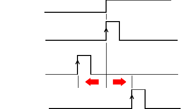
1PPS Output This output delivers a periodic signal that is a multiple or
submultiple of 1 second of GPS time, with or without offset.
Using the 1PPS output is a standard feature of the receiver
(no firmware option needed).
The 1PPS output is available on port F, pin 9.
You can set the properties of the 1PPS signal using the
$PASHS,PPS command. These properties are:
• Period: a multiple (1 to 60) or submultiple (0.1 to 1 in
0.1-second increments) of 1 second of GPS time.
• Offset: Amount of time in seconds before (+) or after (-) a
full second of GPS time.
• Active edge, i.e. the edge (falling or rising) synchronized
with GPS time. (On the diagram above, the rising edge is
set to be the active edge)
You can read the current properties of the 1PPS output using
the $PASHR,PPS command.
The signal specifications for the 1PPS output are as follows:
• Signal level: 0-5 V
• Pulse duration: 1 ms
• Jitter: < 100 ns
• Slope transient time: < 20 ns
You can also output the exact GPS time of the active edge of
the 1PPS output signal using the $PASHR,PTT command.
The receiver will respond to this command right after the next
1PPS signal is issued, taking into account the chosen offset.
1PPS with
Offset= 0
GPS time
1PPS with
Offset= - x.x sec
1PPS with
Offset= + x.x sec
+_

87
Event Marker Input This input is used to time-tag external events. When an
external event is detected on this input, the corresponding
GPS time for this event is output as a $PASHR,TTT message
on any port. The time tag provided in the message represents
the exact GPS time of the event to within 1 μsecond. A single
message is output for each new event.
Using the event marker input is a standard feature of the
receiver (no firmware option needed).
The event marker input is located on port B, pin 7.
You can choose whether it will be the rising or falling edge of
the event marker signal that will trigger the time tagging of
the event. This choice can be done using the $PASHS,PHE
command.
The signal specifications of the event marker input are as
follows:
• Signal level: ± 10 V
• Permitted transient time on active edge: < 20 ns
Resetting the
Receiver
With the SP90m turned off, press the two horizontal arrow
keys (right and left) AND the Power button simultaneously for
a few seconds until the power LED turns green.
This starts the receiver. The screen first displays the logo,
then Reset mode is displayed for a while. At the end of this
sequence, all receiver factory settings are restored.
The following parameters, functions and devices are not
impacted by the reset sequence:
• Last ephemeris data saved in the receiver (except for
SBAS data)
• Last almanac data saved in the receiver
• Last position and time computed by the receiver
• Anti-theft status and parameters
• Startup protection status and parameters
• Ethernet device power status (will remain ON if it was ON
before, or OFF if it was OFF) as opposed to all other
devices (WiFi, Modem, Bluetooth)
• All settings (PIN code, APN, login, password, etc.)
relevant to modem, Bluetooth, WiFi, Ethernet, Web Server
• SMS phone list, email address list and settings
• Automatic power-on and power-off settings
• Receiver validity period.
88
Upgrading the
Receiver Firmware
This can be done in different ways:
• Using the Web Server. Go to Receiver > Configuration >
Firmware Upgrade.
• USB key + OLED display (see page 37).
• USB key + key combination at receiver startup (see
page 44).
•Using the SP Loader software utility (see below).
SP Loader
Software Utility
Use Spectra Precision SP Loader software to:
1. Upgrade the receiver firmware
2. Install new firmware options based on the use of a POPN
delivered to you following the purchase of one of these
options.
3. Validate CenterPoint RTX subscription.
4. Read the warranty expiration date of a GNSS receiver.
Installing SP Loader
SP Loader can be downloaded from:
http://www.spectraprecision.com/eng/sp90m.html#.WUjSUdxLdhE
(Click on the Support tab to access the download link.)
The install file is an executable file. Simply double-click on
this file to start installation. Follow the instructions on the
screen to complete the installation.
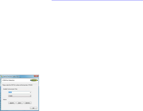
Getting Started With SP Loader
SP Loader will use either a serial (RS232), Bluetooth or USB
connection to communicate with the receiver. USB is
recommended.
1. Connect your computer to the SP90m using a USB
connection.
2. Run SP Loader on your computer.
3. Select the computer’s port ID used to communicate with
the receiver. This port ID should correspond to the
computer’s USB port.
NOTE: An easy way to identify which port ID on your
computer is the USB port is to run SP Loader first without
the USB connection and read the list of available ports in
SP Loader. After restoring the USB connection with the
receiver, check that list again. An extra port ID will then
be listed, being the one assigned to the USB port. Select
that port. (You don’t need to define a baud rate for a USB
port.)

89
4. To upgrade receiver firmware, install a new firmware
option or validate a CenterPoint RTX subscription, see
sub-sections below.
Upgrading Receiver Firmware
You are not allowed to
upgrade a receiver if anti-
theft or/and start up
protection is active or if the
receiver is operated with an
in-progress or expired
validity period.
Firmware upgrades will be downloadable from the Spectra
Precision website in the form of compressed “.tar” files. The
name of the “.tar” file, as well as the step-by step upgrade
procedure will be given in the accompanying Release Note.
Completing a firmware upgrade procedure will take up to
10 minutes. For this reason, it must be run with the receiver
powered from either a properly charged internal battery or
using an external power source.
Unless otherwise specified in the Release Note attached to
the upgrade package, follow the instructions below to
complete the upgrade of your receiver:
1. Follow the first three steps described in Getting Started
With SP Loader on page 88.
2. Click Upgrade. Wait until SP Loader has detected the
receiver.
3. Browse your computer in search of the upgrade file.
4. Select the file and click Open. SP Loader then provides
information on the currently installed firmware, the new
firmware as well as the current state of the battery (if the
internal battery is used).
This should tell you if you can run the upgrade with the
battery, or rather use a fresh one or an external power
supply.
5. When you are ready, click on the Update button.
6. Let the receiver proceed with the upgrade (a status
window is displayed showing a progress bar). Ensure the
receiver is not turned off while installation is in progress.
7. After successful completion of the upgrade, click Close to
close the status window. Check that the new firmware is
90
now installed (version and date displayed in the SP Loader
main window).
8. Click Close again, then Exit to quit SP Loader.
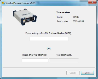
Installing a Firmware Option
Before you start this procedure, make sure you have received
an email from Spectra Precision containing the POPN (Proof
Of Purchase Number) corresponding to the firmware option
you have purchased.
NOTE : Your computer needs an Internet connection to install
a firmware option using a POPN.
With the POPN now in your possession, do the following to
install a new firmware option:
• Follow the first three steps described in Getting Started
With SP Loader on page 88.
• Click Option. Wait until SP Loader has detected the
receiver.
SP Loader then displays the serial number of your receiver
and prompts you to enter the POPN.
(There is an alternate method to activate a firmware
option, which is to enter the option key (provided by
Spectra Precision) corresponding to the desired firmware
option, and to specify that option in the nearby field.)
• Enter the POPN and then click on Update. Let the receiver
proceed with the installation of the firmware option (a
status window is displayed showing a progress bar).
Ensure the receiver is not turned off while installation is
in progress.
• After successful completion of the installation, click Close
to close the status window.
• Click Close again, then Exit to quit SP Loader.
91
Activating a CenterPoint RTX Subscription
After you have purchased a CenterPoint RTX subscription,
Trimble Positioning Services will email you an activation
code.
Use the same procedure as the one used to install a firmware
option (see page 90; the available RTX subscriptions are
listed as firmware options). The only difference is that no
POPN is provided for this procedure. Just enter the code
provided by Trimble Positioning Services and specify the type
of subscription you purchased before you click Update.
Reading Receiver Warranty Expiration Date
SP Loader can be used to query the Spectra Precision
database for the warranty expiration date of your GNSS
receiver. (After a receiver warranty has expired, remember
receiver firmware upgrades are no longer free of charge.)
You don’t need to have your receiver connected to SP Loader
to read its warranty expiration date. Just enter its type and
serial number and SP Loader will return this information to
you, provided there is an active Internet connection on your
computer, and your receiver is known to the database.
•Run SP Loader on your computer.
• Click on Warranty
• Select the type of your receiver and enter its serial number
• Click on Compute. SP Loader returns the warranty
expiration date in a field underneath the Compute button.
Additionally, SP Loader generates a proprietary command
that you can run in your receiver if you want to be sure
your receiver has the correct warranty expiration date in
memory. Carefully write down this command
Use Terminal Window in Survey Pro, or GPS Utility > Send
Command in FAST Survey to apply this command to the
receiver.
NOTE: When upgrading the receiver firmware using a
computer with an Internet connection, be aware SP Loader
will at the same time automatically check the warranty
expiration date of your receiver. SP Loader will ask you if it
can update this date if it is found wrong.
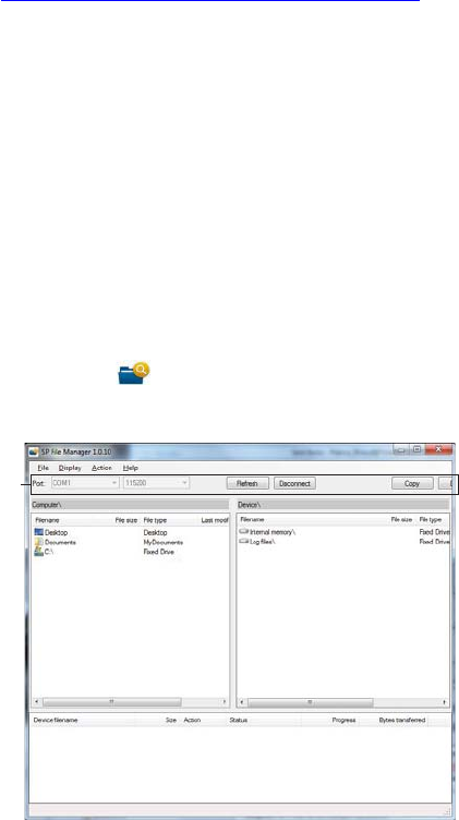
92
SP File Manager
Software Utility
SP File Manager allows you to copy “log” files and G-files
directly from the receiver’s internal memory to the desired
folder on your office computer.
Additionally you can delete any G-file or “log” file from the
receiver’s internal memory.
G-files are GNSS raw data files in proprietary format (ATOM).
“Log” files are editable text files listing all the operations
performed by the receiver in one day.
SP File Manager is available from the Spectra Precision
website as an executable file (SPFileManagerSetup.exe)
through the link below:
http://www.spectraprecision.com/eng/sp90m.html#.WUjSUdxLdhE
(Click on the Support tab to access the download link.)
Installing SP File Manager
SP File Manager is very easy to install:
• Download the executable file from the Spectra Precision
website (use above link).
• Double-click on the file to complete the installation.
Connecting SP90m to your Computer
SP File Manager will use either a serial (RS232), Bluetooth
or USB connection to communicate with the receiver. USB is
recommended.
Getting Started With SP File Manager
Double-click on . The SP File Manager window which
then appears is detailed below.
[2]
[1]
[3]
[4]

93
[1]: SP File Manager toolbar. This toolbar consists of the
following items:
•Port and baud rate scroll-down lists: Let you choose which
serial port is used on computer side for the connection
with the receiver (baud rate only makes sense when an
RS232 serial line is used). Use 115200 Bd to
communicate with SP90m.
•Connect / Refresh button: Connect allows you to activate
the connection between the computer and the receiver via
the chosen serial line.
When the connection is established, the button is
changed into Refresh, which allows you to update the
content of the two SP File Manager panes ([2] and [3]
described below)
•Disconnect button: Allows you to deactivate the connection
currently established between the computer and the
receiver.
•Copy button: Copies the file(s) selected in pane [3] to
pane [2]. In pane [2], you have to open the folder where
to copy to before clicking on the Copy button.
NOTE: Copied files have different creation dates and
times compared to those of their respective original files.
The new dates and times are those corresponding to when
the files were copied.
•Delete button: Deletes the files currently selected in pane
[2] or [3].
[2]: Pane showing the content of the currently open folder on
computer side.
[3]: Pane showing the content of the currently open folder on
receiver side. The receiver’s root folder contains two to three
sub-folders:
•Internal memory: Lists all G-files recorded by the receiver
in its internal memory
•Log files: Contains log files (one per day). Each log file
lists all the actions performed by the receiver in one day.
•USB key, if one is currently connected to the receiver.
To open a folder, double-click on it. To go back to the parent
folder, click on .
[4]: Pane showing copy/delete operations in progress, and all
those completed since the connection with the receiver was
established. This pane is cleared at the beginning of each
new working session of SP File Manager.

94
Establishing a Connection with the Receiver
• Set up the USB connection between the computer and
receiver.
• Turn on the receiver.
• Launch SP File Manager on your computer. This opens the
SP File Manager window.
• Select the right COM port (see also the Note in Getting
Started With SP Loader on page 88) and then click on the
Connect button.
As a result, the pane on the right-hand side of the window
lists the two or three folders that can be seen on the
receiver.
Copying Files to the Office Computer
• In the right-hand side of the window, double-click on the
sub-folder containing the files you want to copy to the
computer.
(If needed, click on to go back to the parent folder and
open another sub-folder.)
• In the left-hand side of the window, browse your computer
to the folder where to copy the files (recipient folder).
• In the right-hand side of the window, highlight the file(s)
you want to copy.
• Click on the Copy button. Files are then copied, as
requested. The lower part of the screen provides reports
information on the copy operations in progress.
Deleting Files from the Receiver
• In the right-hand side of the window, double-click on the
sub-folder containing the files you want to delete from the
receiver.
(If needed, click on to go back to the parent folder and
open another sub-folder.)
• Still in the right-hand side of the window, highlight the
file(s) you want to delete.
• Click on the Delete button. Files are then deleted. The
lower part of the screen provides reports information on
the delete operations in progress.
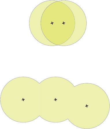
95
UHF Networking This feature allows a rover to receive corrections from up to
three different bases broadcasting separately their
corrections via radio, on the same frequency channel, but at
different times so the rover can receive these corrections
properly.
UHF networking can be implemented in SP90m provided you
use Survey Pro as the field software.
UHF networking may be used in two different modes:
• Manual: The rover operator chooses which of the bases to
work with. The bases will all be within range so the
operator can change the base used at all times (see
diagram below).
Typically, the manual mode is used when redundancy is
required in terms of corrections availability within a
working area. On the diagram below, the darker area
represents the area where the rover can operate from any
of the two bases.
• Automatic: The rover will automatically switch to the base
within range that provides the best quality of corrections.
Typically the automatic mode is used when you need to
extend the UHF radio coverage.
Implementing UHF networking on rover side consists of:
1. Activating this mode.
2. Choosing between automatic or manual selection of the
base used. In Survey Pro, this setting is accessible from
the GNSS Status function after you have started a survey.
Selecting the manual mode means specifying the ID of the
base you would like to work with.
Base 1 Base 2
Base 1 Base 2
Base 3

96
NMEA Messages ALR: Alarms
$PASHR,ALR,d1,d2,c3,s4,d5,s6*cc
ARA: True Heading
This message delivers either pitch- OR roll-related data
(speed, accuracy), not both at the same time, depending on
how the antennas are installed.
$PASHR,ARA,f1,m2,f3,f4,f5,f6,f7,f8,f9*cc
Parameter Description Range
d1 Alarm code 0-255
d2 Alarm sub-code 0-255
c3
Stream ID reporting the alarm (if
relevant, otherwise blank field):
• A, B, F: Serial port
• U: USB serial port
• C, H, T: Bluetooth port
• D: Internal radio
• E: CSD modem
• P, Q: TCP/IP client stream
• I, J: TCP/IP client server
• M: G-file
A-F, H-J, M, P, Q, U
s4 Alarm category
BLUETOOTH, INPUT, MEM-
ORY
MODEM, NETWORK, OTHER,
POWER, PVT, RADIO, WIFI
d5
Alarm level:
• 0: Low
• 1: Medium
•2: High
0-2
s6 Description
*cc Checksum *00-*FF
Parameter Description Range
f1 “0” when message content is valid
m2 Current UTC time of attitude fix
(hhmmss.ss) 000000.00-235959.99
f3 Heading speed, in degrees/sec “-”: Turn bow left
“+”: Turn bow right
f4 Pitch speed, in degrees/sec “-”: Downwards
“+”: Upwards
f5 Roll speed, in degrees/sec “-”: To port (left)
“+”: To starboard (right)
f6 Heading RMS accuracy, in degrees
f7 Pitch RMS accuracy, in degrees
f8 Roll RMS accuracy, in degrees
f9 (Empty)
*cc Checksum *00-*FF

97
ARR: Vector & Accuracy
$PASHR,ARR,d0,d1,d2,m3,f4,f5,f6,f7,f8,f9,f10,f11,f12,d13,d14,d15,d16*cc
Parameter Description Range
d0 Vector number 1, 2, 3
d1
Vector mode:
• 0: Invalid baseline
• 1: Differential
• 2: RTK float
• 3: RTK fixed
• 5: Other (dead reckoning, bad accuracy, difference
between standalone positions). Messages with
d1=5 may further be masked if users only want
proven vector estimates.
0-3, 5
d2 Number of SVs used in baseline computation (L1 por-
tion) 0-99
m3 UTC time (hhmmss.ss) 000000.00-
235959.99
f4 Delta antenna position, ECEF 1st coordinate (in
meters) ±99999.999
f5 Delta antenna position, ECEF 2nd coordinate (in
meters) ±99999.999
f6 Delta antenna position, ECEF 3rd coordinate (in
meters) ±9999.999
f7 1st coordinate of standard deviation 99.999
f8 2nd coordinate of standard deviation 99.999
f9 3rd coordinate of standard deviation 99.999
f10 1st/2nd coordinate correlation ±99.999999
f11 1st/3rd coordinate correlation ±99.999999
f12 2nd/3rd coordinate correlation ±99.999999
c13 Reference data ID 1, 2, port let-
ter
d14 Vector coordinate frame ID:
• 0: XYZ 0
d15
Vector operation:
• 0: Fixed mode (vector length is constrained)
• 1: Calibration (vector length is being calibrated)
• 2: Flex mode
0-2
d16
Clock assumption:
• 0: Clock is assumed to be different for the “head”
and “tail” of the vector (see Comments below)
• 1: Clock is assumed to be the same for the “head”
and “tail” of the vector (see Comments below)
*cc Checksum *00-*FF

98
ATT: True Heading
This message delivers either pitch OR roll angles, not both at
the same time, depending on how the antennas are installed.
$PASHR,ATT,f1,f2,f3,f4,f5,f6,d7*cc
AVR: Time, Yaw, Tilt
$PTNL,AVR,m1,f2,Yaw,f3,Tilt,,,f4,s5,f6,d7*cc
Parameter Description Range
f1 Week time in seconds. 000000.00-604799.99
f2 True heading angle in degrees. 000.00-359.99999
f3 Pitch angle in degrees. ±90.00000
f4 Roll angle in degrees. ±90.00000
f5 Carrier measurement RMS error, in
meters.
Full range of real vari-
ables
f6 Baseline RMS error, in meters. Full range of real vari-
ables
d7
Integer ambiguity is “Fixed” or “Float”:
•0: Fixed
• >0: Float
0, >0
*cc Checksum *00-*FF
Parameter Description Range
m1 Current UTC time of vector fix (hhmmss.ss) 000000.00-
235959.99
f2,Yaw Yaw angle, in degrees.
f3,Tilt Tilt angle, in degrees.
f4 Range, in meters
d5
GNSS quality indicator:
• 0: Fix not available or invalid
• 1: Autonomous GPS fix.
• 2: Differential carrier phase solution RTK (float)
• 3: Differential carrier phase solution RTK (fixed)
• 4: Differential code-based solution
0-4
f6 PDOP 0-9.9
d7 Number of satellites used in solution
*cc Checksum *00-*FF

99
BTS: Bluetooth Status
$PASHR,BTS,C,d1,s2,s3,d4,H,d5,s6,s7,d8,T,d9,s10,s11,d12*cc
CAP: Received Base Antenna
$PASHR,CAP,s1,f2,f3,f4,f5,f6,f7*cc
Parameter Description Range
C,d1
Port C:
• 0: Not connected
• 1: A device is connected
0, 1
s2 Device name connected to port C 64 char. max.
s3 Device address connected to port
C(xx:xx:xx:xx:xx:xx) 17 char.
d4 Bluetooth link quality for the port C connection 0-100
H,d5
Port H:
• 0: Not connected
• 1: A device is connected
0, 1
s6 Device name connected to port H 64 char. max.
s7 Device address connected to port H
(xx:xx:xx:xx:xx:xx) 17 char.
d8 Bluetooth link quality for the port H connection 0-100
T,d9
Port T:
• 0: Not connected
• 1: A device is connected
0, 1
s10 Device name connected to port T 64 char. max.
s11 Device address connected to port T
(xx:xx:xx:xx:xx:xx) 17 char.
d12 Bluetooth link quality for the port T connection 0-100
*cc Checksum *00-*FF
Parameter Description
s1 Antenna name, “NONE” if no name received for the base antenna.
f2 L1 North offset, in mm
f3 L1 East offset, in mm
f4 L1 Up offset, in mm
f5 L2 North offset, in mm
f6 L2 East offset, in mm
f7 L2 Up offset, in mm
*cc Checksum

100
CPA: Received Antenna Height
$PASHR,CPA,f1,f2,f3,m4,f5*cc
CPO: Received Base Position
$PASHR,CPO,m1,c2,m3,c4,f5*cc
DDM: Differential Decoder Message
$PASHR,DDM,c1,s2,s3,d4,s5,f6,f7,s8*cc
Parameter Description Range
f1 Antenna height, in meters. This field remains empty
as long as no antenna height has been received. 0-99.999
f2 Antenna radius, in meters 0-9.9999
f3 Vertical offset, in meters 0-99.999
m4 Horizontal azimuth, in degrees, minutes (dddmm.mm) 0-35959.99
f5 Horizontal distance, in meters 0-99.999
f2, f3, m4, f5 Not applicable, all empty fields -
*cc Checksum *00-*FF
Parameter Description Range
m1 Latitude in degrees and minutes with 7 deci-
mal places (ddmm.mmmmmmm) 0-90
c2 North (N) or South (S) N, S
m3 Longitude in degrees, minutes with 7 decimal
places (dddmm.mmmmmmm) 0-180
c4 West (W) or East (E) W, E
f5 Height in meters ±99999.999
*cc Checksum *00-*FF
Parameter Description Range
c1 Port receiving corrections A-E, I, P, Q, Z
s2 Message transport RT2, RT3, CMR, CMX or ATM
s3 Message number/identifier e.g. 1004 for RT3, RNX for ATM,
etc.
d4 Counter of decoded messages 0-9999
s5 Base ID
f6 Time tag, in seconds, as read
from the decoded message
f7 Age of corrections, in seconds
s8 Attribute 60 characters max.
*cc Checksum *00-*FF

101
DDS: Differential Decoder Status
$PASHR,DDS,d1,m2,d3,c4,s5,c6,d7,d8,d9,d10,d11,f12,f13,d14,n(d15,
f16,f17)*cc
Parameter Description Range
d1
Differential decoder number.
“1” corresponds to first decoder, etc.
An empty field means the decoder
used is not known.
1-4
m2 GNSS (output) time tag 000000.00-235959.99
d3 Number of decoded messages since
last stream change 0-127
c4 ID of port from which corrections are
received A-E, I, P, Q, Z
s5 Protocol detected (empty means “no
data”)
RT2, RT3, CMR, ATM,
CMX
d6
Time window, in seconds:
• “0” if not defined or just initialized
• “200” means equal to or greater
than 200
0-200
d7
Percentage of estimated overall data
link quality/availability. Empty if not
defined.
0-100
d8 Percentage of deselected informa-
tion. Empty if not defined. 0-100
d9 CRC percentage. Empty if not
defined. 0-100
d10 Standard of latency, in milliseconds 0-16383
d11 Mean latency, in milliseconds 0-16383
f12 Mean epoch interval, in seconds 0.00-3600
f13 Min. epoch interval, in seconds 0.00-3600
d14 Number (n) of different messages
detected since last stream change 0-63
d15 Message type
RT2: 1-63
RT3: 1001-4094
CMR: 0(obs), 1(loc),
2(desc), 3(glo), 12(cmr+),
20 (glo encrypted)
ATM: 0-15
CMX: no message reported
f16 Interval of last message, in seconds 0.000-1023.000
f17 Age of last message, in seconds 0.000-1023.000
*cc Checksum

102
DTM: Datum Reference
$GPDTM,s1,,f2,c3,f4,c5,f6,s7*cc
GBS: GNSS Satellite Fault Detection
$--GBS,m1,f2,f3,f4,d5,f6,f7,f8,h9,h10*cc
Parameter Description Range
s1
Local datum code:
• W84: WGS84 used as local datum
• 999: Local datum computed using the
parameters provided by the RTCM3.1
data stream.
W84, 999
f2 Latitude offset, in meters 0-59.999999
c3 Direction of latitude N, S
f4 Longitude offset, in meters 0-59.999999
c5 Direction of longitude E, W
f6 Altitude offset, in meters ±0-99.999
s7 Reference datum code W84
*cc Checksum *00-*FF
Parameter Description Range
m1 UTC time of the GGA or GNS fix asso-
ciated with this message (hhmmss.ss) 000000.00-235959.99
f2 Expected error in latitude, in meters,
due to bias, with noise= 0 0.0-99.9
f3 Expected error in longitude, in meters,
due to bias, with noise= 0 0.0-99.9
f4 Expected error in altitude, in meters,
due to bias, with noise= 0 0.0-99.9
d5 ID number of most likely failed satellite
1-32 for GPS
33-64 for SBAS
65-96 for GLONASS
97-128 for Galileo
129-160 for BeiDou
193-202 for QZSS
f6 Probability of missed detection for
most likely failed satellite 0.00-1.00
f7 Estimate of bias, in meters, on most
likely failed satellite 0.0-99.9
f8 Standard deviation of bias estimate 0.0-99.9
h9 GNSS system ID 0-F
h10 GNSS signal ID 0-F
*cc Checksum *00-*FF

103
GGA: GNSS Position Message
$GPGGA,m1,m2,c3,m4,c5,d6,d7,f8,f9,M,f10,M,f11,d12*cc
GGK: GNSS Position Message
See Trimble documentation.
Parameter Description Range
m1 Current UTC time of position (hhmmss.ss) 000000.00-
235959.99
m2 Latitude of position (ddmm.mmmmmm) 0-90
0-59.999999
c3 Direction of latitude N, S
m4 Longitude of position (dddmm.mmmmmm) 0-180
0-59.999999
c5 Direction of longitude E,W
d6
Position type:
• 0: Position not available or invalid
• 1: Autonomous position
• 2: RTCM Differential (or SBAS Differential)
•3: Not used
•4: RTK fixed
•5: RTK float
• 6: Estimated (dead reckoning) mode
0-6
d7 Number of GNSS Satellites being used in the
position computation 3-26
f8 HDOP 0-99.9
f9,M Altitude, in meters, above mean seal level.
“M” for meters ± 99999.999,M
f10,M Geoidal separation in meters. “M” for meters. ± 999.999,M
f11 Age of differential corrections, in seconds 0-600999
d12 Base station ID 0-4095
*cc Checksum *00-*FF

104
GGKX: GNSS Position Message
$PTNL,GGKx,m1,m2,m3,c4,m5,c6,d7,d8,f9,f10,M,d11,f12,f13,f14,f15*cc
Parameter Description Range
m1 Current UTC time of position (hhmmss.ss) 000000.00-
235959.99
m2 UTC date of position (mmddyy) 010101-123199
m3 Latitude of position (ddmm.mmmmmm) 0-90
0-59.999999
c4 Direction of latitude N, S
m5 Longitude of position (dddmm.mmmmmm) 0-180
0-59.999999
c6 Direction of longitude E,W
d7
Position type:
• 0: Position not available or invalid
• 1: Autonomous GPS fix
• 2: RTK float solution or RTK location status
• 3: RTK fix solution
• 4: Differential, code phase only solution
• 5: SBAS solution
• 6: 3D network solution for RTK float or RTK
location
• 7: RTK fixed 3D network solution
• 8: 2D network solution for RTK float or RTK
location
• 9: RTK fixed 2D network solution
• 10: OmniSTAR HP/XP solution
• 11: OmniSTAR VBS solution
• 12: RTK location
• 13: Beacon DGPS
• 14: RTK Global
0-14
d8 Number of GNSS Satellites being used in the
position computation 3-26
f9 PDOP 0-99.9
f10,M
Ellipsoid height of fix (antenna height above
ellipsoid.
“M” for meters.
± 99999.999,M
d11 Number of extension fields to follow.
f12 Sigma East 0.000-999.999
f13 Sigma North 0.000-999.999
f14 Sigma Up 0.000-999.999
f15 Propagation age
*cc Checksum *00-*FF

105
GLL: Geographic Position - Latitude/Longitude
$GPGLL,m1,c2,m3,c4,m5,c6,c7*cc
Parameter Description Range
m1 Latitude of position (ddmm.mmmmmm) 0-90
0-59.999999
c2 Direction of latitude N, S
m3 Longitude of position (dddmm.mmmmmm) 0-180
0-59.999999
c4 Direction of longitude E,W
m5 Current UTC time of position (hhmmss.ss) 000000.00-
235959.99
c6
Status
• A: Data valid
• V: Data not valid
A, V
c7
Mode indicator:
• A: Autonomous mode
• D: Differential mode
• N: Data not valid
• E: Estimated (dead reckoning) mode
A, D, N, E
*cc Checksum *00-*FF

106
GMP: GNSS Map Projection Fix Data
$--GMP,m1,s2,s3,f4,f5,s6,d7,f8,f9,f10,f11,d12*cc
Parameter Description Range
“$--GMP”
Header
$GPGMP: Only GPS satellites are used.
$GLGMP: Only GLONASS satellites are used.
$GNGMP: Several constellations (GPS,
SBAS, GLONASS) are used.
$GPGMP,
$GLGMP,
$GNGMP
m1 Current UTC time of position (hhmmss.ss) 000000.00-
235959.99
s2
Map projection identification:
• LOC: Local coordinate system
• Empty if no local coordinate system
LOC
s3 Map zone
(empty)
f4 X (Northern) component of grid (or local) coor-
dinate, in meters ±999999999.999
f5 Y (Eastern) component of grid (or local) coor-
dinate, in meters ±999999999.999
s6
Mode indicator:
• N: No fix
• A: Autonomous
• D: Differential
•R: Fixed RTK
• F: Float RTK
N, A, D, R, F
d7 Number of GNSS Satellites being used in the
position computation 3-26
f8 HDOP 0-99.9
f9 Altitude above mean seal level, or local alti-
tude, in meters. ± 99999.999,M
f10 Geoidal separation in meters. ± 999.999,M
f11 Age of differential corrections, in seconds 0-999.9
d12 Base station ID 0-4095
*cc Checksum *00-*FF

107
GNS: GNSS Fix Data
$--GNS,m1,m2,c3,m4,c5,s6,d7,f8,f9,f10,f11,d12*cc
Parameter Description Range
m1 Current UTC time of position
(hhmmss.ss) 000000.00-235959.99
m2 Latitude of position
(ddmm.mmmmmm)
0-90
0-59.999999
c3 Direction of latitude N, S
m4 Longitude of position
(dddmm.mmmmmm)
0-180
0-59.999999
c5 Direction of longitude E, W
s6
Mode indicator (1 character by con-
stellation):
• N: No fix
• A: Autonomous position
• D: Differential
•R: RTK Fixed
•F: RTK Float
N, A, D, R, F
d7 Number of GNSS satellites being
used in the position computation. 3-26
f8 HDOP 0-99.9
f9 Altitude above mean sea level. ±99999.999
f10 Geoidal separation, in meters ±999.999
f11 Age of differential corrections, in s 0-999
d12 Base station ID (RTCM only) 0-4095
*cc Checksum

108
GRS: GNSS Range Residuals
$--GRS,m1,d2,n(f3)*cc
GSA: GNSS DOP and Active Satellites
$--GSA,c1,d2,d3,d4,d5,d6,d7,d8,d9,d10,d11,d12,d13,d14,f15,f16,f17*cc
Parameter Description Range
“$--GRS”
Header
$GPGRS: Only GPS satellites are used.
$GLGRS: Only GLONASS satellites are used.
$GNGRS: Several constellations (GPS, SBAS,
GLONASS) are used.
$GBGRS: Only BeiDou satellites are used.
$GNGRS: Several constellations are used (GPS,
SBAS, GLONASS, QZSS, BeiDou)
$GPGRS
$GLGRS
$GBGRS
$GNGRS
m1 Current UTC time of GGA position (hhmmss.ss) 000000.00-
235959.99
d2 Mode used to compute range residuals Always “1”
f3
Range residual for satellite used in position computa-
tion (repeated “n” times, where n is the number of sat-
ellites used in position computation). Residuals are
listed in the same order as the satellites in the GSA
message so that each residual provided can easily be
associated with the right satellite.
±999.999
*cc Checksum *00-*FF
Parameter Description Range
“$--GSA”
Header
$GPGSA: Only GPS satellites are used.
$GLGSA: Only GLONASS sats are used.
$GBGSA: Only BEIDOU sats are used
$GNGSA: Several constellations (GPS,
SBAS, GLONASS, BEIDOU) are used.
$GPGSA, $GLGSA,
$GBGSA, $GNGSA
c1
Output mode:
• M: Manual
• A: Automatic
M, A
d2
Position indicator:
• 1: No position available
• 2: 2D position
• 3: 3D position
1-3
d3-d14 Satellites used in the position solution
(blank fields for unused channels)
GPS: 1-32
GLONASS: 65-96
SBAS: 1-44
GALILEO: 1-30
QZSS: 1-5
BEIDOU: 1-35
IRNSS: 1-7
f15 PDOP 0-9.9
f16 HDOP 0-9.9
f17 VDOP 0-9.9
*cc Checksum *00-*FF

109
GST: GNSS Pseudo-range Error Statistics
$--GST,m1,f2,f3,f4,f5,f6,f7,f8*cc
GSV: GNSS Satellites in View
$--GSV,d1,d2,d3,n(d4,d5,d6,f7),h8*cc
Parameter Description Range
“$--GST”
Header
$GPGST: Only GPS satellites are used.
$GLGST: Only GLONASS satellites are used.
$GNGST: Several constellations (GPS, SBAS,
GLONASS, BEIDOU) are used.
$GPGST,
$GLGST,
$GNGST
m1 Current UTC time of position (hhmmss.ss) 000000.00-
235959.99
f2 RMS value of standard deviation of range inputs
(DGNSS corrections included), in meters 0.000-999.999
f3 Standard deviation of semi-major axis of error
ellipse, in meters 0.000-999.999
f4 Standard deviation of semi-minor axis of error
ellipse, in meters 0.000-999.999
f5 Orientation of semi-major axis of error ellipse, in
degrees from true North 0 to 180
f6 Standard deviation of latitude error, in meters 0.000-999.999
f7 Standard deviation of longitude error, in meters 0.000-999.999
f8 Standard deviation of altitude error, in meters 0.000-999.999
*cc Checksum *00-*FF
Parameter Description Range
“$--GSV”
Header
$GPGSV: GPS satellites.
$GLGSV: GLONASS satellites
$GAGSV: GALILEO satellites
$GSGSV: SBAS satellites (including
QZSS L1 SAIF)
$GQGSV: QZSS satellites
$GBGSV: BeiDou satellites
$GIGSV: IRNSS satellites
$GPGSV,
$GLGSV
$GAGSV
$GSGSV
$GQGSV
$GBGSV
$GIGSV
d1 Total number of messages 1-4
d2 Message number 1-4
d3 Total number of satellites in view 0-16
d4 Satellite PRN
GPS: 1-32
GLONASS: 65-96
SBAS: 1-44
GALILEO: 1-30
QZSS: 1-5
BEIDOU: 1-35
IRNSS: 1-7
d5 Elevation in degrees 0-90
d6 Azimuth in degrees 0-359
f7 SNR in dB.Hz 30.0-60.0
h8 Signal ID 0-F
*cc Checksum *00-*FF

110
HDT: True Heading
$GPHDT,f1,T*cc
HPR: True Heading
This message delivers either pitch OR roll angles, not both at
the same time, depending on how the antennas are installed.
$PASHR,HPR,m1,f2,f3,f4,f5,f6,d7,d8,d9,f10*cc
Parameter Description Range
f1,T Last computed heading value, in degrees
“T” for “True”. 0-359.99
*cc Checksum *00-*FF
Parameter Description Range
m1 UTC time of attitude data (hhmmss.ss). 000000.00-
235959.99
f2 True heading angle in degrees. 000.00-359.99999
f3 Pitch angle in degrees. ±90.00000
f4 Roll angle in degrees. ±90.00000
f5 Carrier measurement RMS error, in meters. Full range of real
variables
f6 Baseline RMS error, in meters.
(=0 if baseline is not constrained)
Full range of real
variables
d7
Integer ambiguity:
•0: Fixed
• >0: Float
0, >0
d8
Attitude/heading mode status:
• 0: Operation with fixed baseline length
• 1: Calibration in progress
• 2: Flex (flexible) baseline mode ON
0, 1, 2
d9
Character string of the type “y.xxx” defined
as follows:
• “y” refers to the antenna setup:
y=0: no length constraint is applied
y=1: heading mode (one vector)
y=2: attitude mode (2 vectors)
y=3: attitude mode with 3 or more vectors
• Each “x” (0 to 9) represents the number of
Double Differences (DD) used in the corre-
sponding baseline.
If this number is greater than 9, then “9” is
reported.
If there are only 2 vectors, the last x is “0”
Double differences refer to the very last inte-
ger second time-tagged epoch.
y.xxx
f10
PDOP corresponding to vector V12, as com-
puted for the very last integer second (time-
tagged epoch). Empty if PDOP unknown.
*cc Checksum *00-*FF

111
LTN: Latency
$PASHR,LTN,d1*cc
MDM: Modem State and Parameter
$PASHR,MDM,c1,d2,s3,PWR=s4,PIN=s5,PTC=d6,CBS=d7,APN=s8,LGN=s
9,PWD=s10,PHN=s11,ADL=c12,RNO=d13,MOD=s14,NET=d15,ANT=s16*cc
Parameter Description Range
d1 Latency in milliseconds.
*cc Optional checksum *00-*FF
Parameter Description Range
c1 Modem port E
d2 Modem baud rate 9
s3
Modem state.
“NONE” means that MODEM option
[Z] is not valid.
OFF, ON, INIT, DIALING,
ONLINE, NONE
PWR=s4
Power mode:
• AUT: Automatic
• MAN: Manual
AUT, MAN
PIN=s5 PIN code 4-8 digits
PTC=d6
Protocol:
•0: CSD
•1: GPRS
0-1
CBS=d7
Not used
CSD mode:
• 0: V.32 9600 bauds
• 1: V.110 9600 bauds ISDN
0-1
APN=s8 Access Point Name (GPRS) 32 char. max.
LGN=s9 Login (GPRS) 32 char. max.
PWD=s10 Password (GPRS) 32 char. max.
PHN=s11 Phone number (CSD) 20 digits max.
ADL=c12 Auto-dial mode Y, N
RNO=d13 Maximum number of re-dials (CSD) 0-15
MOD=s14 Modem model (empty if unknown) Centurion PHS8
NET=d15
2G/3G selection mode:
• 0: Automatic (2G or 3G)
• Forced to operate in 2G
0-1
ANT=S16
GSM antenna used:
• INT: Internal
• EXT: External
INT, EXT
*cc Checksum *00-*FF

112
POS: Position
$PASHR,POS,d1,d2,m3,m4,c5,m6,c7,f8,f9,f10,f11,f12,f13,f14,f15,f16,d17*cc
Parameter Description Range
d1
Flag describing position solution type:
• 0: Autonomous position
• 1: RTCM code differential (or SBAS/BDS differ-
ential)
• 2: RTK float (or RTX)
• 3: RTK fixed (or RTX)
• 5: Estimated (dead-reckoning) mode
• 9: SBAS differential
• 10: BeiDou Differential
• 12: RTK float
• 13: RTK fixed
• 22: RTK Float Dithered
• 23: RTK Fixed, Dithered
0-3, 5, 9-10,
12-13, 22-23
d2 Count of satellites used in position computation 0-26
m3 Current UTC time of position (hhmmss.ss) 000000.00-
235959.99
m4 Latitude of position (ddmm.mmmmmm)
0-90°
00-59.999999
minutes
c5 North (N) or South (S) N, S
m6 Longitude of position (dddmm.mmmmmm)
0-180°
00--59.999999
minutes
c7 East (E) or West (W) E, W
f8 Altitude above the WGS84 ellipsoid ±9999.000
f9 Age of differential corrections (seconds) 0-999.9
f10 True Track/Course Over Ground, in degrees 0.0-359.9
f11 Speed Over Ground, in knots 0.0-999.999
f12 Vertical velocity in m/s ±999.999
f13 PDOP 0-99.9
f14 HDOP 0-99.9
f15 VDOP 0-99.9
f16 TDOP 0-99.9
d17 Base station ID 0-4095
*cc Checksum *00-*FF

113
PTT: PPS Time Tag
$PASHR,PTT,d1,m2*cc
PWR: Power Status
$PASHR,PWR,d1,[f2],[f3],[d4],[d5],[f6],[d7],[d8],d9[,d10]*cc
Parameter Description Range
d1
Day of week:
• 1: Sunday
• 7: Saturday
1-7
m2 GPS time tag in hours, minutes, seconds 0-23:59:59.9999999
*cc Checksum *00-*FF
Parameter Description Range
d1
Power source:
• 0: Internal battery
• 1: External battery
• 2: External DC source
0-2
f2 Output voltage of battery (internal), in volts 0.0-12.0
f3 Empty
d4 Percentage of remaining battery energy 0-100
d5 Empty
f6 DC input voltage from external power, in volts 0.0-30.0
d7
Battery charging status:
• 0: Charging
• 1: Discharging
• 2: Fully charged
• 3: Fully discharged
0-3
d8 Empty
d9 Internal temperature, in degrees C
d10 Battery temperature, in degrees C
*cc Checksum *00-*FF

114
RCS: Recording Status
??????????????????????????
$PASHR,RCS,c1,d2,s3,d4,f5,f6,f7,d8,d9)*cc
Parameter Description Range
c1
Recording status:
• Y: Data recording in progress; receiver will keep
on recording data after a power cycle.
• N: No data recording in progress; after a power
cycle, no recording will start either.
• S: No data recording in progress, but receiver
will start recording data after a power cycle.
• R: Data recording in progress, but receiver will
stop recording data after a power cycle.
Y, N, S, R
d2 Memory where data file is recorded:
• 0: Internal memory
s3 Data filename 255 char. max.
d4 Recording rate, in seconds: 0.05-960
f5
Occupation type:
•0: Static
• 1: Quasi-static
• 2: Dynamic
0-2
d6
Occupation state:
• 0: In progress
• 1: No occupation
0-1
s7 Occupation name 255 char. max.
*cc Checksum *00-*FF

115
RMC: Recommended Minimum Specific GNSS Data
$GPRMC,m1,c2,m3,c4,m5,c6,f7,f8,d9,f10,c11,c12*cc
SBD: BEIDOU Satellites Status
$PASHR,SBD,d1,n(d2,d3,d4,f5,f6,f7,c8,c9)*cc
Parameter Description Range
m1 Current UTC time of position (hhmmss.ss) 000000.00-
235959.99
c2
Status
• A: Data valid
•V:
A, V
m3 Latitude of position (ddmm.mmmmmm) 0-90
0-59.999999
c4 Direction of latitude N, S
m5 Longitude of position (dddmm.mmmmmm) 0-180
0-59.999999
c6 Direction of longitude E,W
f7 Speed Over Ground, in knots 000.0-999.9
f8 Course Over Ground, in degrees (true) 000.0-359.9
d9 Date (ddmmyy) 010100-311299
f10 Magnetic variation, in degrees 0.00-99.9
c11 Direction of variation E, W
c12
Mode indicator:
• A: Autonomous mode
• D: Differential mode
• N: Data not valid
A, D, N
*cc Checksum *00-*FF
Parameter Description Range
d1 Number of visible satellites 0-37
d2 Satellite PRN number 1-37
d3 Satellite azimuth, in degrees 0-359
d4 Satellite elevation, in degrees 0-90
f5 Satellite B1 signal/noise in dB.Hz 0.0-60.0
f6 Satellite B2 signal/noise in dB.Hz 0.0-60.0
f7 Satellite B3 signal/noise in dB.Hz 0.0-60.0
c8 Satellite usage status
c9 Satellite correcting status
*cc Checksum *00-*FF

116
SGA: GALILEO Satellites Status (E1,E5a,E5b)
$PASHR,SGA,d1,n(d2,d3,d4,f5,,f7,c8,c9)*cc
SGL: GLONASS Satellites Status
$PASHR,SGL,d1,n(d2,d3,d4,f5,f6,f7,c8,c9)*cc
SGO: GALILEO Satellites Status (E1,E5a,E5b,E6)
$PASHR,SGO,d1,n(d2,d3,d4,f5,f6,f7,f8,f9,c10,c11)*cc
Parameter Description Range
d1 Number of visible satellites 0-36
d2 SV PRN number 1-36
d3 SV azimuth in degrees 0-359
d4 SV elevation angle in degrees 0-90
f5 SV E1 signal/noise in dB.Hz 0.0-60.0
f6 SV E5b signal/noise in dB.Hz 0.0-60.0
f7 SV E5a signal/noise in dB.Hz 0.0-60.0
c8 Satellite usage status
c9 Satellite correcting status
*cc Checksum *00-*FF
Parameter Description Range
d1 Number of visible satellites 0-24
d2 SV PRN number 1-24
d3 SV azimuth in degrees 0-359
d4 SV elevation angle in degrees 0-90
f5 SV L1 signal/noise in dB.Hz 0.0-60.0
f6 SV L2 signal/noise in dB.Hz 0.0-60.0
f7 SV L3 signal/noise in dB.Hz 0.0-60.0
c8 Satellite usage status
c9 Satellite correcting status
*cc Checksum *00-*FF
Parameter Description Range
d1 Number of visible satellites 0-36
d2 SV PRN number 1-36
d3 SV azimuth in degrees 0-359
d4 SV elevation angle in degrees 0-90
f5 SV E1 signal/noise in dB.Hz 0.0-60.0
f6 SV E5b signal/noise in dB.Hz 0.0-60.0
f7 SV E5a signal/noise in dB.Hz 0.0-60.0
f8 SV E6 signal/noise in dB.Hz 0.0-60.0
f9 Empty
c10 Satellite usage status
c11 Satellite correcting status
*cc Checksum *00-*FF

117
SGP: GPS Satellites Status
$PASHR,SGP,d1,n(d2,d3,d4,f5,f6,f7,c8,c9)*cc
SIR: IRNSS Satellites Status
$PASHR,SIR,d1,n(d2,d3,d4,f5,f6,f7,c8,c9)*cc
SLB: L-Band Satellites Status
$PASHR,SLB,d1,n(d2,d3,d4,d5,f6)*cc
Parameter Description Range
d1 Number of visible satellites 0-63
d2 SV PRN number 1-63
d3 SV azimuth in degrees 0-359
d4 SV elevation angle in degrees 0-90
f5 SV L1 signal/noise in dB.Hz 0.0-60.0
f6 SV L2 signal/noise in dB.Hz 0.0-60.0
f7 SV L5 signal/noise in dB.Hz 0.0-60.0
c8 Satellite usage status
c9 Satellite correcting status below)
*cc Checksum *00-*FF
Parameter Description Range
d1 Number of visible satellites 0-7
d2 SV PRN number 1-7
d3 SV azimuth in degrees 0-359
d4 SV elevation angle in degrees 0-90
f5 Empty
f6 Empty
f7 SV L5 signal/noise in dB.Hz 0.0-60.0
c8 Satellite usage status
c9 Satellite correcting status below)
*cc Checksum *00-*FF
Parameter Description Range
d1 Number of visible satellites 0-11
d2 L-Band satellite number 01-07, 08-11
d3 Continuous tracking interval, in seconds
d4 SV azimuth angle, in degrees 0-359
d5 SV elevation angle, in degrees 0-90
f6 SV signal/noise in dB.Hz 0.0-60.0
*cc Checksum *00-*FF

118
SQZ: QZSS Satellites Status
$PASHR,SQZ,d1,n(d2,d3,d4,f5,f6,f7,c8,c9)*cc
SSB: SBAS Satellites Status
$PASHR,SSB,d1,n(d2,d3,d4,f5,f6,f7,c8,c9)*cc
TEM: Receiver Temperature
$PASHR,TEM,s1*cc
Parameter Description Range
d1 Number of visible satellites 0-5
d2 SV PRN number 1-5
d3 SV azimuth in degrees 0-359
d4 SV elevation angle in degrees 0-90
f5 SV L1 signal/noise in dB.Hz 0.0-60.0
f6 SV L2 signal/noise in dB.Hz 0.0-60.0
f7 SV L5 signal/noise in dB.Hz 0.0-60.0
c8 Satellite usage status
c9 Satellite correcting status
*cc Checksum *00-*FF
Parameter Description Range
d1 Number of visible satellites 1-44
d2 SV PRN number 1-39, 40-44
d3 SV azimuth in degrees 0-359
d4 SV elevation angle in degrees 0-90
f5 SV L1 signal/noise in dB.Hz 0.0-60.0
f6 Empty field
f7 SV L5 signal/noise in dB.Hz 0.0-60.0
c8 Satellite usage status
c9 Satellite correcting status
*cc Checksum *00-*FF
Parameter Description Range
d1 Receiver internal temperature, in thousandths of degrees
*cc Checksum *00-*FF

119
THS: True Heading and Status
$PASHR,TEM,f1,c2*cc
TTT: Event Marker
$PASHR,TTT,d1,m2*cc
Parameter Description Range
f1 Last computed heading value, in degrees (true). 000.00-359.99
c2
Solution status:
• A: Autonomous
• E: Estimated (dead reckoning)
• M: Manual input
• S: Simulator
• V: Data not valid (including standby)
A, E, M, S, V
*cc Checksum *00-*FF
Parameter Description Range
d1
Day of week:
• 1: Sunday
• 7: Saturday
1-7
m2 GPS time tag in hours, minutes, seconds 0-23:59:59.9999999
*cc Optional checksum *00-*FF

120
VCR: Vector and Accuracy
$PASHR,VCR,d0,c1,d2,m3,f4,f5,f6,f7,f8,f9,f10,f11,f12,d13,c14*cc
Parameter Description Range
d0 Baseline number (see $PASHS,BRV) 1, 2, 3
c1
Baseline mode:
• 0: Invalid baseline
• 1: Differential
•2: RTK float
•3: RTK fixed
•5: Other
0-3, 5
d2 Number of SVs used in baseline compu-
tation (L1 portion) 0-99
m3 UTC time (hhmmss.ss) 000000.00-235959.99
f4 First coordinate of delta antenna position,
ECEF, in meters ±99999.999
f5 Second coordinate of delta antenna posi-
tion, ECEF, in meters ±99999.999
f6 Third coordinate of delta antenna posi-
tion, ECEF, in meters ±9999.999
f7 Standard deviation, first coordinate 99.999
f8 Standard deviation, second coordinate 99.999
f9 Standard deviation, third coordinate 99.999
f10 Correlation (half) ±9.999999
f11 Correlation (one third) ±9.999999
f12 Correlation (two third) ±9.999999
d13 Base station ID (same as GGA) 0-4095
c14 Baseline coordinate frame ID:
• 0: XYZ
0
*cc Checksum *00-*FF

121
VCT: Vector and Accuracy
$PASHR,VCT,c1,d2,m3,f4,f5,f6,f7,f8,f9,f10,f11,f12,d13,d14,d15,d16,d17*cc
Parameter Description Range
c1
Baseline mode:
• 0: Invalid baseline
• 1: Differential
• 2: RTK float
• 3: RTK fixed
• 5: Other
0-3, 5
d2 Number of SVs used in position computation 3-26
m3 UTC time (hhmmss.ss) 000000.00-
235959.99
f4 Delta antenna position, ECEF X coordinate (in
meters) ±99999.999
f5 Delta antenna position, ECEF Y coordinate (in
meters) ±99999.999
f6 Delta antenna position, ECEF Z coordinate (in
meters) ±9999.999
f7 Standard deviation X coordinate (latitude) 99.999
f8 Standard deviation Y coordinate (longitude) 99.999
f9 Standard deviation Z coordinate (height) 99.999
f10 Correlation XY ±9.999999
f11 Correlation XZ ±9.999999
f12 Correlation YZ ±9.999999
d13 Base station ID (same as in GGA) 0-4095
d14 Baseline coordinate frame ID:
• 0: XYZ 0
d15 Baseline number 1-3
d16
VRS:
• 0: Physical
•1: Virtual
• Empty: Not known
Empty, 0, 1
d17
Static mode assumption:
•0: Static
•1: Moving
• Empty: Not known
Empty, 0, 1
*cc Checksum *00-*FF

122
VEL: Velocity
$PASHR,VEL,f1,m2,f3,f4,f5,f6,f7,f8,d9*cc
VTG: Course Over Ground and Ground Speed
$GPVTG,f1,T,f2,M,f3,N,f4,K,c5*cc
ZDA: Date & Time
$GPZDA,ZDA,m1,d2,d3,d4,d5,d6*cc
Parameter Description Range
f1 Reserved 1
m2 Current UTC time of velocity fix (hhmmss.ss)
f3 Easting velocity, in m/s
f4 Northing velocity, in m/s
f5 Vertical velocity, in m/s
f6 Easting velocity RMS error, in mm/s
f7 Northing velocity RMS error, in mm/s
f8 Vertical velocity RMS error, in mm/s
d9 Applied effective velocity smoothing interval,
in ms (empty if unknown)
*cc Checksum *00-*FF
Parameter Description Range
f1,T COG (with respect to True North)
T for “True” North: COG orientation 000.00-359.99
f2,M COG (with respect to Magnetic North)
M for “Magnetic” North: COG orientation 000.00-359.99
f3,N SOG (Speed Over Ground)
N for “knots”: SOG unit 000.00-999.999
f4,K SOG (Speed Over Ground)
K for “km/hr”: SOG unit 000.00-999-999
c5
Mode indicator:
• A: Autonomous mode
• D: Differential mode
• N: Data not valid
A, D, N
*cc Checksum *00-*FF
Parameter Description Range
m1 UTC time (hhmmss.ss) 000000.00-
235959.99
d2 Current day 01-31
d3 Current month 01-12
d4 Current year 0000-9999
d5 Local zone offset from UTC time (hour) -13 to +13
d6 Local zone offset from UTC time (minutes) 00-59
*cc Checksum *00-*FF
123
Index
Symbols
"LOC" 31
"W84" 31
Numerics
1PPS 86
A
Access point (WiFi) 49
Accessories 4
ADSL modem 53
Anonymous mode 47
Antenna (Bluetooth/WiFi) 9
Antenna (GNSS) 7
Antenna (GSM, external) 11
Antenna (UHF radio) 11
ATL 3
AUTO 28
Auto-calibration 71
Automatic power-on/off 23
Automatic receiver power-on/off 3
Azimuth offset 21
B
Backup battery 13
BASE 28
Base data 76
Battery 24
Battery (external) 25
Battery Information 29
Battery model 13
Bottom mount 18, 19
BRV 63
BRV-1, BRV-2 73
Buzzer 14
C
Cellular antenna 11
Charger 25
Client (WiFi) 49
Coaxial cables 7
Combining operating Modes 54
D
Data Link Information 28
Default configuration 2
DGPS 28
Direct IP 34
Direction keys 26
Display screen 9
E
Earth connection 12
Electric isolation (optical) 12
Elevation offset 20
Escape button 27
Ethernet 36, 50
Ethernet port 12
Event marker 87
Event marker input 87
Expiration date 91
External event 87
F
Factory settings 2
FEC 33
Firmware upgrade 89
Firmware upgrades 8
FIXED 28
Flex 71
FLOAT 28
Fuse 25
G
Gateway 52, 53
General Status screen 28
Geoid model 103, 106
GNSS input #1 11
GSM antenna 11
H
Heading 70
Host name 34
Hub 52, 53
I
Icons on General Status screen 28
Install firmware option 90
Instant RTK 82
Insulation (electric) 12
IP address on receiver identification screen
52
L
LAN 52, 53
LED (power) 10
LOC 31
Local settings 50
Lug 18
M
Memory Information 29
Modem Information 29
Modem screen 34
Mount point 34
Moving base 67
N
NMEA messages 78, 96
NTRIP 34
O
OK button 27
OLED 9
One-antenna configuration 55
Options (firmware, pre-installed) 7
P
Pinouts 14, 15, 17
POPN 8
Position Solution screen 31
Power button 9
Power cord 6
Power mode 23
Power Off screen 43
PPS 86
Public IP address 53
R
Radio screen 32
Raw data recording 56, 77
Raw Data Recording Information 29
Receiver Information screen 31
Repeater 33
Resetting the receiver 87
RTK-1, RTK-2 72
RTX 60
S
S DGPS 28
SCR 33
Scroll button 9
SD Card, Bluetooth, USB information 30
Security 46
Semi-major axis 109
Semi-minor axis 109
Serial ports 12
SIM card 13
SMA 11
SP File Manager 92
SP File Manager (copy files) 94
SP File Manager (delete files) 94
SP Loader 88
Survey Pro 3
Switch 52, 53
T
Trimble RTX subscription 91
Tripod mount 18
Two-antenna configuration 69
U
UHF input 11
UHF networking 95
Upgrade procedure (firmware) 89
Upgrade receiver fimware 89
Upgrading firmware 44
USB (OTG) 10
USB driver 10
USB key 44
USB port 10
V
VESA 19
Virtual antenna 68
W
W84 31
Warranty (end of) 91
Web browser 46
Welcome screen 26
WiFi 35, 47
WiFi Information 29
WiFi key 36
Workflow (User Interface) 26

User Guide
SP90m GNSS Receiver
Contact Information:
AMERICAS
10368 Westmoor Drive
Westminster, CO 80021, USA
+1-720-587-4700 Phone
888-477-7516 (Toll Free in USA)
EUROPE, MIDDLE EAST AND AFRICA
Rue Thomas Edison
ZAC de la Fleuriaye - CS 60433
44474 Carquefou (Nantes), France
+33 (0)2 28 09 38 00 Phone
ASIA-PACIFIC
80 Marine Parade Road
#22-06, Parkway Parade
Singapore 449269, Singapore
+65-6348-2212 Phone
www.spectraprecision.com
©2017, Trimble Inc. All rights reserved. Spectra Precision and the Spectra Precision logo are trademarks of Trimble Inc. or its subsidiaries.
All other trademarks are the property of their respective owners. (2017/09)