TRIMBLE EUROPE 110610 GSM/GPRS/UMTS/HSPA Module User Manual SP90MUG
TRIMBLE EUROPE BV GSM/GPRS/UMTS/HSPA Module SP90MUG
Contents
- 1. Host user manual 1_SP90M_UG_B_Draft2_en-v1a.pdf
- 2. Host user manual 1_SP90M_UG_B_Draft2_en-v1b.pdf
- 3. Host user manual 2_SP90M_UG_B_Draft2_en-v2.pdf
- 4. User guide_SP85_UG_A_en-part2_Part1
- 5. User guide_SP85_UG_A_en-part2_Part2
- 6. User guide_SP85_UG_A_en-part2_Part3
- 7. User guide_SP85_UG_A_en-part2_Part4
Host user manual 2_SP90M_UG_B_Draft2_en-v2.pdf
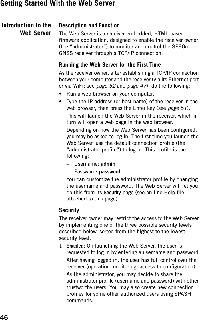
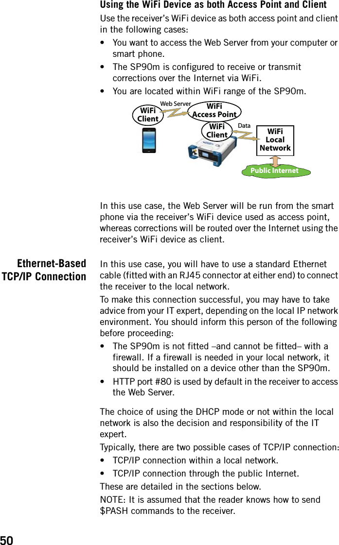
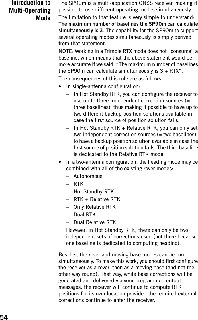
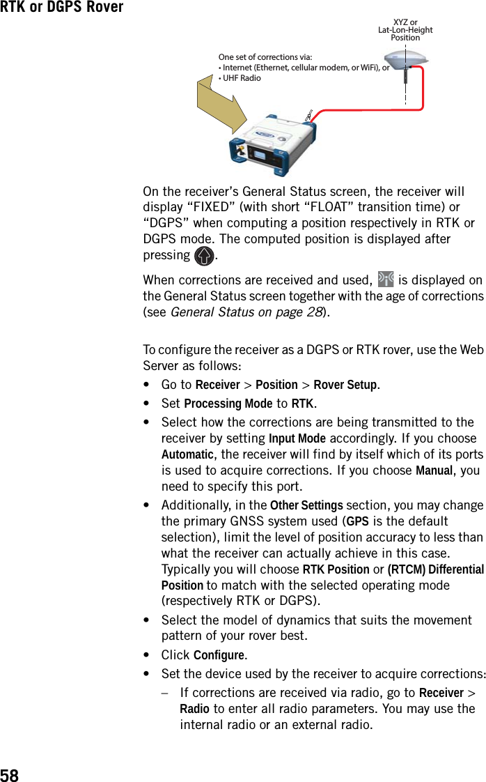
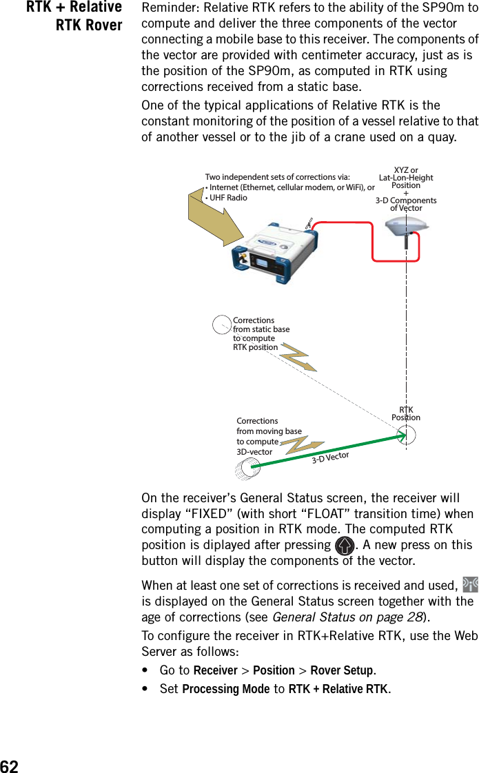
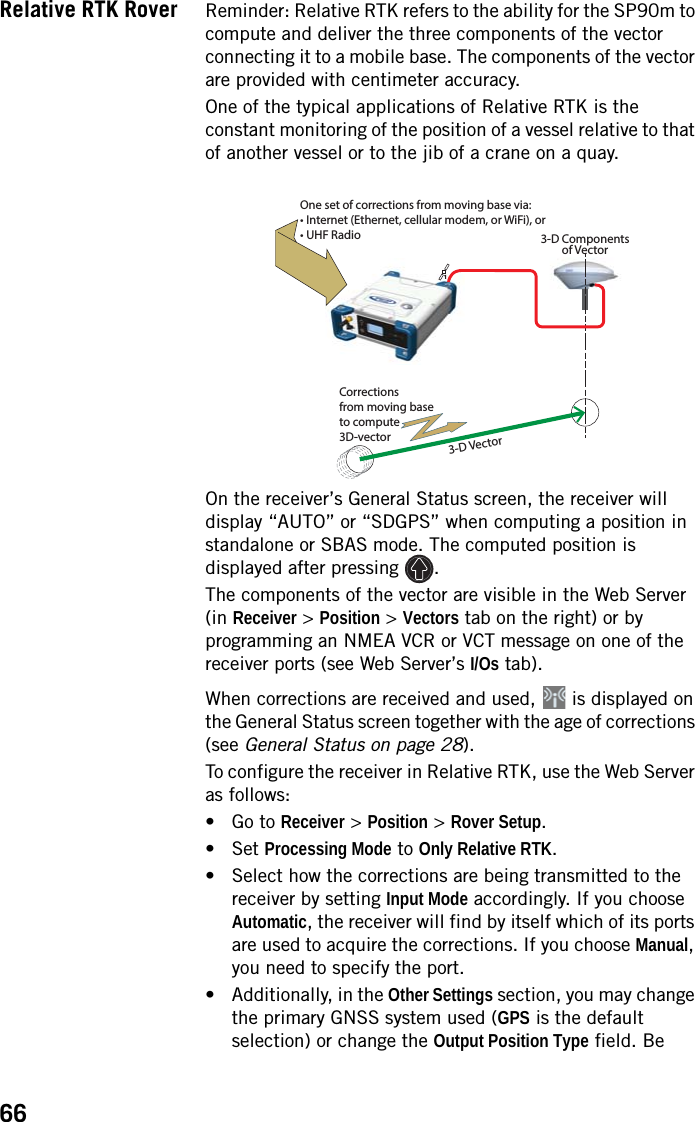

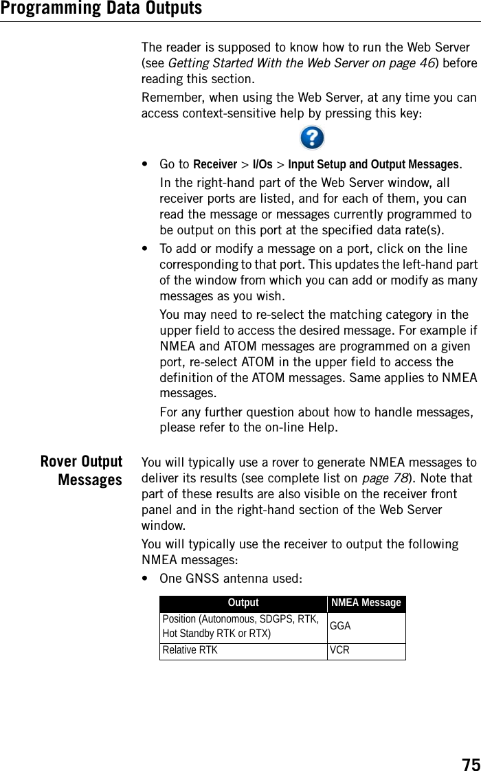
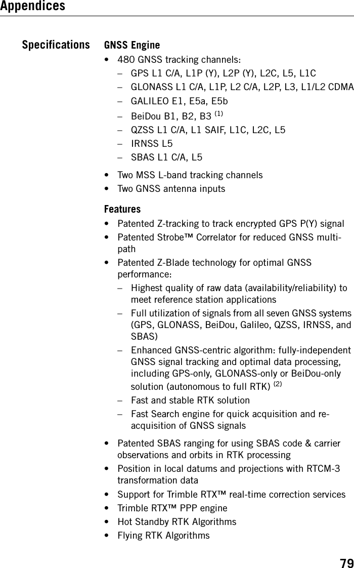
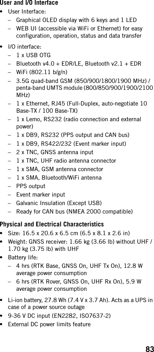
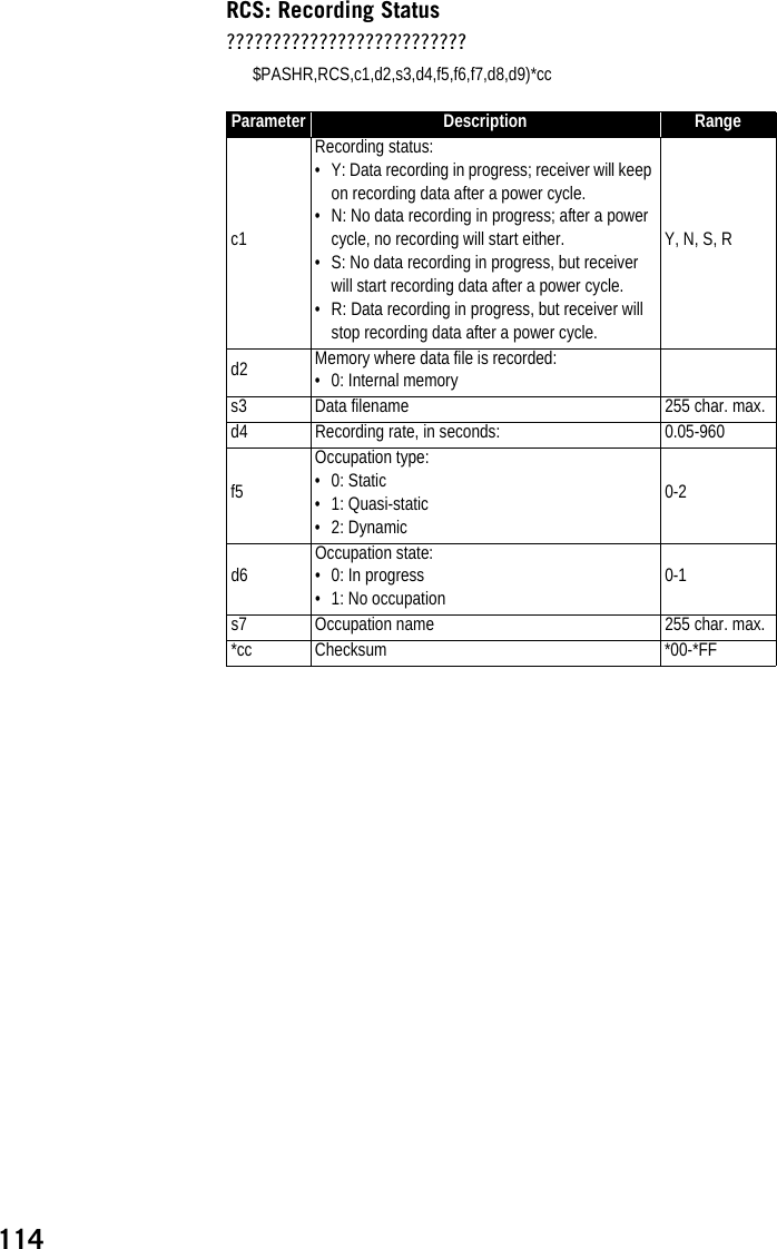
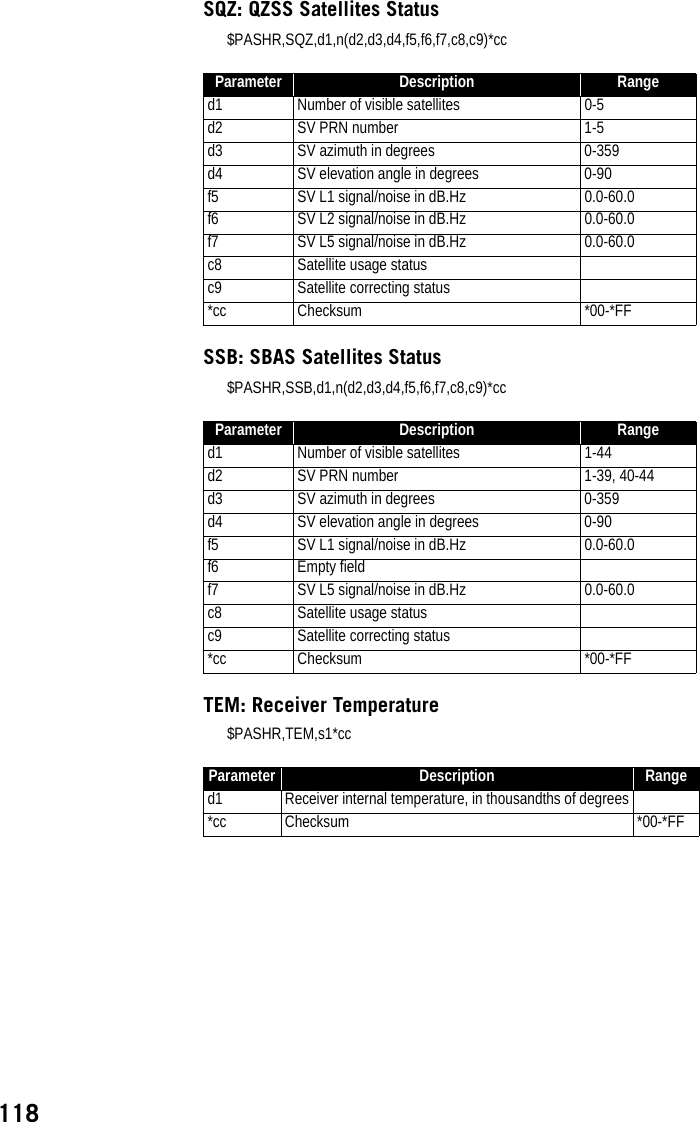
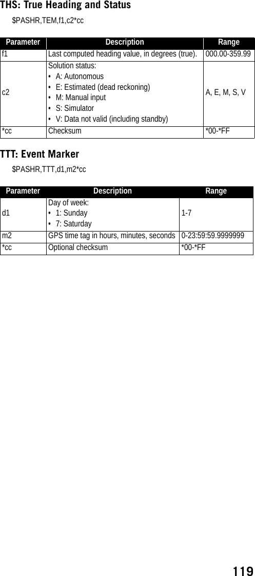
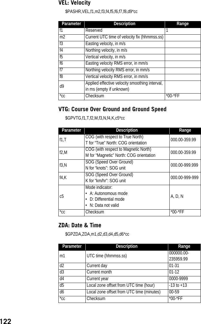
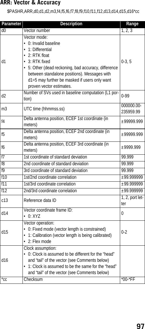
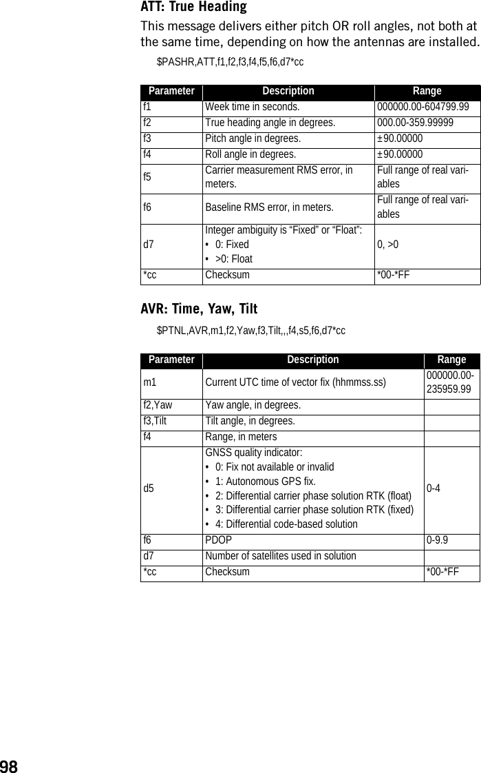
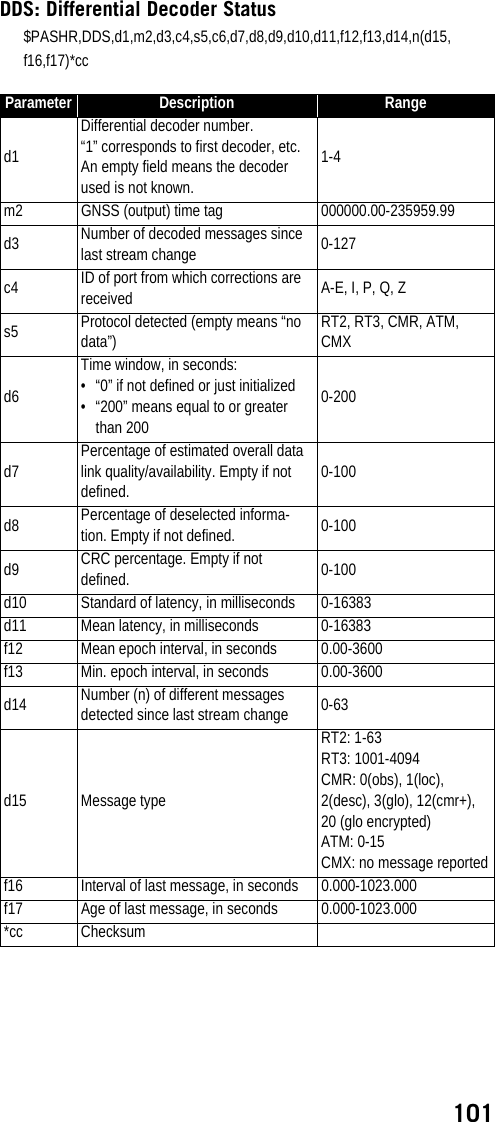
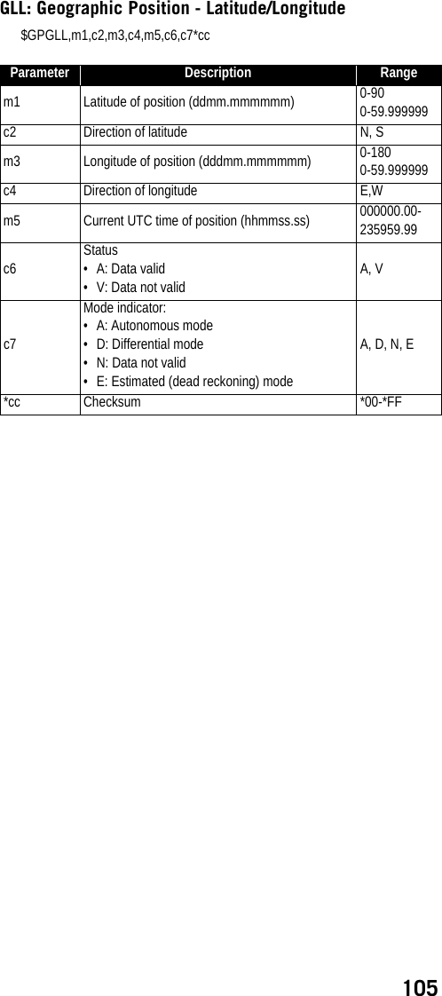
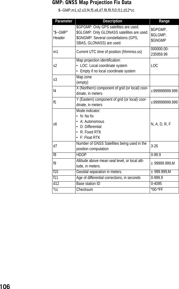
![92SP File ManagerSoftware UtilitySP File Manager allows you to copy “log” files and G-files directly from the receiver’s internal memory to the desired folder on your office computer.Additionally you can delete any G-file or “log” file from the receiver’s internal memory.G-files are GNSS raw data files in proprietary format (ATOM). “Log” files are editable text files listing all the operations performed by the receiver in one day.SP File Manager is available from the Spectra Precision website as an executable file (SPFileManagerSetup.exe) through the link below:http://www.spectraprecision.com/eng/sp90m.html#.WUjSUdxLdhE(Click on the Support tab to access the download link.)Installing SP File ManagerSP File Manager is very easy to install:• Download the executable file from the Spectra Precision website (use above link).• Double-click on the file to complete the installation.Connecting SP90m to your ComputerSP File Manager will use either a serial (RS232), Bluetooth or USB connection to communicate with the receiver. USB is recommended.Getting Started With SP File ManagerDouble-click on . The SP File Manager window which then appears is detailed below. [2][1][3][4]](https://usermanual.wiki/TRIMBLE-EUROPE/110610.Host-user-manual-2-SP90M-UG-B-Draft2-en-v2-pdf/User-Guide-3573060-Page-50.png)
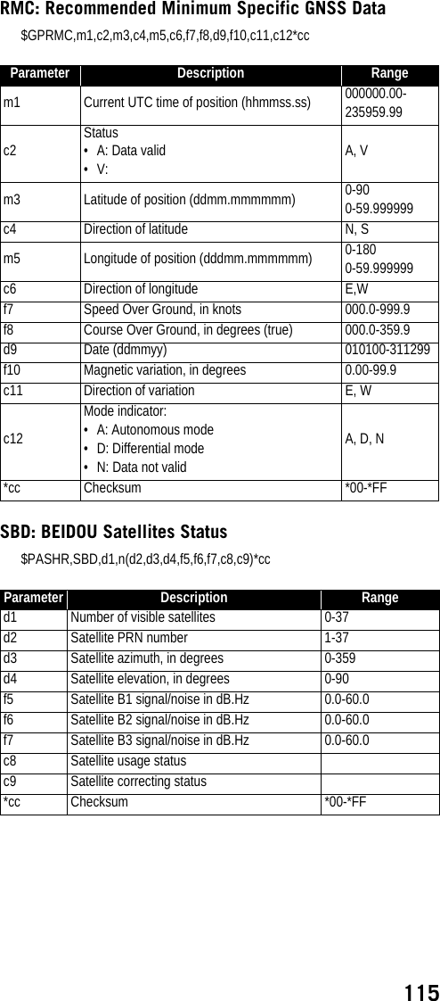
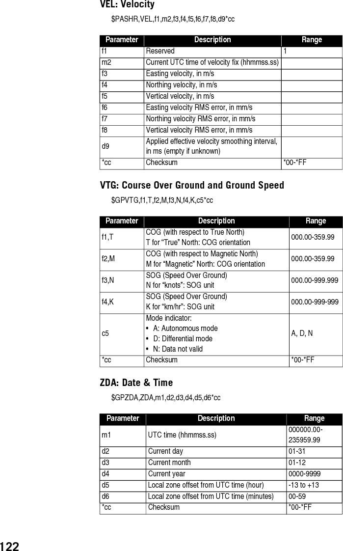
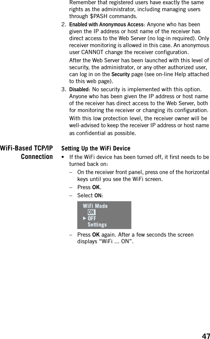
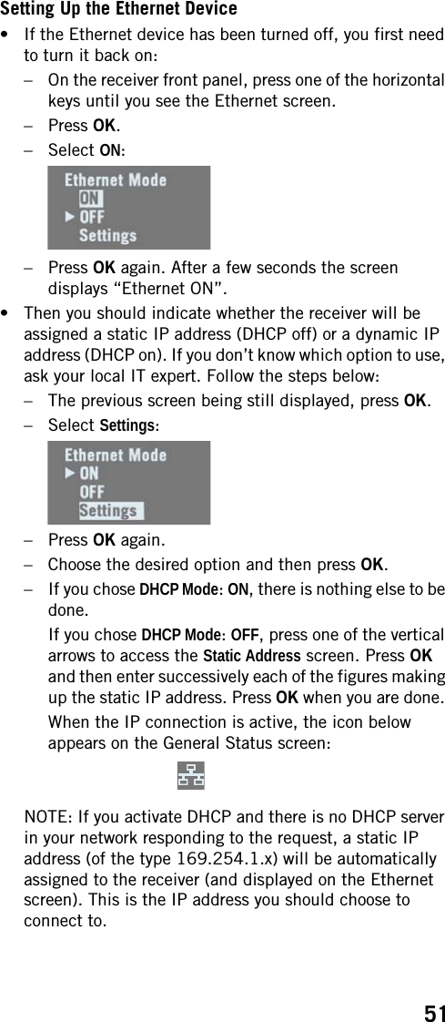
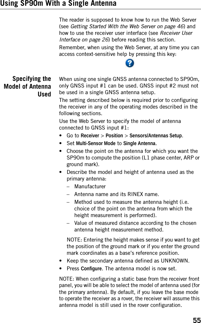
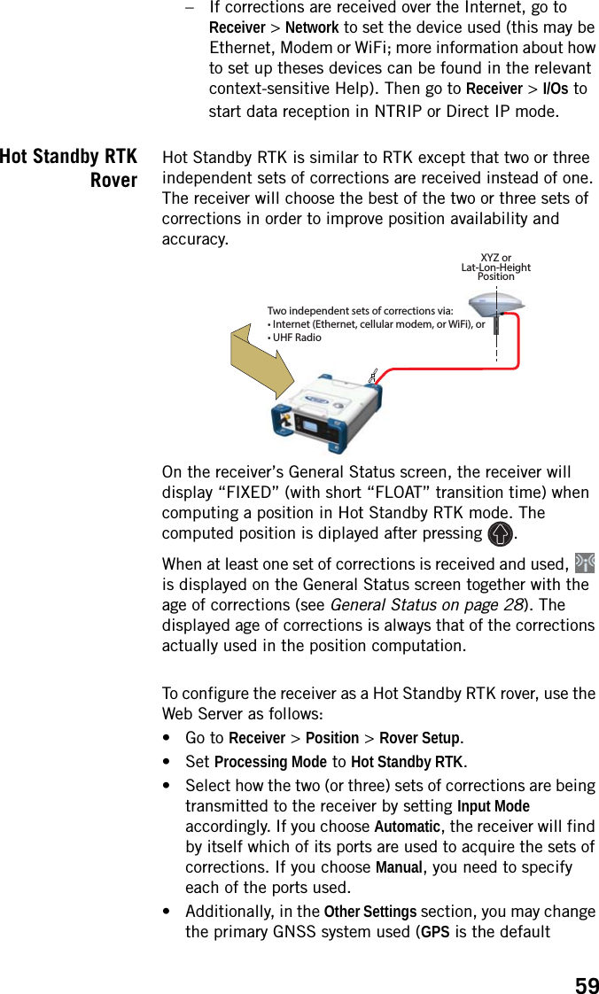
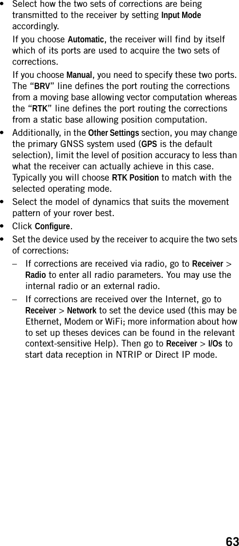
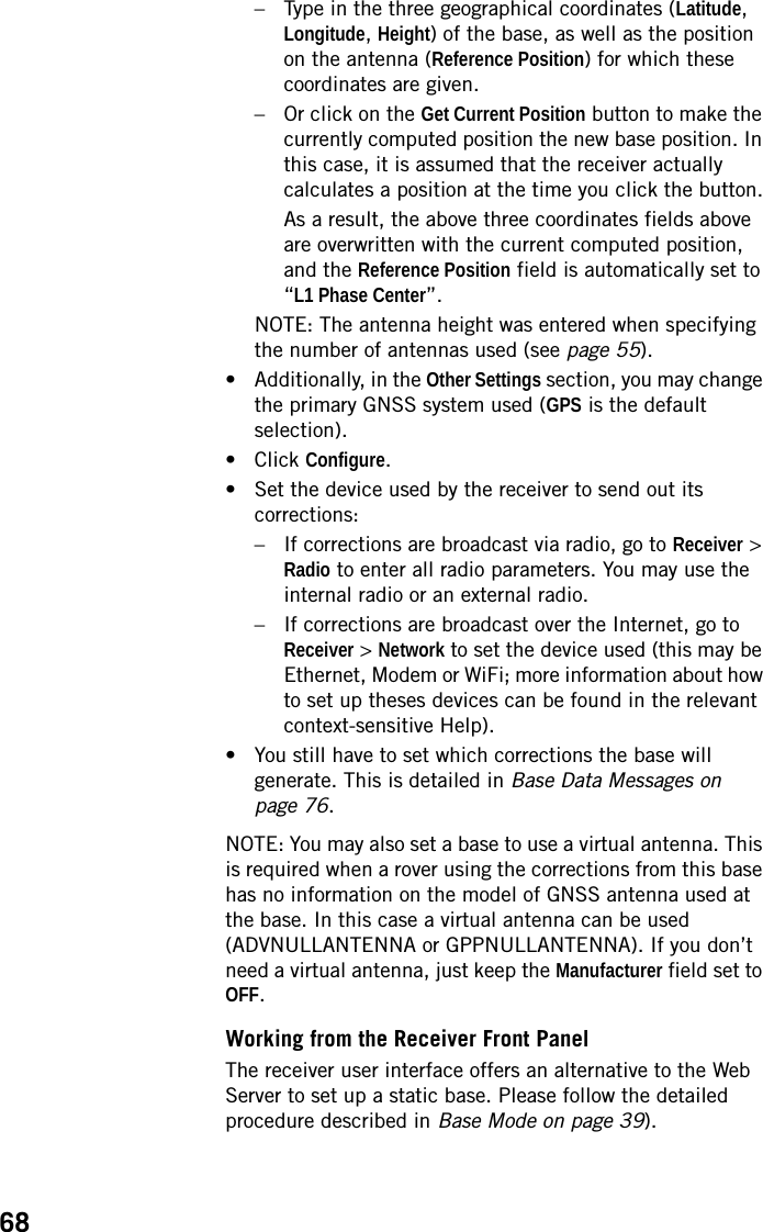
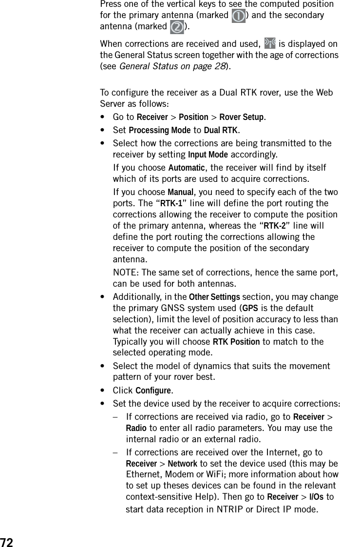
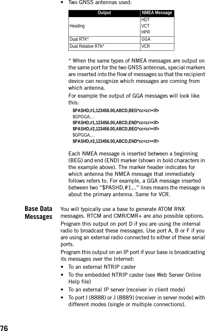
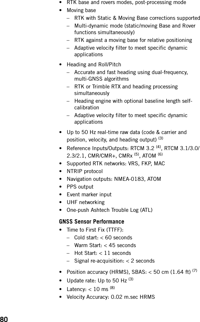
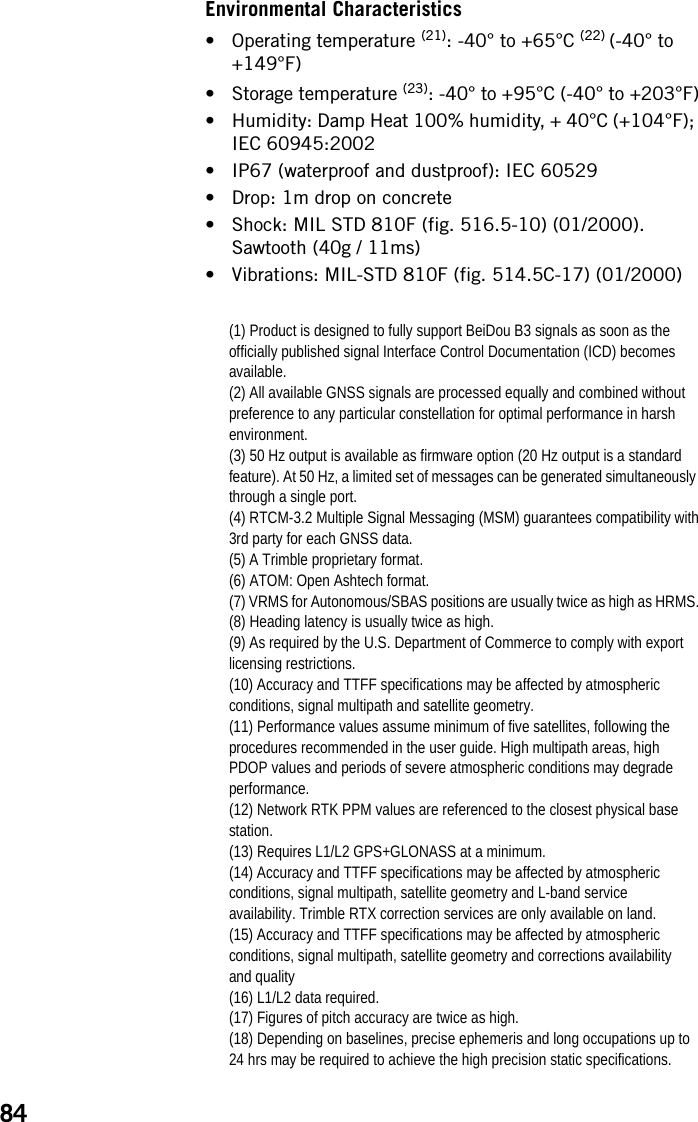
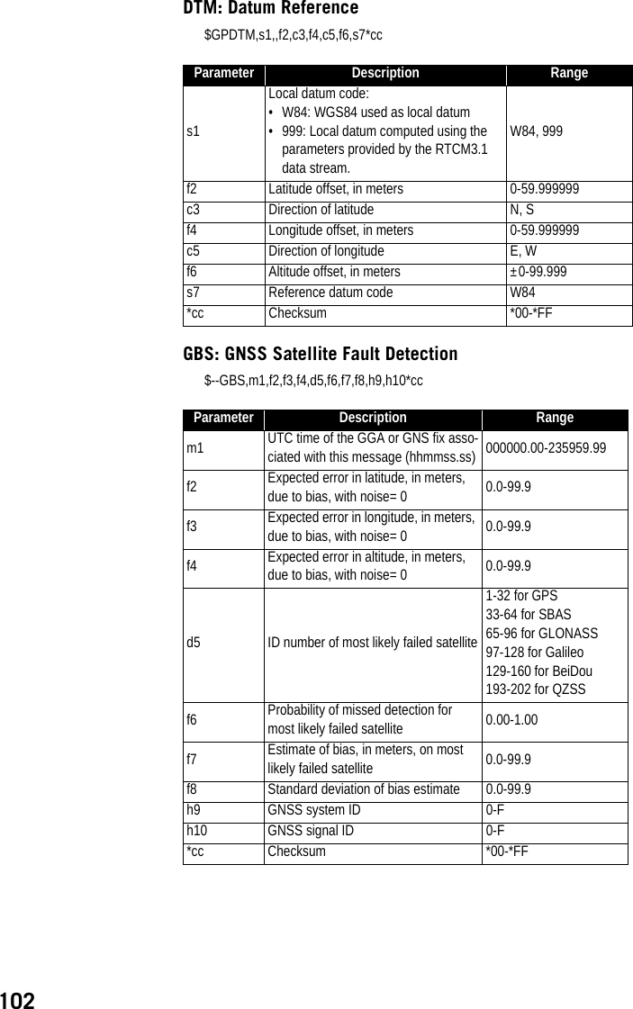
![93[1]: SP File Manager toolbar. This toolbar consists of the following items:•Port and baud rate scroll-down lists: Let you choose which serial port is used on computer side for the connection with the receiver (baud rate only makes sense when an RS232 serial line is used). Use 115200 Bd to communicate with SP90m.•Connect / Refresh button: Connect allows you to activate the connection between the computer and the receiver via the chosen serial line.When the connection is established, the button is changed into Refresh, which allows you to update the content of the two SP File Manager panes ([2] and [3] described below)•Disconnect button: Allows you to deactivate the connection currently established between the computer and the receiver.•Copy button: Copies the file(s) selected in pane [3] to pane [2]. In pane [2], you have to open the folder where to copy to before clicking on the Copy button.NOTE: Copied files have different creation dates and times compared to those of their respective original files. The new dates and times are those corresponding to when the files were copied.•Delete button: Deletes the files currently selected in pane [2] or [3].[2]: Pane showing the content of the currently open folder on computer side.[3]: Pane showing the content of the currently open folder on receiver side. The receiver’s root folder contains two to three sub-folders:•Internal memory: Lists all G-files recorded by the receiver in its internal memory•Log files: Contains log files (one per day). Each log file lists all the actions performed by the receiver in one day.•USB key, if one is currently connected to the receiver.To open a folder, double-click on it. To go back to the parent folder, click on .[4]: Pane showing copy/delete operations in progress, and all those completed since the connection with the receiver was established. This pane is cleared at the beginning of each new working session of SP File Manager.](https://usermanual.wiki/TRIMBLE-EUROPE/110610.Host-user-manual-2-SP90M-UG-B-Draft2-en-v2-pdf/User-Guide-3573060-Page-51.png)
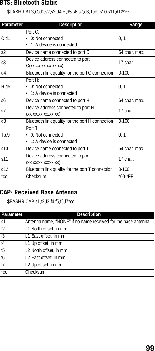
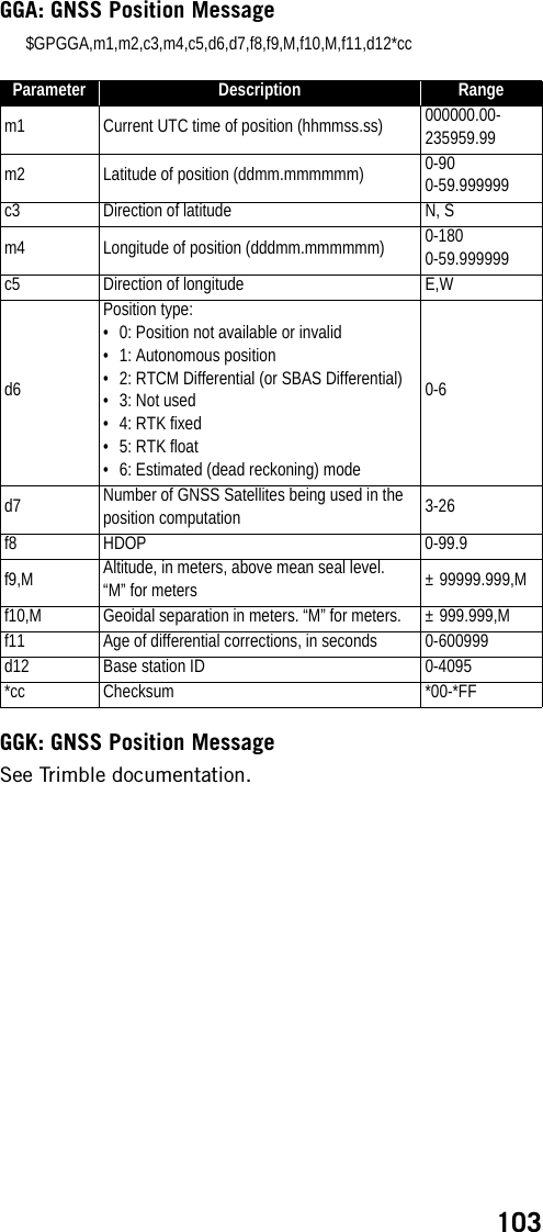
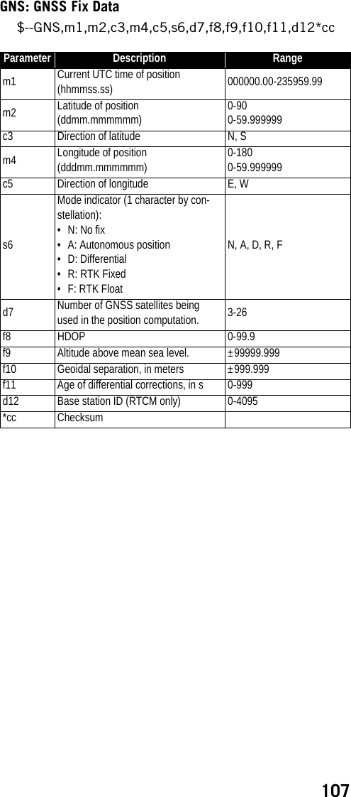
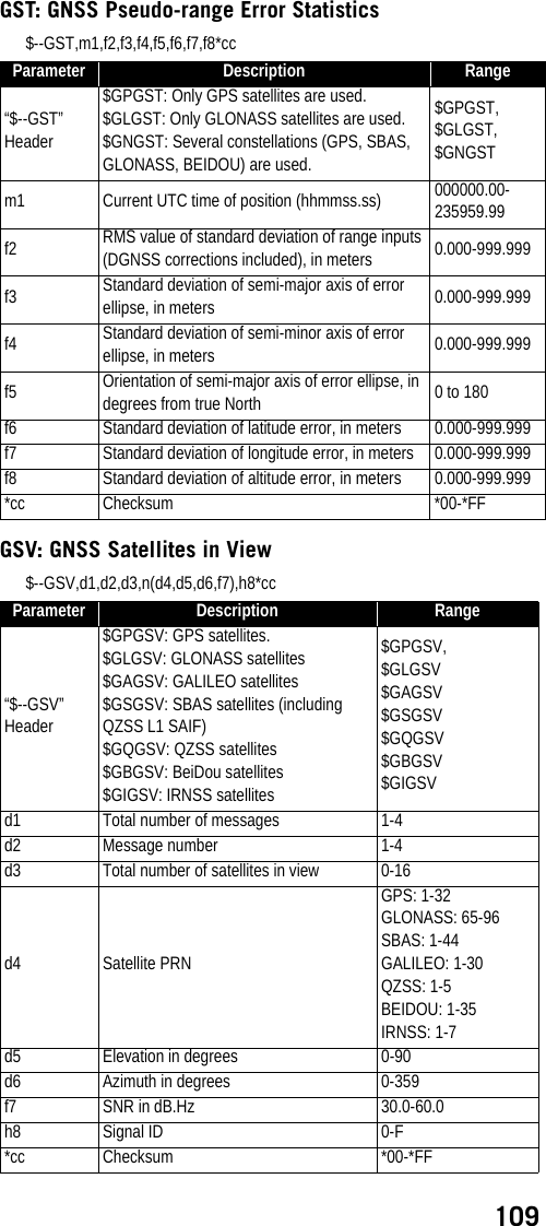
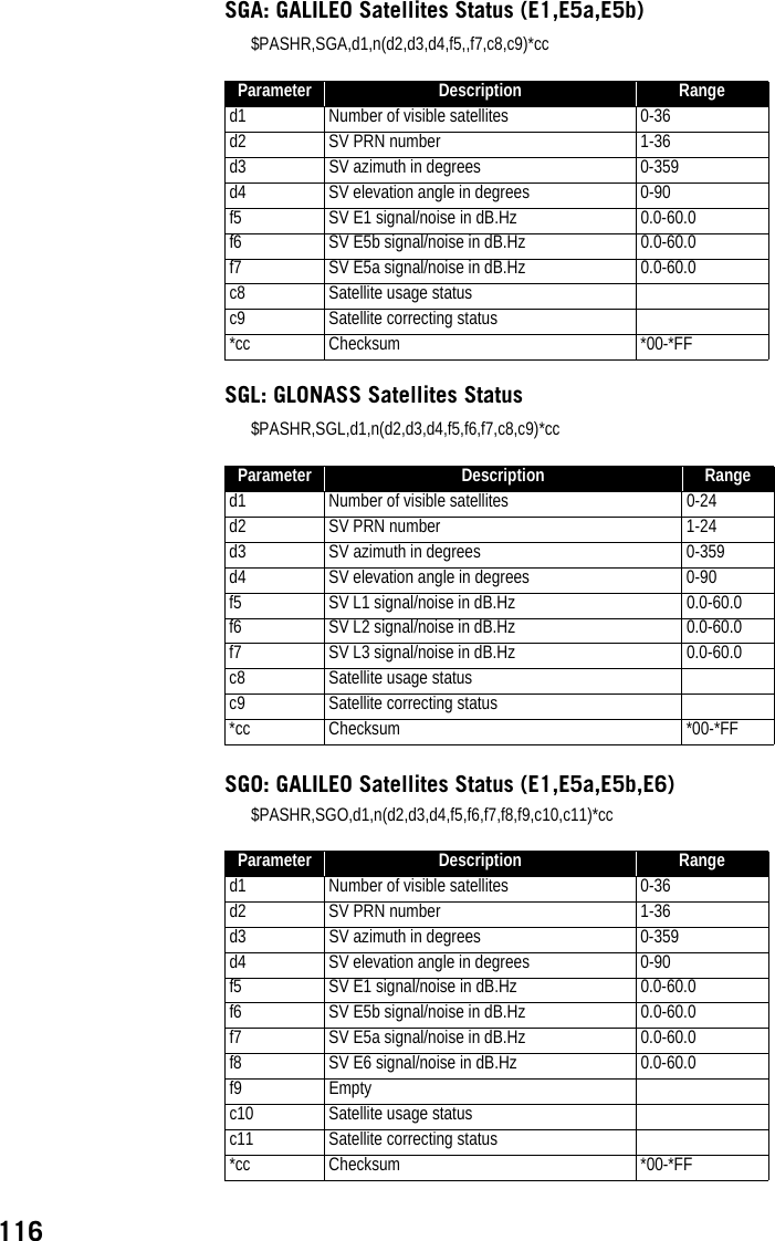
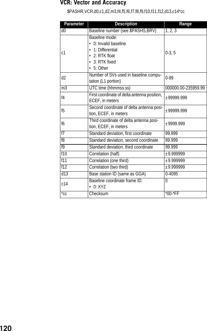
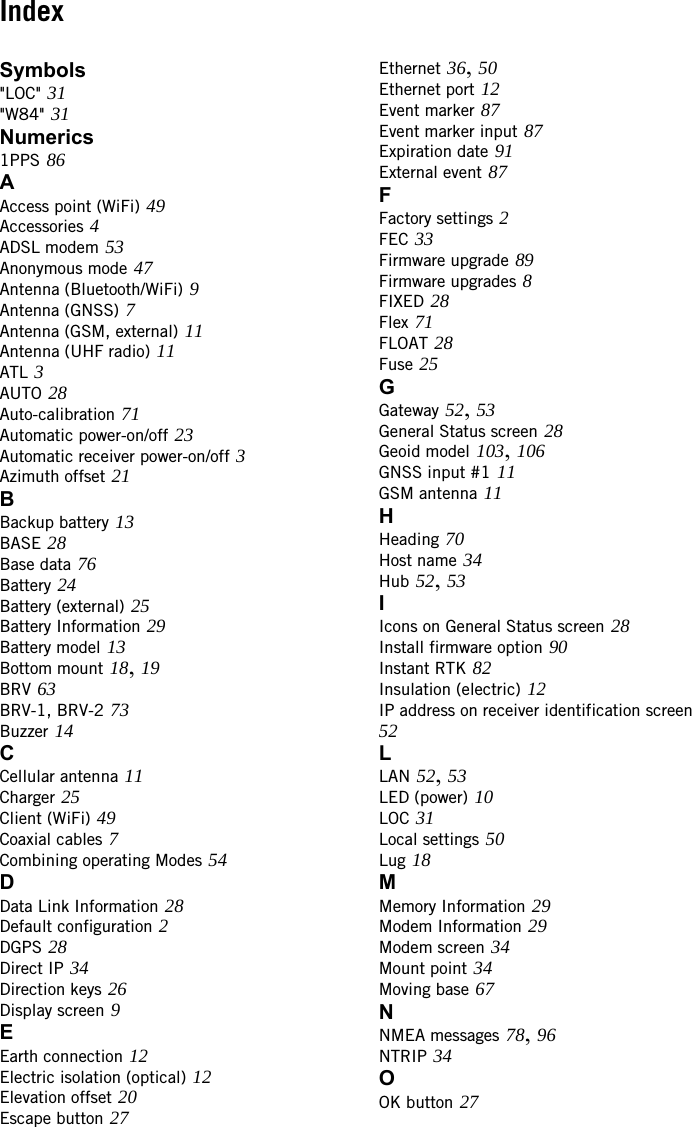
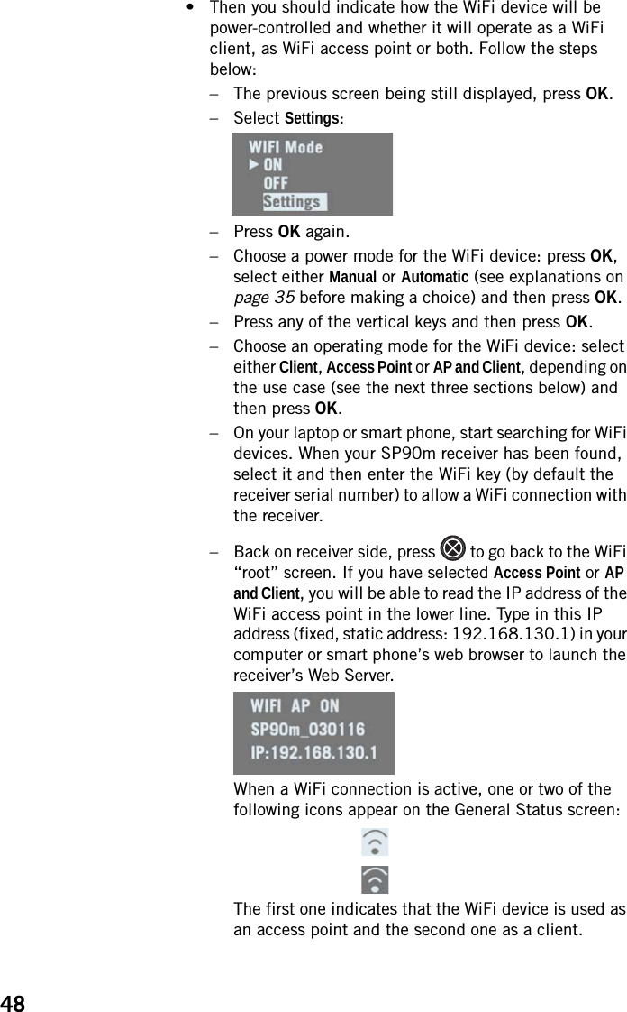
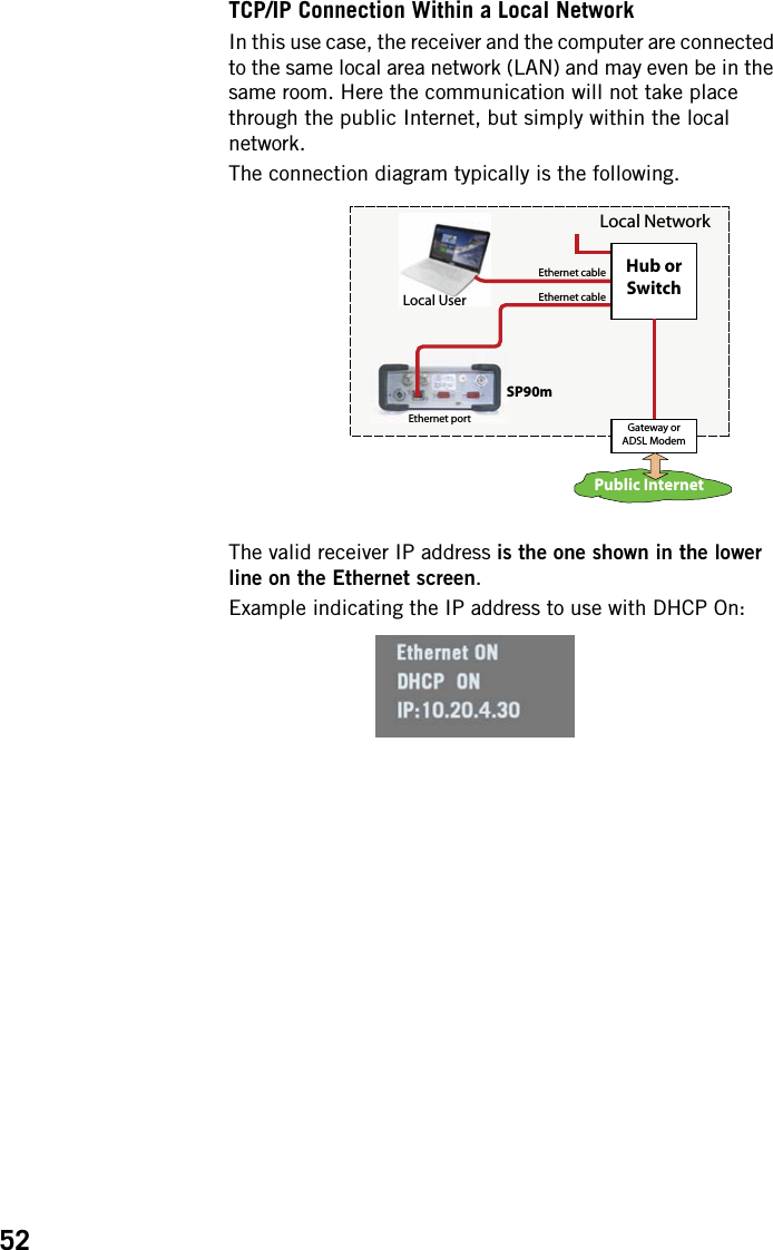
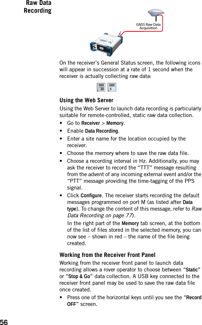
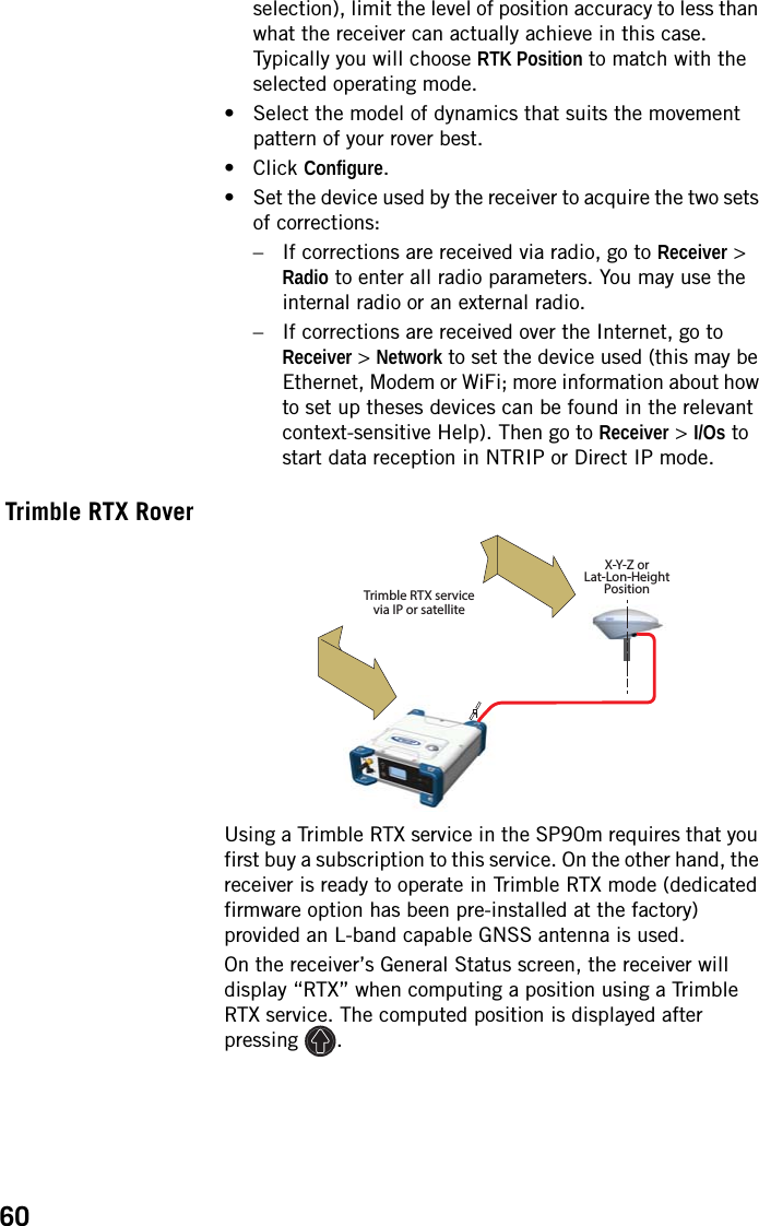
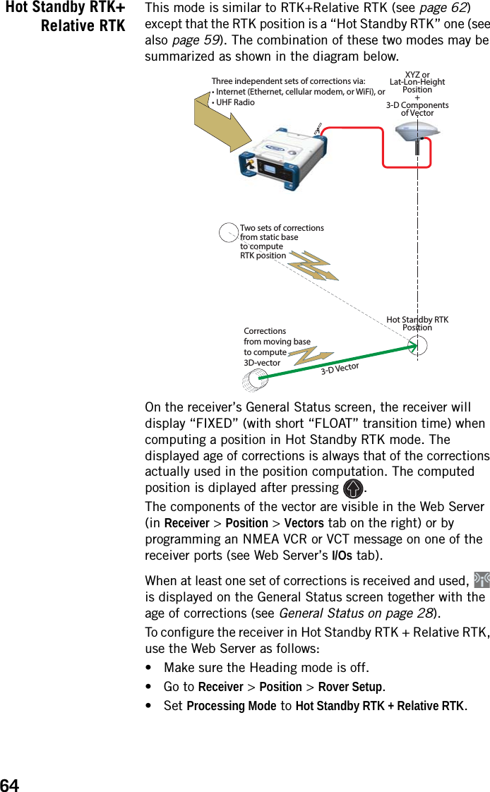
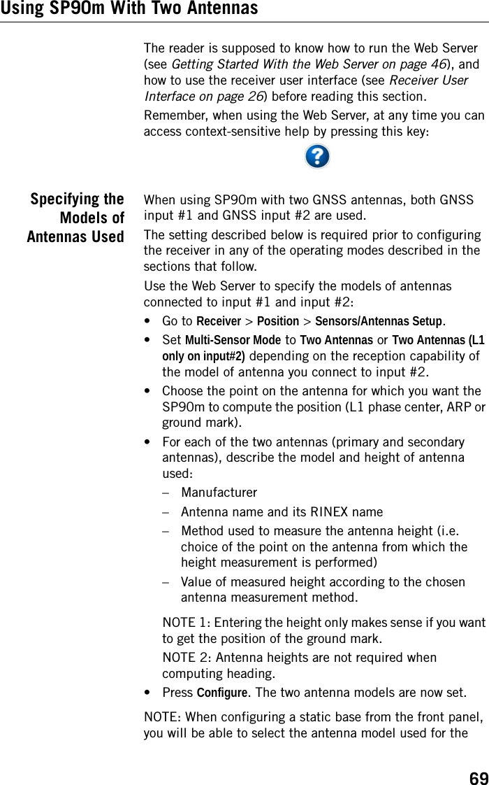
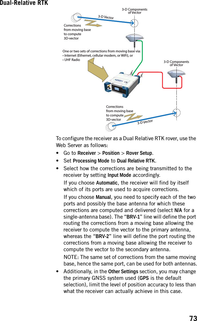
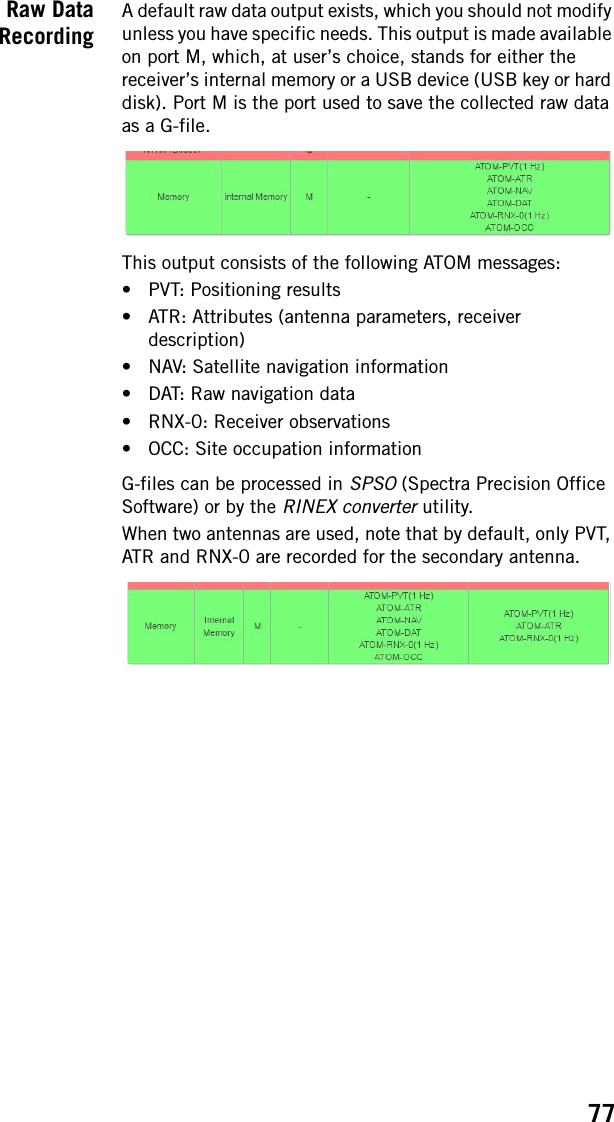
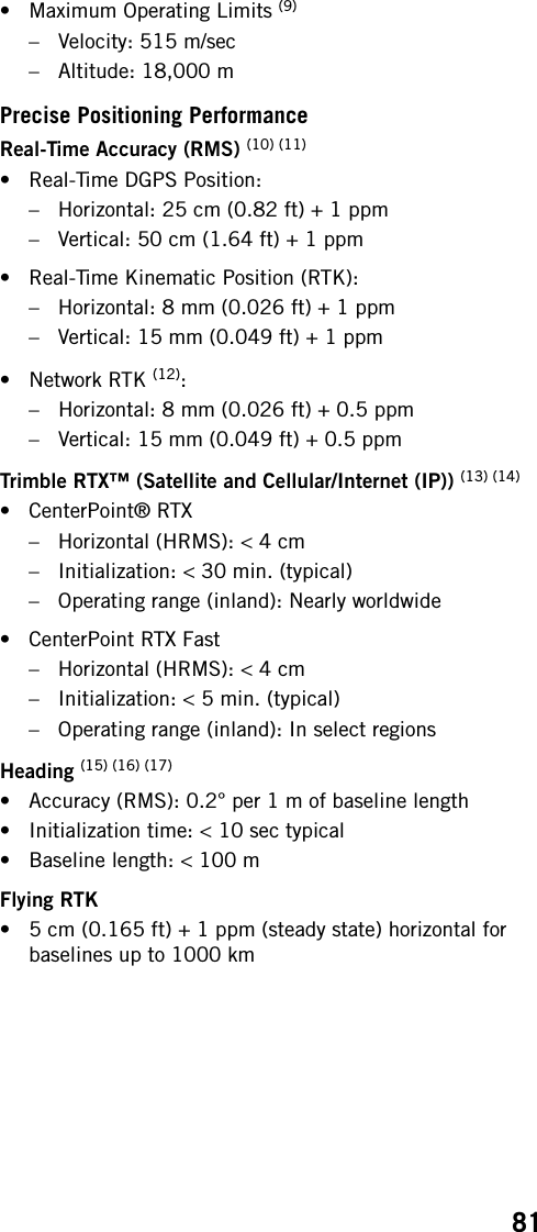
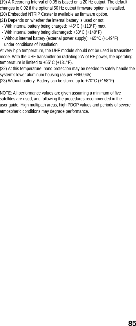
![111LTN: Latency$PASHR,LTN,d1*ccMDM: Modem State and Parameter$PASHR,MDM,c1,d2,s3,PWR=s4,PIN=s5,PTC=d6,CBS=d7,APN=s8,LGN=s9,PWD=s10,PHN=s11,ADL=c12,RNO=d13,MOD=s14,NET=d15,ANT=s16*ccParameter Description Ranged1 Latency in milliseconds.*cc Optional checksum *00-*FFParameter Description Rangec1 Modem port Ed2 Modem baud rate 9s3Modem state.“NONE” means that MODEM option [Z] is not valid.OFF, ON, INIT, DIALING, ONLINE, NONEPWR=s4Power mode:• AUT: Automatic• MAN: ManualAUT, MANPIN=s5 PIN code 4-8 digitsPTC=d6Protocol:•0: CSD•1: GPRS0-1CBS=d7Not usedCSD mode:• 0: V.32 9600 bauds• 1: V.110 9600 bauds ISDN0-1APN=s8 Access Point Name (GPRS) 32 char. max.LGN=s9 Login (GPRS) 32 char. max.PWD=s10 Password (GPRS) 32 char. max.PHN=s11 Phone number (CSD) 20 digits max.ADL=c12 Auto-dial mode Y, NRNO=d13 Maximum number of re-dials (CSD) 0-15MOD=s14 Modem model (empty if unknown) Centurion PHS8NET=d152G/3G selection mode:• 0: Automatic (2G or 3G)• Forced to operate in 2G0-1ANT=S16GSM antenna used:• INT: Internal• EXT: ExternalINT, EXT*cc Checksum *00-*FF](https://usermanual.wiki/TRIMBLE-EUROPE/110610.Host-user-manual-2-SP90M-UG-B-Draft2-en-v2-pdf/User-Guide-3573060-Page-69.png)
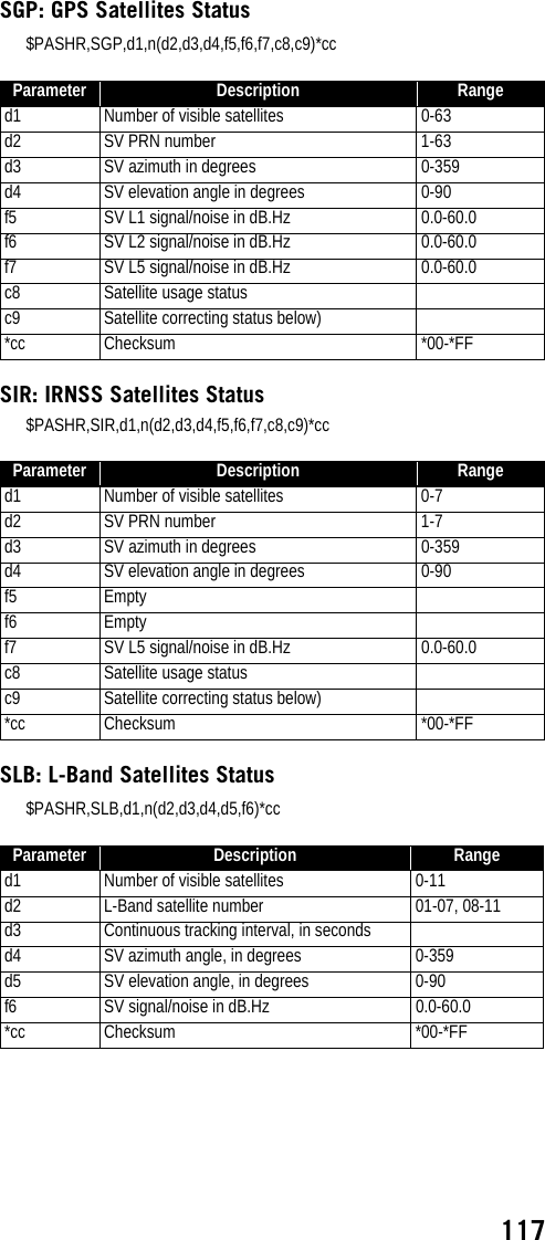
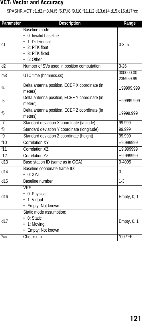
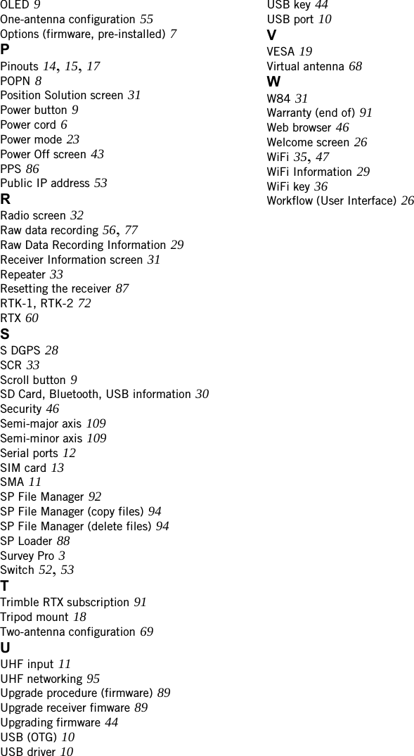
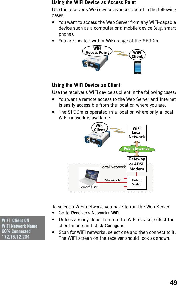
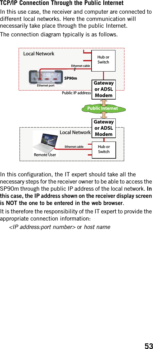
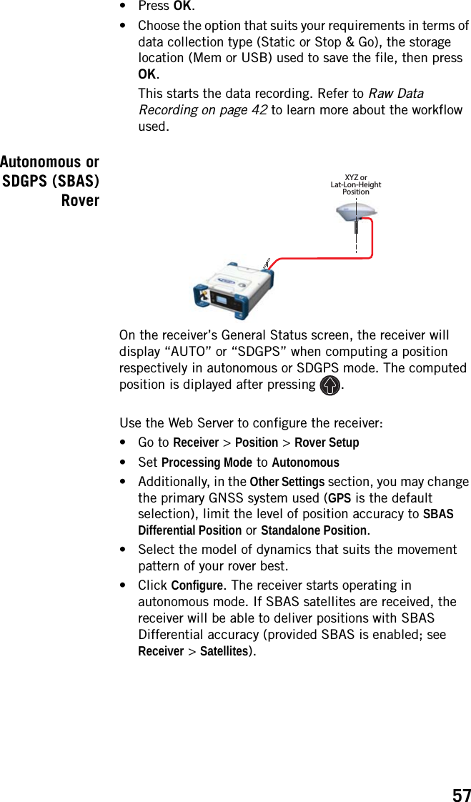
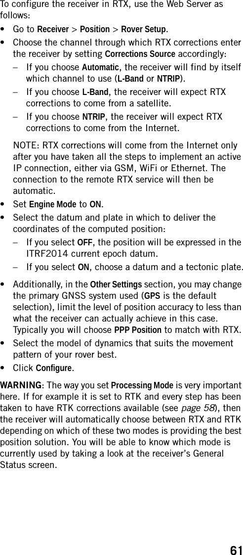
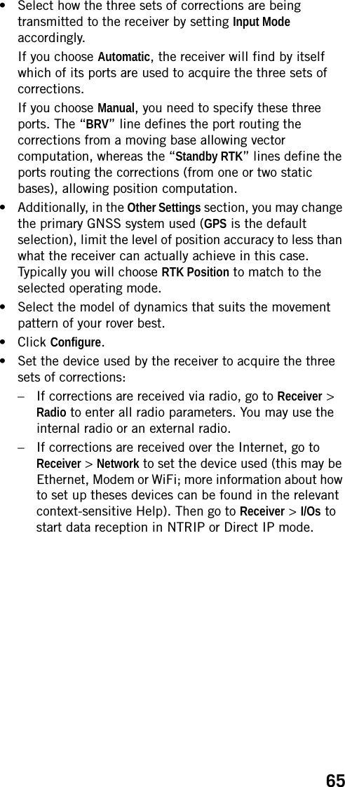
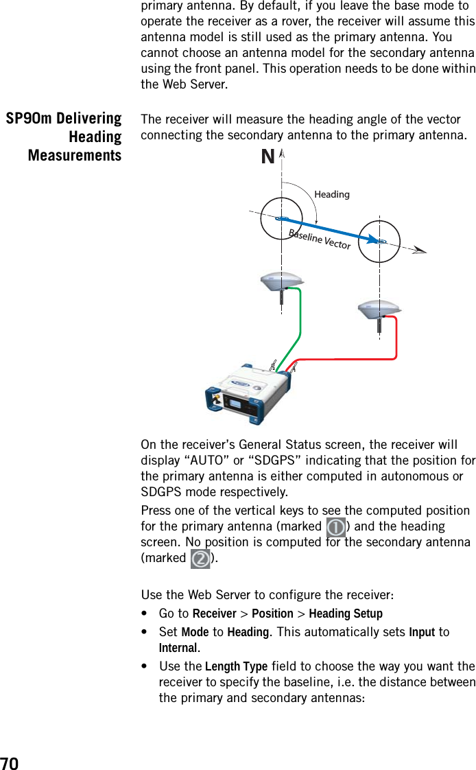
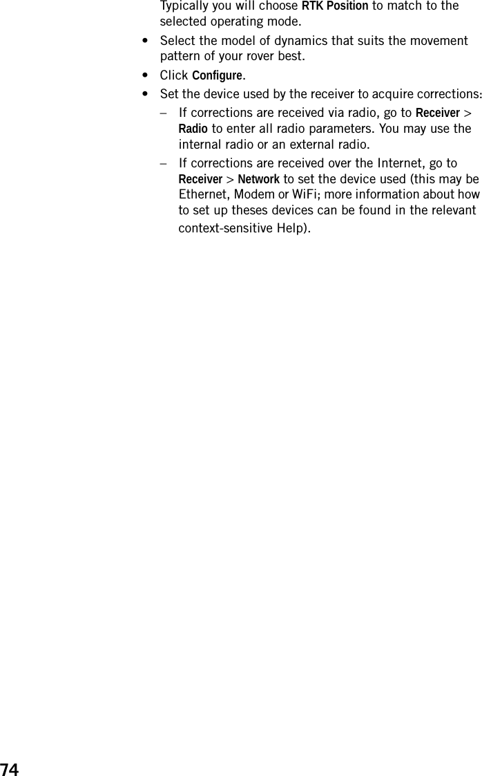
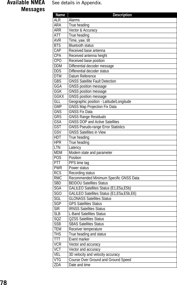
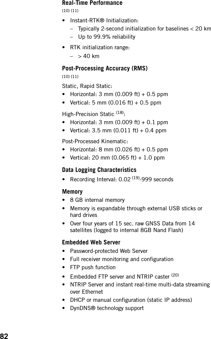
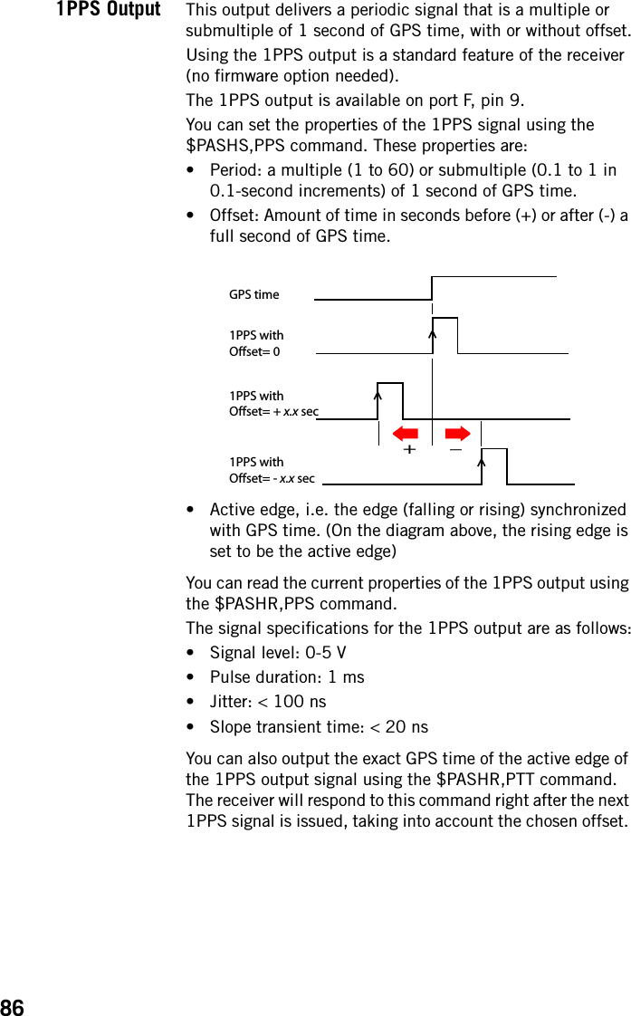
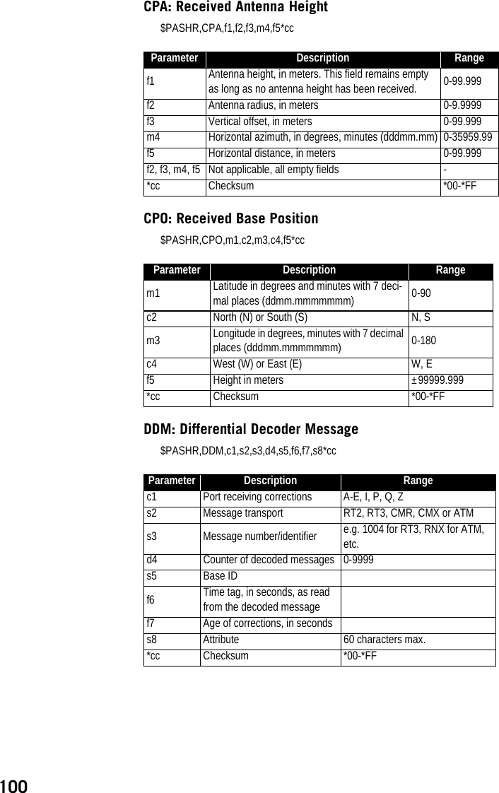
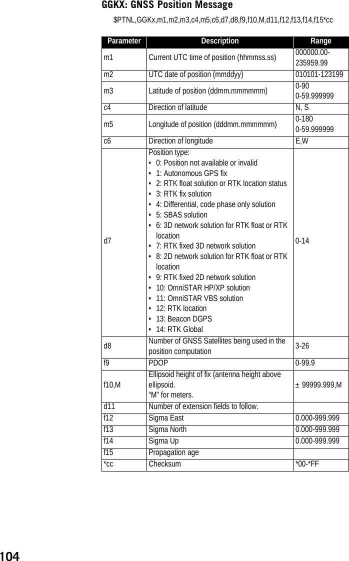
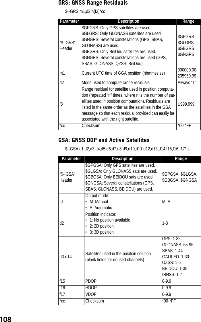
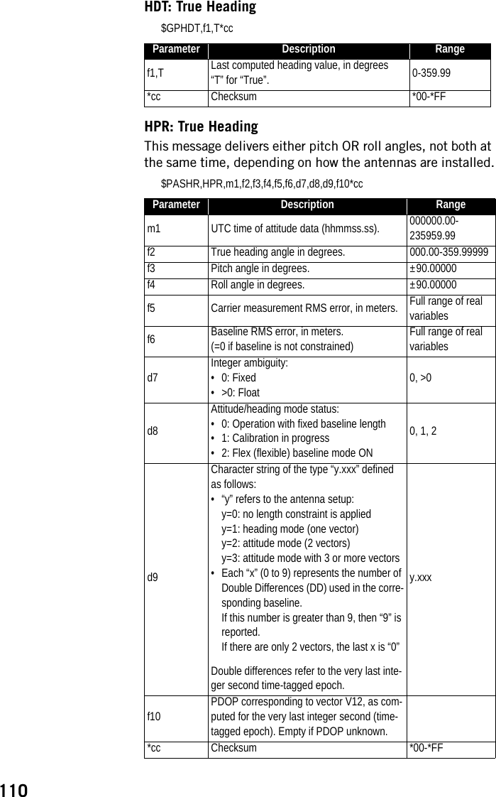
![113PTT: PPS Time Tag$PASHR,PTT,d1,m2*ccPWR: Power Status$PASHR,PWR,d1,[f2],[f3],[d4],[d5],[f6],[d7],[d8],d9[,d10]*ccParameter Description Ranged1Day of week:• 1: Sunday• 7: Saturday1-7m2 GPS time tag in hours, minutes, seconds 0-23:59:59.9999999*cc Checksum *00-*FFParameter Description Ranged1Power source:• 0: Internal battery• 1: External battery• 2: External DC source0-2f2 Output voltage of battery (internal), in volts 0.0-12.0f3 Emptyd4 Percentage of remaining battery energy 0-100d5 Emptyf6 DC input voltage from external power, in volts 0.0-30.0d7Battery charging status:• 0: Charging• 1: Discharging• 2: Fully charged• 3: Fully discharged0-3d8 Emptyd9 Internal temperature, in degrees Cd10 Battery temperature, in degrees C*cc Checksum *00-*FF](https://usermanual.wiki/TRIMBLE-EUROPE/110610.Host-user-manual-2-SP90M-UG-B-Draft2-en-v2-pdf/User-Guide-3573060-Page-71.png)