TRIMBLE EUROPE 110610 GSM/GPRS/UMTS/HSPA Module User Manual SP90MUG
TRIMBLE EUROPE BV GSM/GPRS/UMTS/HSPA Module SP90MUG
Contents
- 1. Host user manual 1_SP90M_UG_B_Draft2_en-v1a.pdf
- 2. Host user manual 1_SP90M_UG_B_Draft2_en-v1b.pdf
- 3. Host user manual 2_SP90M_UG_B_Draft2_en-v2.pdf
- 4. User guide_SP85_UG_A_en-part2_Part1
- 5. User guide_SP85_UG_A_en-part2_Part2
- 6. User guide_SP85_UG_A_en-part2_Part3
- 7. User guide_SP85_UG_A_en-part2_Part4
Host user manual 1_SP90M_UG_B_Draft2_en-v1b.pdf
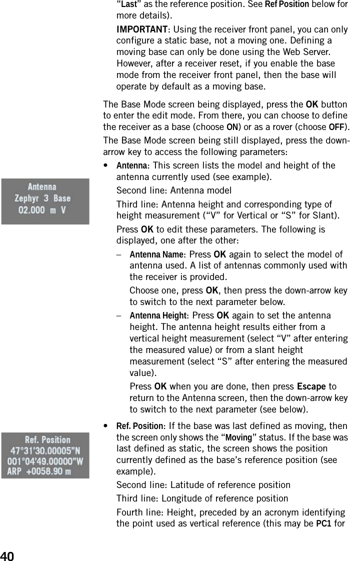
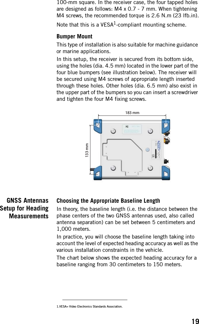
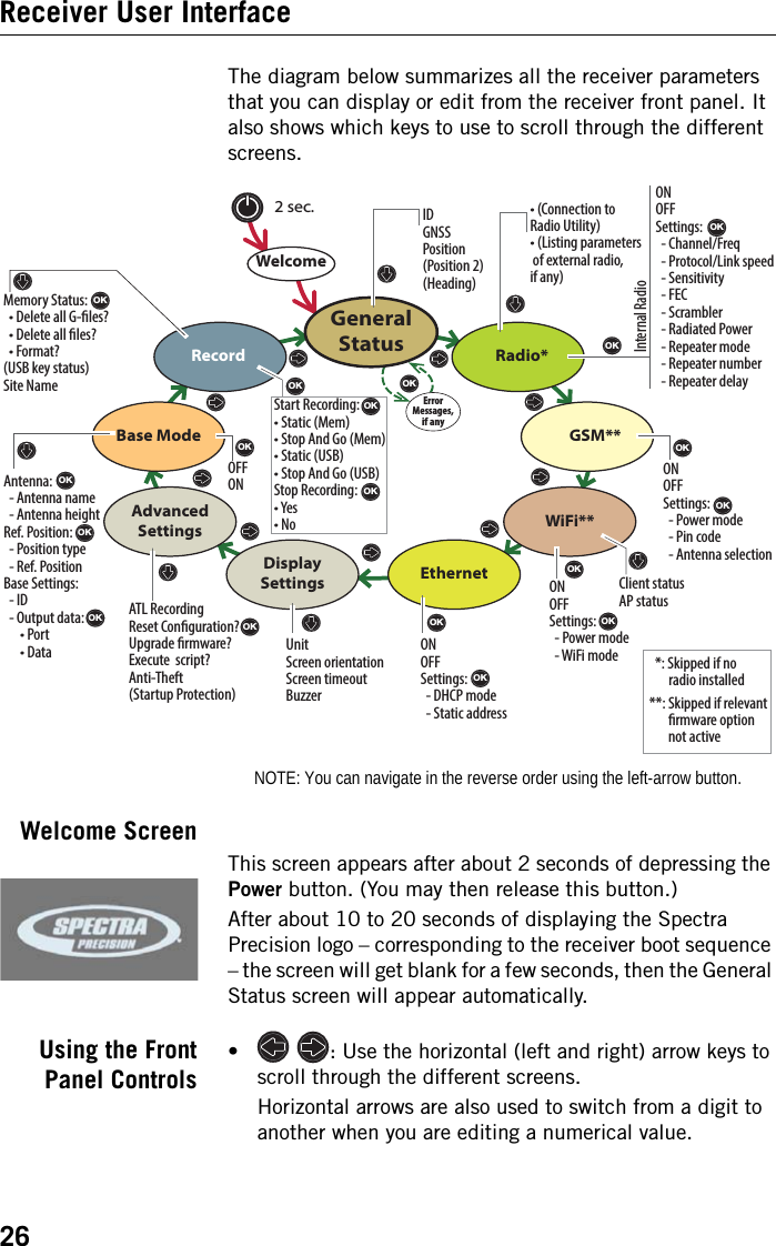
![18 Installation InstructionsReceiver NOTE: Depending on how you install the receiver, you may need to change the orientation of the displayed data on the front panel screen. This is possible using one of the options in the Display Settings menu (see page 36).Tripod MountIn land surveying applications, for example when used as a roaming base mounted on a tripod, the SP90m can be secured on one of the legs of the tripod using the lug ([A]) fastened on its bottom side (see illustration below).The lug may be secured onto the receiver case in two different ways allowing the receiver to be installed either with its front panel upwards ([1]) or sideways ([2]) (recommended).Bottom Plane MountThis type of installation is suitable for machine guidance or marine applications. The SP90m is secured from underneath the receiver case, using four screws M4.Preparing the support on which the receiver will be mounted only consists of drilling four holes, forming a simple, [1] [A][2]100 mm100 mm](https://usermanual.wiki/TRIMBLE-EUROPE/110610.Host-user-manual-1-SP90M-UG-B-Draft2-en-v1b-pdf/User-Guide-3573048-Page-2.png)

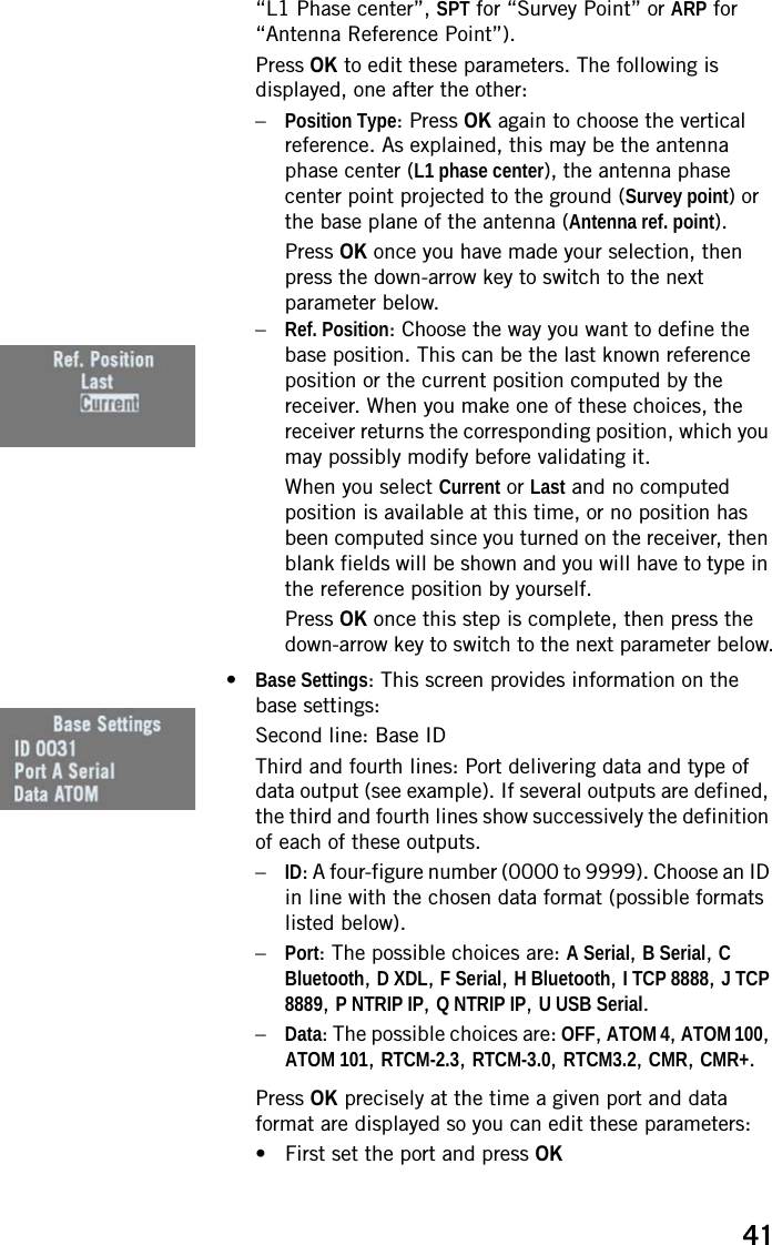
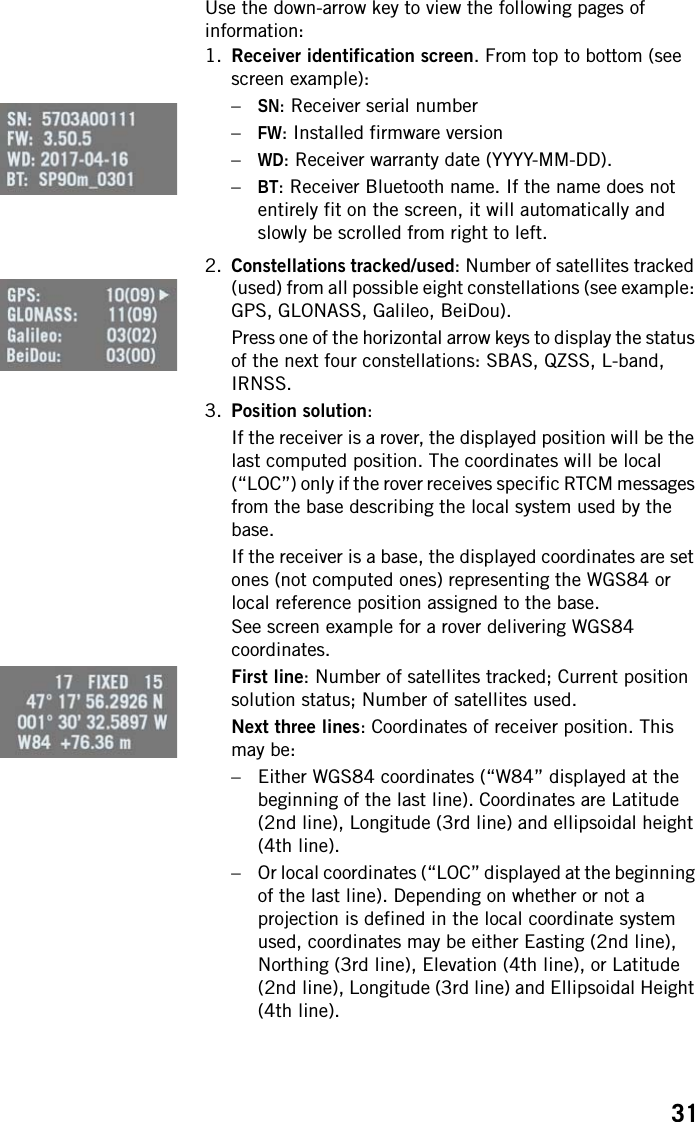
![21antennas after measuring the elevation deviation and the baseline length. The sign of the elevation offset is also provided on the diagram below (elevation offset negative if the secondary antenna is lower than the primary antenna and vice versa).The elevation offset should not be more than 45 degrees (or less than -45 degrees), or the receiver will consider the antenna setup to be invalid. No heading, roll or pitch measurements would be calculated in this case.Azimuth OffsetIdeally, the two antennas should be installed in such a way that the baseline direction is strictly parallel or perpendicular to the vehicle centerline.However, you may also be facing some installation constraints on your vehicle compelling you to install the antennas differently. The azimuth offset describes the non-alignment of the baseline with respect to the vehicle centerline.When the baseline is strictly parallel to the centerline and it is oriented in the direction of forward movement, the azimuth offset is zero. In all other cases, the offset is non-zero and should be measured as shown in the diagram below.The non-alignment of the baseline with respect to the vehicle centerline may be intentional (see explanations in the next section below).Baseline length Baseline Length (m) Elevation Deviation (m) Elevation Deviation Secondary AntennaPrimary AntennaElevation Offset (°)Elevation Offset (°) = arcsin [+] [-] Vehicle Centerline Azimuth Offset (°)Secondary AntennaPrimary Antenna Baseline Direction Forward movement](https://usermanual.wiki/TRIMBLE-EUROPE/110610.Host-user-manual-1-SP90M-UG-B-Draft2-en-v1b-pdf/User-Guide-3573048-Page-5.png)


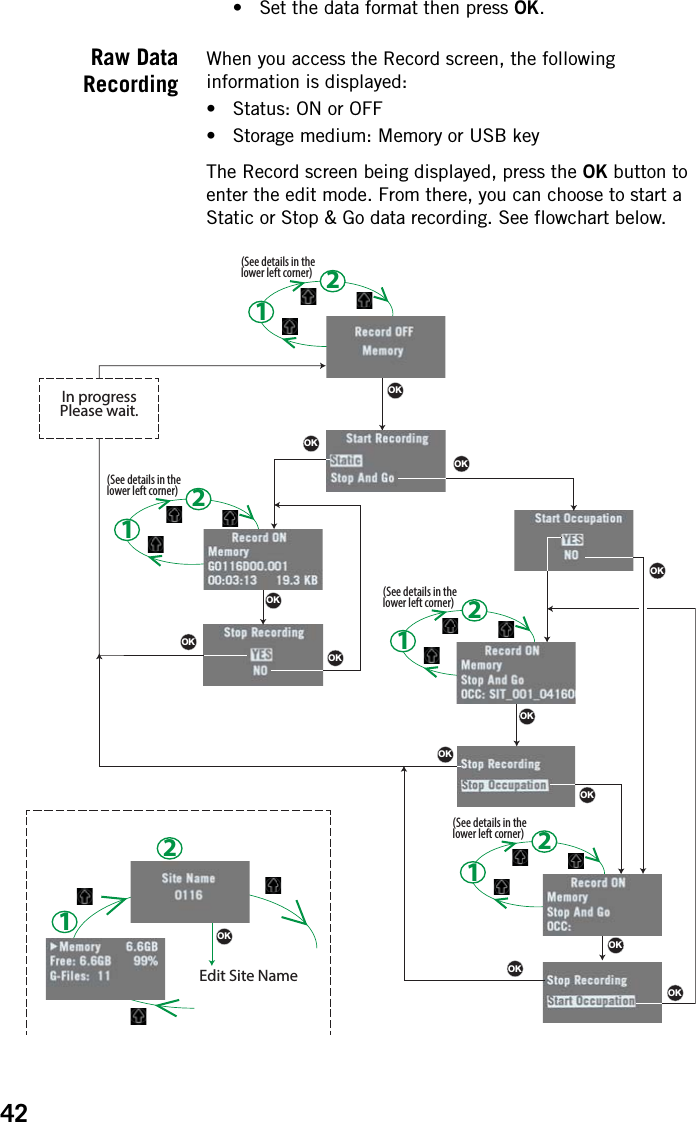
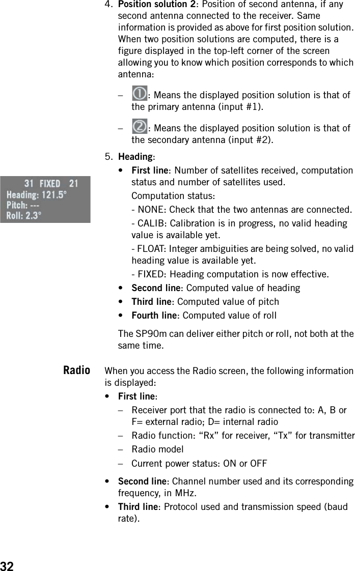
![28General Status See examples below for a rover (left) and a base (right). Refer to the tables below for more details on each of the icons or data reported on this screen.NOTE: In the secondcolumn, the slash symbol(“/”) is used between iconsto indicate that these iconsoccupy the areasuccessively at theindicated displaying rate.[1] [2] [3] [4][5] [6][1] [2] [3] [4][12][7] [8] [10][11][9] [12][7] [8] [10][11][9][5] [6][13]Area Icon or Data Reported Meaning[1]Anti-theft or/and startup protection active (solid icon).Receiver running after entering startup protection password. Startup protection still active and will require same password at next power up.One or more alarms set (blinking icon). Press the Scroll button as many times as necessary to read and acknowledge the alarms. / One or more alarms set and anti-theft or/and startup protection active. Icons appear in succes-sion every 1 second.(Blank) No alarm set and anti-theft protection inactive.[2] {a number} Total number of satellites from all GNSS constella-tions visible (tracked) from the current location.[3] {a text string}Position solution status:– NONE: Position not available– AUTO: Autonomous GNSS position– DGPS: Differential GNSS position– SDGPS: SBAS Differential GNSS position– BDGPS: BeiDou only position solution– FLOAT: Float solution– FIXED: Fixed solution (RTK is operational)– RTX: CenterPoint® RTX solution– BASE: Receiver configured as a base.[4] {a number}Total number of satellites actually used.[5]Data link information: {x seconds} For a rover: Corrections received. The age of cor-rections is displayed after the icon, when available.For a base: Corrections generated and transmitted.(Blank) No corrections received or transmitted.](https://usermanual.wiki/TRIMBLE-EUROPE/110610.Host-user-manual-1-SP90M-UG-B-Draft2-en-v1b-pdf/User-Guide-3573048-Page-12.png)
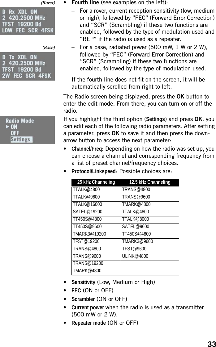
![29[6]Memory information and raw data recording: {percent} No data recording in progress (static icon). Percent-age of free memory in the storage medium used. / {percent}Data recording in progress (dynamic icon). Percent-age of free memory in the storage medium used. Icons appear in succession every 1 second. / ATL data recording in progress[7]Battery: / {percent}A battery has been inserted in the compartment and the energy left in the battery is represented both visually and as a percentage. These two indications are shown successively (percentage appears for 1 second every 5 seconds).The battery is missing (battery compartment empty).Area Icon or Data Reported Meaning[8] The receiver is powered from the AC/DC power sup-ply, not from its battery.[7], (8]The battery is being charged from the external DC source (first icon is animated to show charging).[9]Modem:(Blank) Modem turned off. or Modem turned on:• Blinking: Not initialized yet• Static: Initialized and ready for a connectionThe vertical bars indicate the signal strength at the modem antenna input. The higher the number of bars the better.The antenna symbol shown in the upper left corner stands for “2G”. If the modem detects a 3G network, “3G” is displayed instead.When the signal strength is very weak, four dots appear at the bottom of the icon, instead of vertical bars.Modem on line/connected to the cellular network.[10]WiFi:(Blank) WiFi turned off.WiFi Client active (1 to 3 waves depending on signal level).(1 wave: no signal yet). (Blinking icon: WiFi Ini-tializing.)Data being transmitted over WiFi (2 to 3 waves).[11]Ethernet connection activeData flowing through Ethernet connection(Blank) No Ethernet connectionArea Icon or Data Reported Meaning](https://usermanual.wiki/TRIMBLE-EUROPE/110610.Host-user-manual-1-SP90M-UG-B-Draft2-en-v1b-pdf/User-Guide-3573048-Page-13.png)
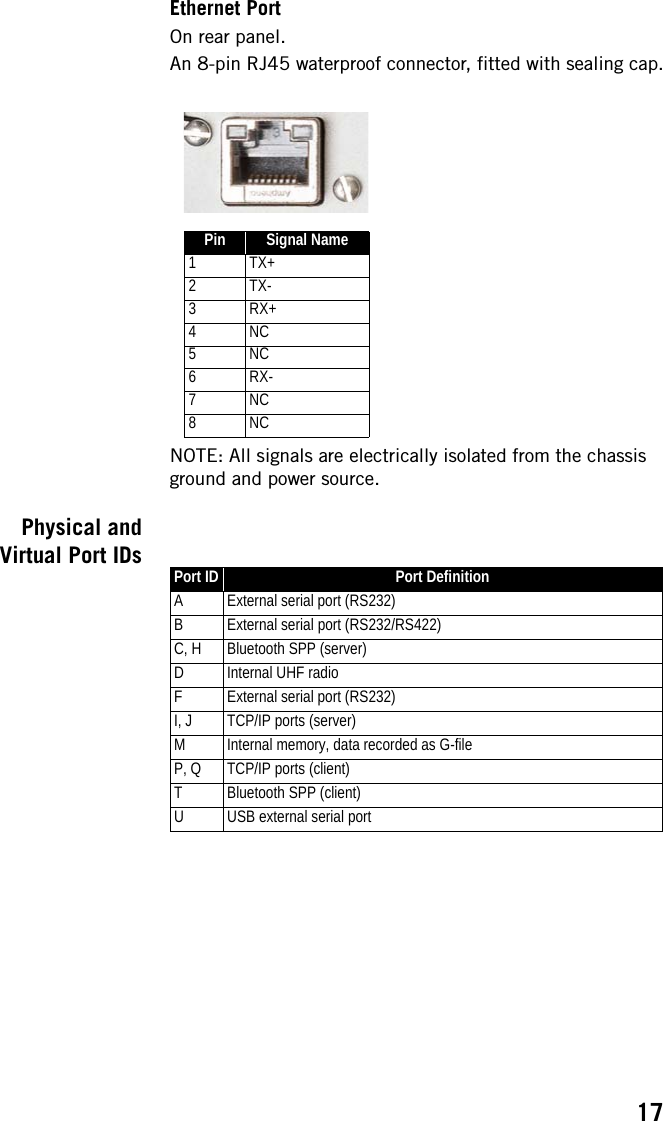
![30[12]Bluetooth, Radio, USB:Bluetooth connection activeInternal radio connected, but not usedInternal radio used respectively as receiver, transmit-ter or repeaterUSB connection active//// Any combination of the five icons is possible. Icons appear in succession every 1 second.(Blank) No Bluetooth or USB connection active, no internal radio installed.[13]WiFi (continued):WiFi Access Point active (Blinking icon: WiFi Initializ-ing).Area Icon or Data Reported Meaning](https://usermanual.wiki/TRIMBLE-EUROPE/110610.Host-user-manual-1-SP90M-UG-B-Draft2-en-v1b-pdf/User-Guide-3573048-Page-14.png)
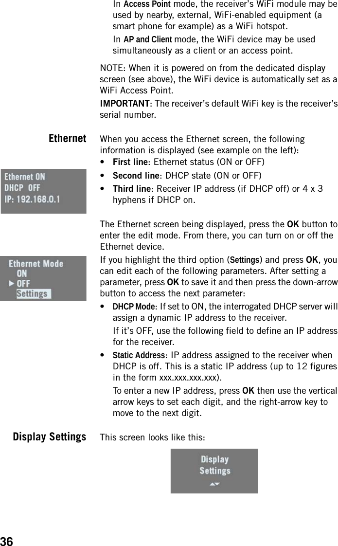
![35receiver. “Manual” means you turn it on or off manually from the GSM screen.•PIN code: Press OK to enter the edit mode.CAUTION: You won’t be able to turn on the GSM modem until you have entered the correct PIN code.•Antenna Mode: Press OK to choose the antenna used by the GSM modem: This can be the built-in antenna (Internal) or an external antenna connected to the rear panel (see [11] on Rear Panel on page 11).WiFi When you access the WiFi screen, the following information is displayed (see examples on the left, first in Access Point mode and second, in client mode):•First line:– “WIFI” label– WiFi mode: “AP” (for Access Point) or “Client”. “AP” is similar to “Hotspot Wifi”•Second line: Receiver’s WiFi name (WiFi SSID), as seen from an external WiFi device in search of a new connection. In client mode, this line displays the SSID of the WiFi device the receiver is connected to.•Third line:– In Access Point mode: Receiver’s static IP address– In Client mode: Connection status: “Connected” (or “Not connected” if the second line is empty).– Signal level (in 20% increments; 100%: +43 dBm)•Fourth line: (client mode only): IP address of WiFi hotspot the receiver is connected to.The WiFi screen being displayed, press the OK button to enter the edit mode. From there, you can turn on or off the WiFi device.If you highlight the third option (Settings) and press OK, you can edit each of the following parameters. After setting a parameter, press OK to save it and then press the down-arrow button to access the next parameter:•Power Mode: Manual or Automatic. “Automatic” means the WiFi module will be powered on when you turn on the receiver. “Manual” means you turn it on or off manually from the WiFi screen.•WIFI Mode: Client, Access Point or AP and Client.In Client mode, the receiver’s WiFi module is set to search for a nearby WiFi network. You need to use the Web Server to find and connect to a WiFi network.](https://usermanual.wiki/TRIMBLE-EUROPE/110610.Host-user-manual-1-SP90M-UG-B-Draft2-en-v1b-pdf/User-Guide-3573048-Page-19.png)