TRIMBLE EUROPE 111256 Zmax Communication Unit User Manual Z Max Net Getting Started Guide
TRIMBLE NANTES S.A.S. Zmax Communication Unit Z Max Net Getting Started Guide
UserManual.wiki
>
TRIMBLE EUROPE
>
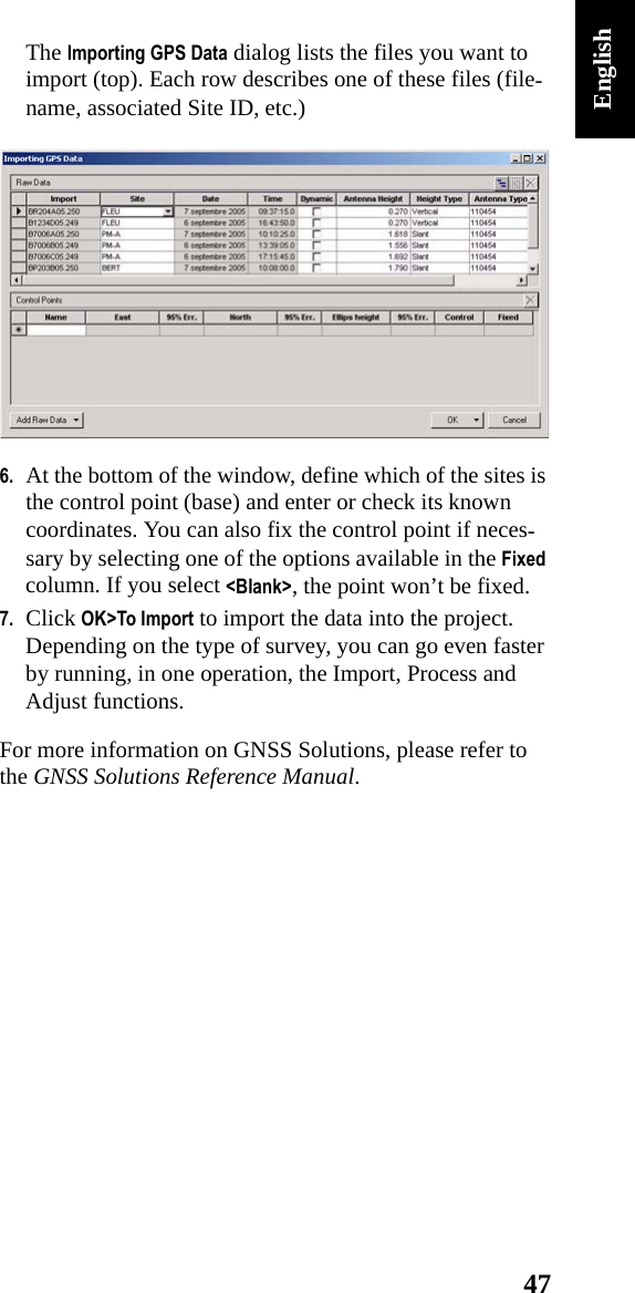
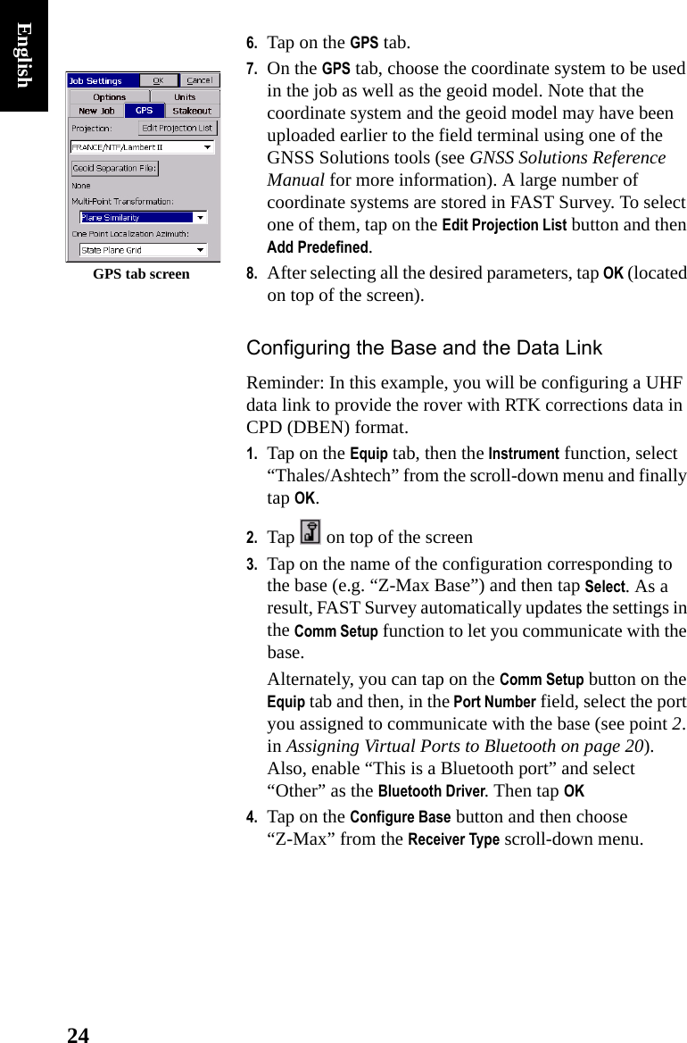
111256 User Manual
user manual
Navigation menu
Upload a User Manual
Namespaces
Wiki Guide
HTML
PDF
Info
Views
User Manual
Discussion / Help
Navigation
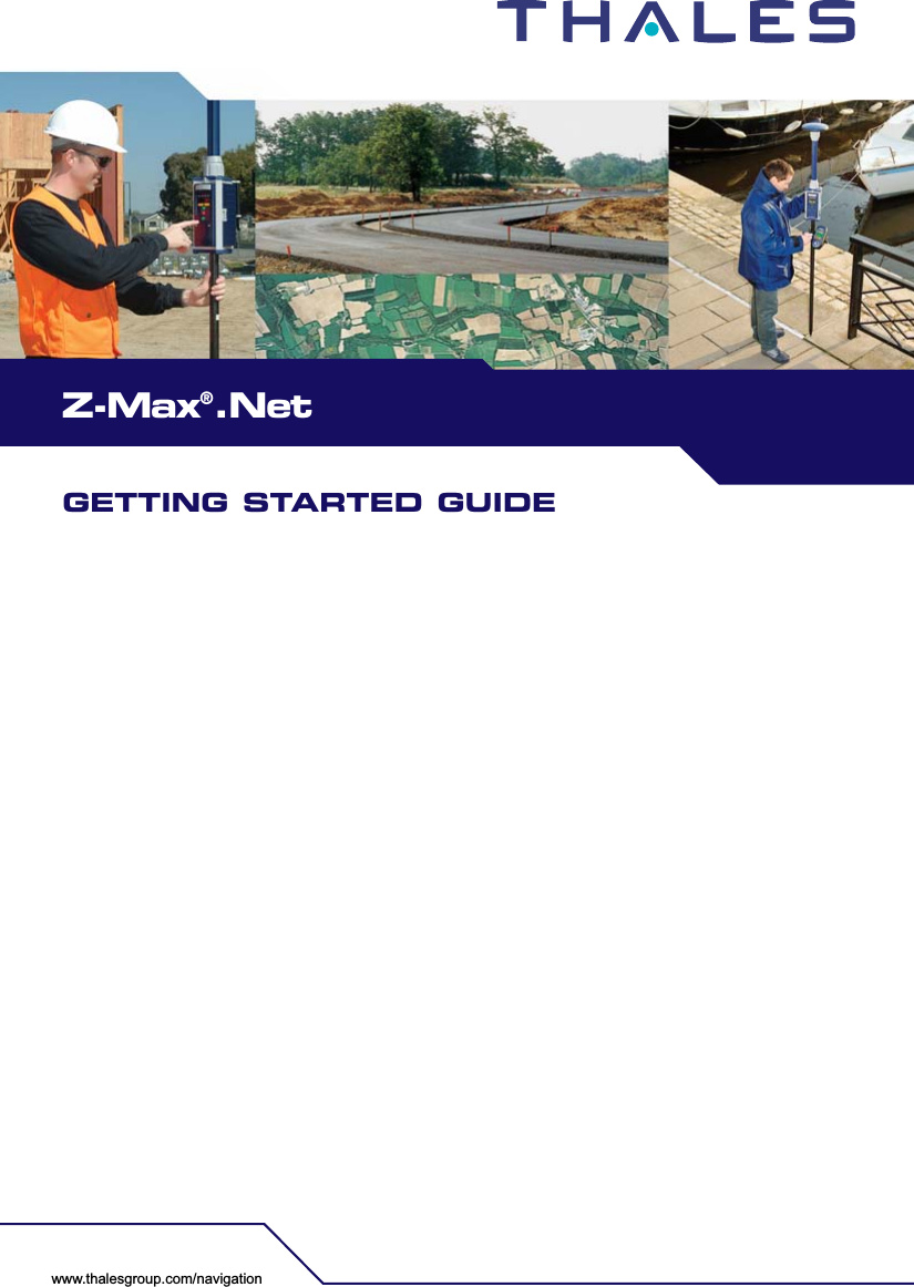
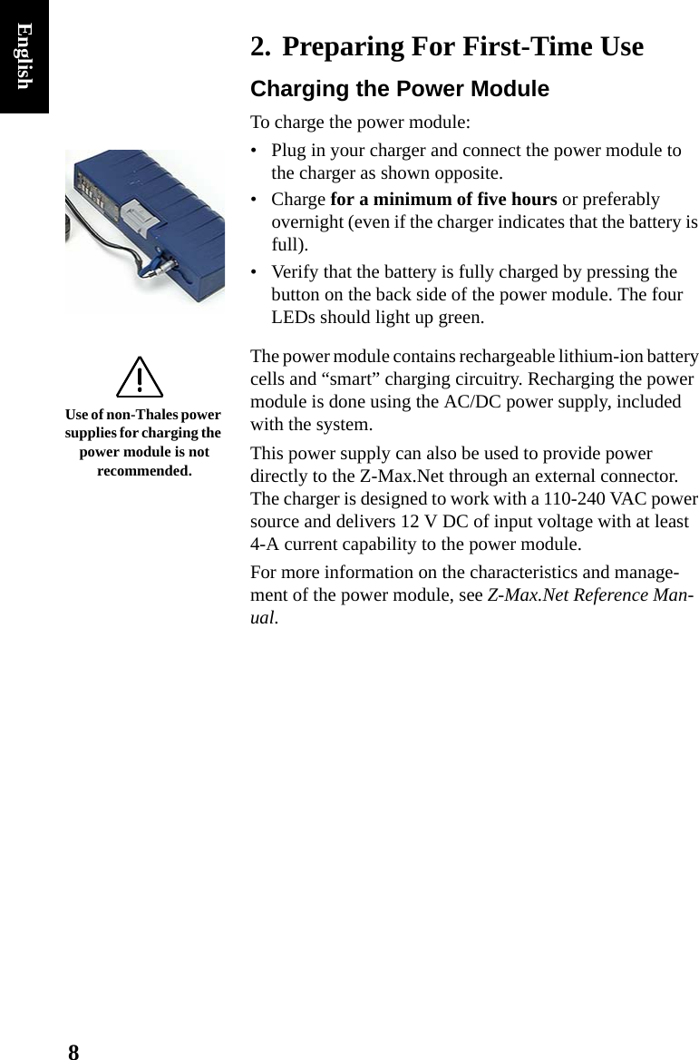
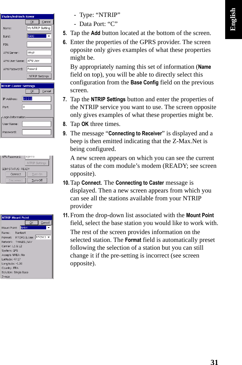
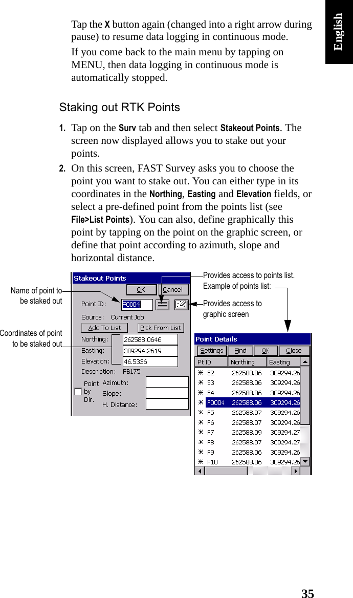
![25English5. Enter the antenna height you measured previously (see point 5. page 15) as well as the method you used for this measurement. If you used the method described on page 15, check Slant.6. Select the type of GPS antenna used, i.e. “[Z-Max GPS] Thales Navigation” as you are using the Z-Max.Net antenna directly connected to the receiver.7. Tap on the Ports tab. With Bluetooth and the Thales radio used, make the following choices:• Type: “THL” (Thales Radio)• Data Port: “C” (Bluetooth connection to field terminal)• Radio Port: “B”• Message Type: “Ashtech CPD”.8. Tap OK to send these parameters to the Z-Max.Net receiver. Re-enter the PIN number. The Z-Max.Net emits a beep. A new menu appears asking you to enter the initialization position for the base.Entering the Base Position and IDUp to six different options are possible to enter this position:](https://usermanual.wiki/TRIMBLE-EUROPE/111256/User-Guide-709542-Page-29.png)
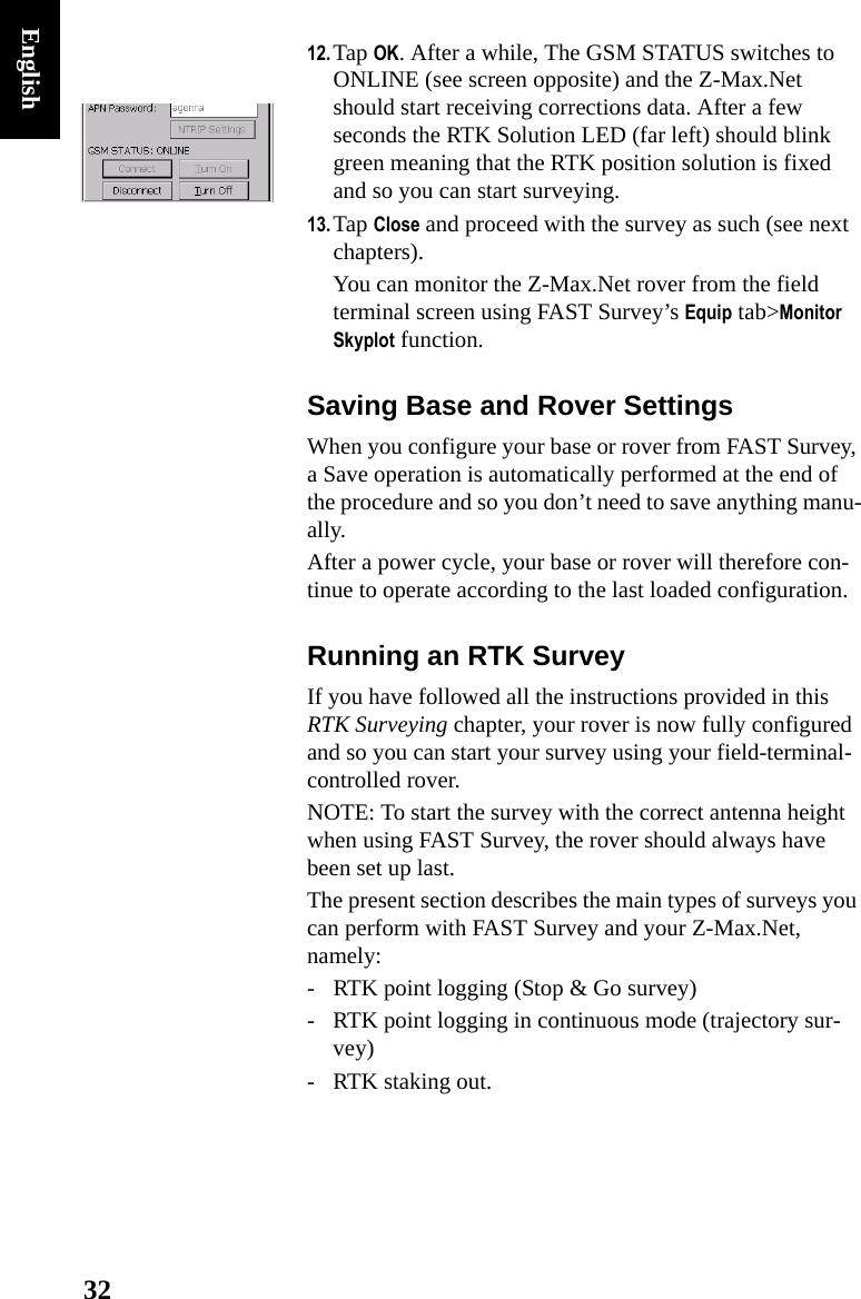
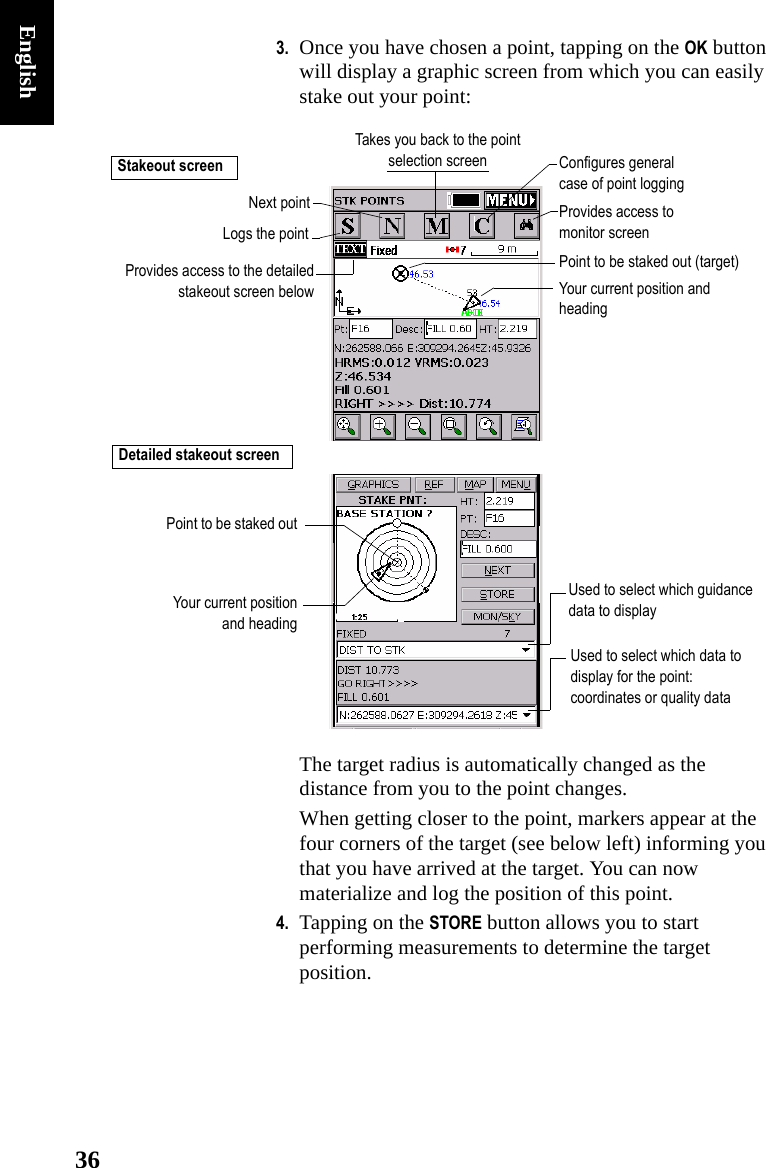
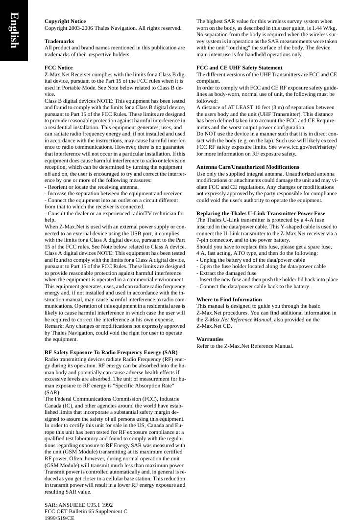
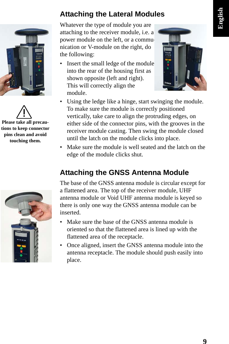
![28EnglishAlternately, you can tap on the Comm Setup button on the Equip tab and then, in the Port Number field, select the port you assigned to communicate with the rover (see point 2. in Assigning Virtual Ports to Bluetooth on page 20). Also, enable “This is a Bluetooth port” and select “Other” as the Bluetooth Driver. Then tap OK.Case #1: Rover Using a UHF Radio Data Link1. Tap on Configure Rover2. In the Rod Hgt field, type in the height mentioned earlier (Hr; see point 3. on page 17) and then check the Vertical option.3. Tap on the Receiver tab and check that the receiver used is “Z-Max”. Also, as you are using a UHF antenna module -although a void one- between the GNSS antenna and the receiver module, select the “[Z-Max GPS UHF] Thales Navigation” antenna in the Antenna Type field.4. Tap on the Ports tab and make the following choices:-Base Config field (at the bottom): “Manual”- Type: “THL” (Thales radio)- Data Port: “C” (Bluetooth connection to field terminal)- Radio Port: “D”- Message Type: “Ashtech (CPD/DSNP LRK)”5. Tap the OK button located on top of the screen. The message “Connecting to Receiver” is displayed and the Z-Max.Net emits a beep meaning that it’s being configured.](https://usermanual.wiki/TRIMBLE-EUROPE/111256/User-Guide-709542-Page-32.png)
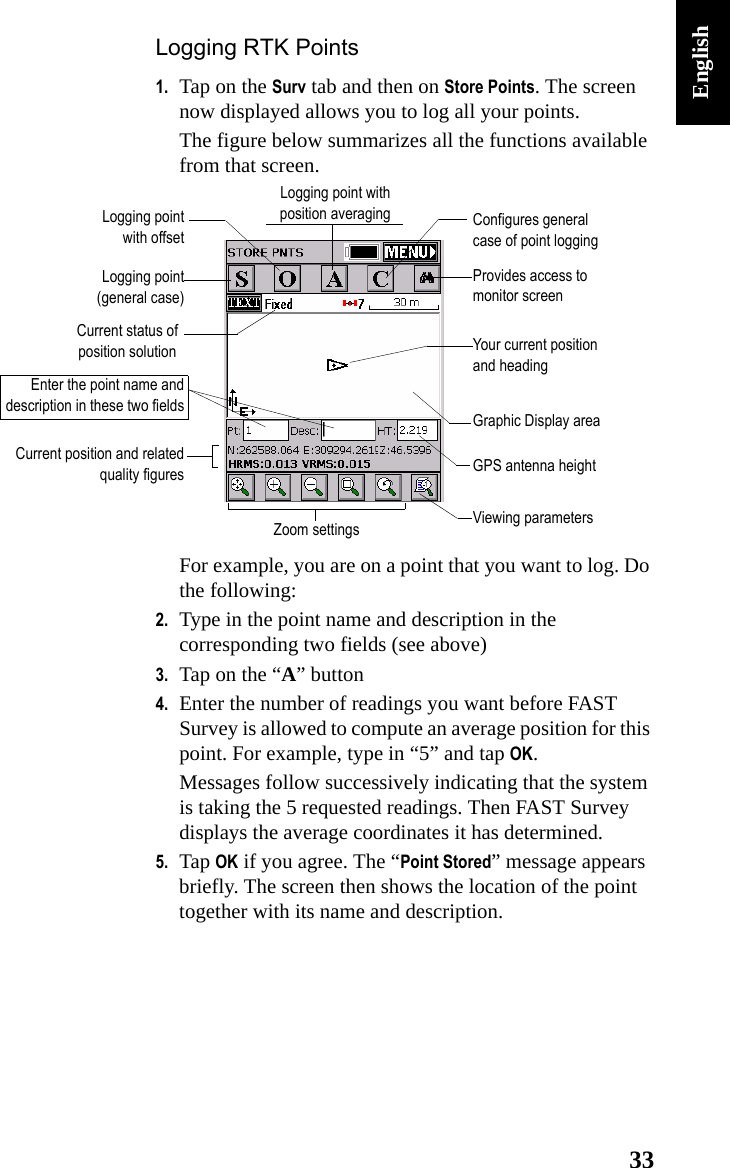
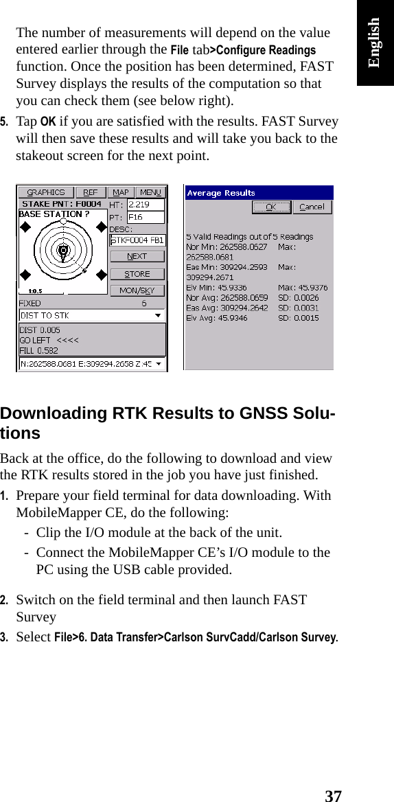
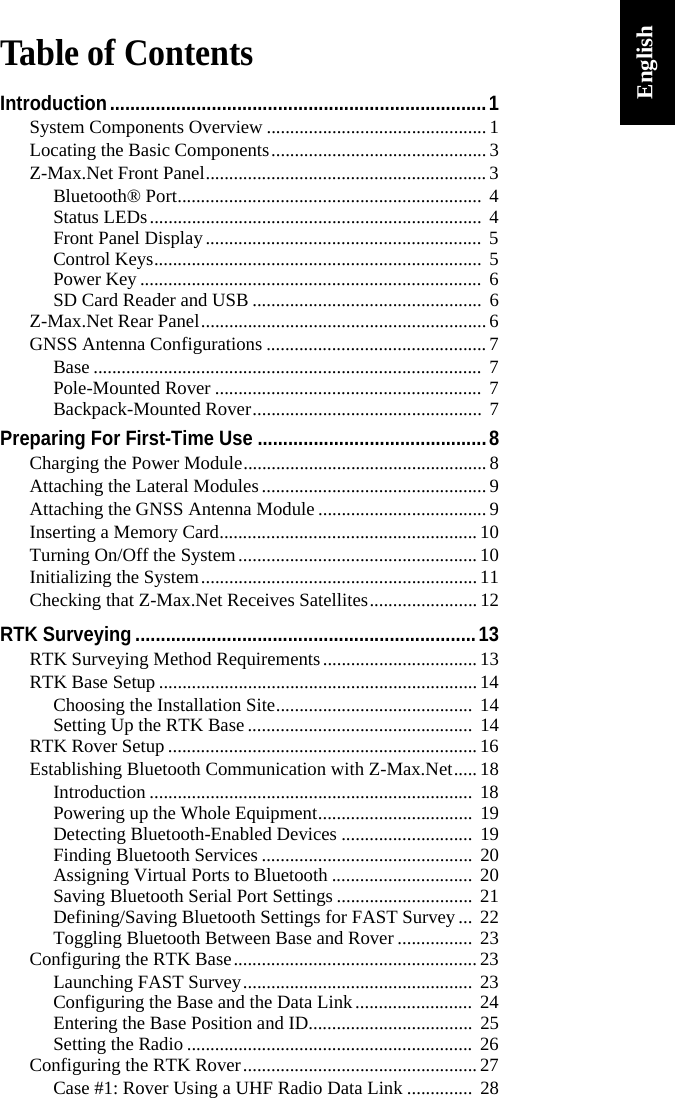
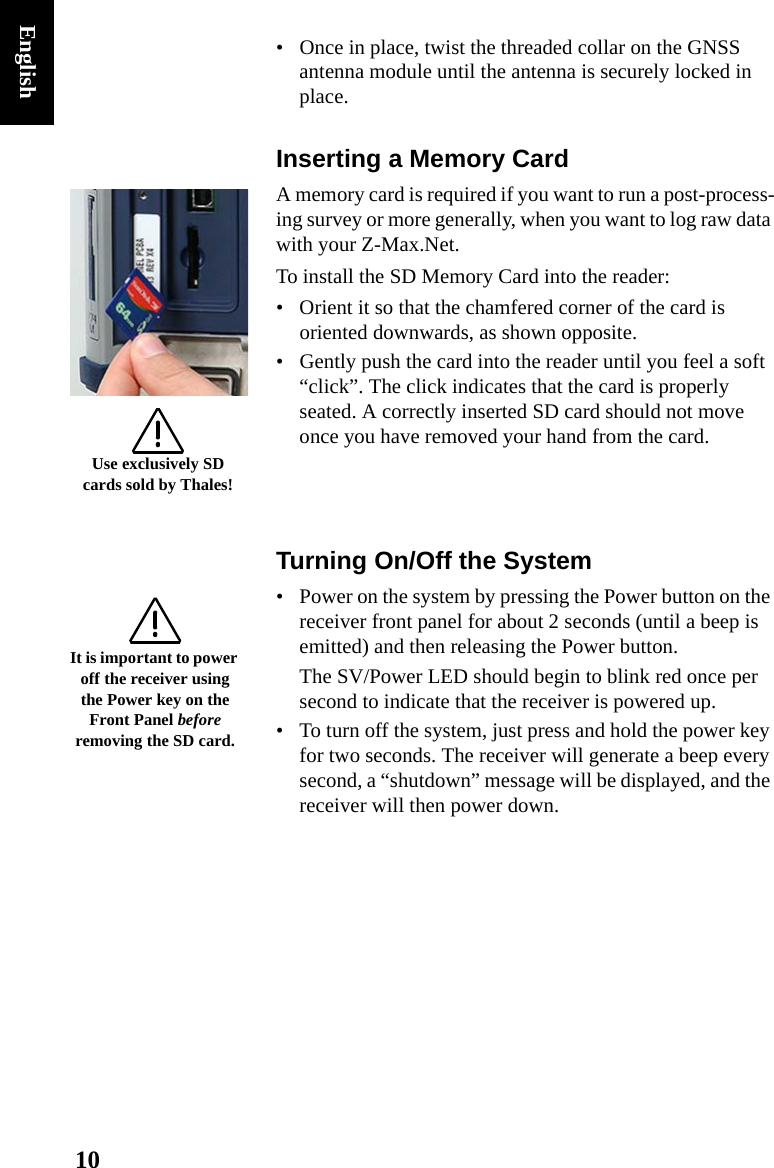
![30EnglishCase #2: Rover Using a GSM/GPRS Data LinkReminder: You do not need to install and run your own base as in this case you will be using RTK corrections data from a provider using the NTRIP protocol. This means you just have to set up and use your rover. Below is the key information you need to know in this case of use:• A GPRS data link is used to receive RTK corrections data from an NTRIP caster. The GPRS provider is assumed to have delivered the following information so you can start your modem:• The NTRIP service provider is assumed to have delivered the following information so you can access the NTRIP service:Follow the instructions below to set up the rover:1. Tap on Configure Rover2. In the Rod Hgt field, type in the height mentioned earlier (Hr; see point 3. on page 17) and then check the Vertical option.3. Tap on the Receiver tab and check that the receiver used is the Z-Max.Net. Also, select the “[Z-Max GPS UHF] Thales Navigation” antenna in the Antenna Type field.4. Tap on the Ports tab and make the following choices:-Base Config field (at the bottom): “Manual”Modem SIM PIN number (if any)Access Point NameLog in for GPRS connectionPassword for GPRS connectionCaster IP address (xxx.xxx.xxx.xxx)IP port numberLog in for access to NTRIP casterPassword for access to NTRIP caster](https://usermanual.wiki/TRIMBLE-EUROPE/111256/User-Guide-709542-Page-34.png)