TRIMBLE EUROPE 111256 Zmax Communication Unit User Manual Z Max Net Getting Started Guide
TRIMBLE NANTES S.A.S. Zmax Communication Unit Z Max Net Getting Started Guide
user manual

GETTING STARTED GUIDE
Z-Max
®
.Net
www.thalesgroup.com/navigation

English
Copyright Notice
Copyright 2003-2006 Thales Navigation. All rights reserved.
Trademarks
All product and brand names mentioned in this publication are
trademarks of their respective holders.
FCC Notice
Z-Max.Net Receiver complies with the limits for a Class B dig-
ital device, pursuant to the Part 15 of the FCC rules when it is
used in Portable Mode. See Note below related to Class B de-
vice.
Class B digital devices NOTE: This equipment has been tested
and found to comply with the limits for a Class B digital device,
pursuant to Part 15 of the FCC Rules. These limits are designed
to provide reasonable protection against harmful interference in
a residential installation. This equipment generates, uses, and
can radiate radio frequency energy and, if not installed and used
in accordance with the instructions, may cause harmful interfer-
ence to radio communications. However, there is no guarantee
that interference will not occur in a particular installation. If this
equipment does cause harmful interference to radio or television
reception, which can be determined by turning the equipment
off and on, the user is encouraged to try and correct the interfer-
ence by one or more of the following measures:
- Reorient or locate the receiving antenna.
- Increase the separation between the equipment and receiver.
- Connect the equipment into an outlet on a circuit different
from that to which the receiver is connected.
- Consult the dealer or an experienced radio/TV technician for
help.
When Z-Max.Net is used with an external power supply or con-
nected to an external device using the USB port, it complies
with the limits for a Class A digital device, pursuant to the Part
15 of the FCC rules. See Note below related to Class A device.
Class A digital devices NOTE: This equipment has been tested
and found to comply with the limits for a Class A digital device,
pursuant to Part 15 of the FCC Rules. These limits are designed
to provide reasonable protection against harmful interference
when the equipment is operated in a commercial environment.
This equipment generates, uses, and can radiate radio frequency
energy and, if not installed and used in accordance with the in-
struction manual, may cause harmful interference to radio com-
munications. Operation of this equipment in a residential area is
likely to cause harmful interference in which case the user will
be required to correct the interference at his own expense.
Remark: Any changes or modifications not expressly approved
by Thales Navigation, could void the right for user to operate
the equipment.
RF Safety Exposure To Radio Frequency Energy (SAR)
Radio transmitting devices radiate Radio Frequency (RF) ener-
gy during its operation. RF energy can be absorbed into the hu-
man body and potentially can cause adverse health effects if
excessive levels are absorbed. The unit of measurement for hu-
man exposure to RF energy is "Specific Absorption Rate"
(SAR).
The Federal Communications Commission (FCC), Industrie
Canada (IC), and other agencies around the world have estab-
lished limits that incorporate a substantial safety margin de-
signed to assure the safety of all persons using this equipment.
In order to certify this unit for sale in the US, Canada and Eu-
rope this unit has been tested for RF exposure compliance at a
qualified test laboratory and found to comply with the regula-
tions regarding exposure to RF Energy.SAR was measured with
the unit (GSM Module) transmitting at its maximum certified
RF power. Often, however, during normal operation the unit
(GSM Module) will transmit much less than maximum power.
Transmit power is controlled automatically and, in general is re-
duced as you get closer to a cellular base station. This reduction
in transmit power will result in a lower RF energy exposure and
resulting SAR value.
SAR: ANSI/IEEE C95.1 1992
FCC OET Bulletin 65 Supplement C
1999/519/CE
The highest SAR value for this wireless survey system when
worn on the body, as described in this user guide, is 1.44 W/kg.
No separation from the body is required when the wireless sur-
vey system is in operation as the SAR measurements were taken
with the unit "touching" the surface of the body. The device
main intent use is for handheld operations only.
FCC and CE UHF Safety Statement
The different versions of the UHF Transmitters are FCC and CE
compliant.
In order to comply with FCC and CE RF exposure safety guide-
lines as body-worn, normal use of unit, the following must be
followed:
A distance of AT LEAST 10 feet (3 m) of separation between
the users body and the unit (UHF Transmitter). This distance
has been defined taken into account the FCC and CE Require-
ments and the worst output power configuration.
Do NOT use the device in a manner such that it is in direct con-
tact with the body (e.g. on the lap). Such use will likely exceed
FCC RF safety exposure limits. See www.fcc.gov/oet/rfsafety/
for more information on RF exposure safety.
Antenna Care/Unauthorized Modifications
Use only the supplied integral antenna. Unauthorized antenna
modifications or attachments could damage the unit and may vi-
olate FCC and CE regulations. Any changes or modifications
not expressly approved by the party responsible for compliance
could void the user's authority to operate the equipment.
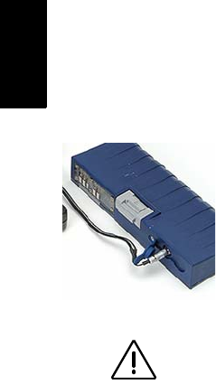
Replacing the Thales U-Link Transmitter Power Fuse
The Thales U-Link transmitter is protected by a 4-A fuse
inserted in the data/power cable. This Y-shaped cable is used to
connect the U-Link transmitter to the Z-Max.Net receiver via a
7-pin connector, and to the power battery.
Should you have to replace this fuse, please get a spare fuse,
4 A, fast acting, ATO type, and then do the following:
- Unplug the battery end of the data/power cable
- Open the fuse holder located along the data/power cable
- Extract the damaged fuse
- Insert the new fuse and then push the holder lid back into place
- Connect the data/power cable back to the battery.
Where to Find Information
This manual is designed to guide you through the basic
Z-Max.Net procedures. You can find additional information in
the Z-Max.Net Reference Manual, also provided on the
Z-Max.Net CD.
Warranties
Refer to the Z-Max.Net Reference Manual.

English
Table of Contents
Introduction..........................................................................1
System Components Overview ............................................... 1
Locating the Basic Components.............................................. 3
Z-Max.Net Front Panel............................................................ 3
Bluetooth® Port................................................................. 4
Status LEDs....................................................................... 4
Front Panel Display........................................................... 5
Control Keys...................................................................... 5
Power Key ......................................................................... 6
SD Card Reader and USB ................................................. 6
Z-Max.Net Rear Panel.............................................................6
GNSS Antenna Configurations ...............................................7
Base ................................................................................... 7
Pole-Mounted Rover ......................................................... 7
Backpack-Mounted Rover................................................. 7
Preparing For First-Time Use .............................................8
Charging the Power Module.................................................... 8
Attaching the Lateral Modules ................................................ 9
Attaching the GNSS Antenna Module .................................... 9
Inserting a Memory Card.......................................................10
Turning On/Off the System................................................... 10
Initializing the System........................................................... 11
Checking that Z-Max.Net Receives Satellites....................... 12
RTK Surveying ...................................................................13
RTK Surveying Method Requirements................................. 13
RTK Base Setup ....................................................................14
Choosing the Installation Site.......................................... 14
Setting Up the RTK Base................................................ 14
RTK Rover Setup .................................................................. 16
Establishing Bluetooth Communication with Z-Max.Net..... 18
Introduction ..................................................................... 18
Powering up the Whole Equipment................................. 19
Detecting Bluetooth-Enabled Devices ............................ 19
Finding Bluetooth Services ............................................. 20
Assigning Virtual Ports to Bluetooth .............................. 20
Saving Bluetooth Serial Port Settings ............................. 21
Defining/Saving Bluetooth Settings for FAST Survey ... 22
Toggling Bluetooth Between Base and Rover ................ 23
Configuring the RTK Base.................................................... 23
Launching FAST Survey................................................. 23
Configuring the Base and the Data Link ......................... 24
Entering the Base Position and ID................................... 25
Setting the Radio ............................................................. 26
Configuring the RTK Rover.................................................. 27
Case #1: Rover Using a UHF Radio Data Link .............. 28

English
Case #2: Rover Using a GSM/GPRS Data Link............. 30
Saving Base and Rover Settings ........................................... 32
Running an RTK Survey....................................................... 32
Logging RTK Points ....................................................... 33
Logging RTK Points in Continuous Mode ..................... 34
Staking out RTK Points .................................................. 35
Downloading RTK Results to GNSS Solutions.................... 37
Post-processing Surveying...............................................39
Reminder on the Static Surveying Method ........................... 39
Running a Static Survey........................................................ 40
Equipment Setup............................................................. 40
Getting the Z-Max.Net Unit Started in Static ................. 41
Starting Data Collection.................................................. 43
End of Data Collection.................................................... 43
Downloading Field Data to your PC..................................... 45
Post-Processing Field Data ................................................... 46
Front Panel Interface Function Diagram..........................48

1
English
1. Introduction
Congratulations! You have just acquired your new dual-
frequency Z-Max™.Net GNSS Surveying System from
Thales!
GNSS (or Global Navigation Satellite System) has
revolutionized control surveys, topographic data collection
and construction surveying. Purchasing the right tools for a
professional job is essential in today's competitive business
environment.
Learning to put these tools to work quickly and efficiently
will be the focus of the present guide.
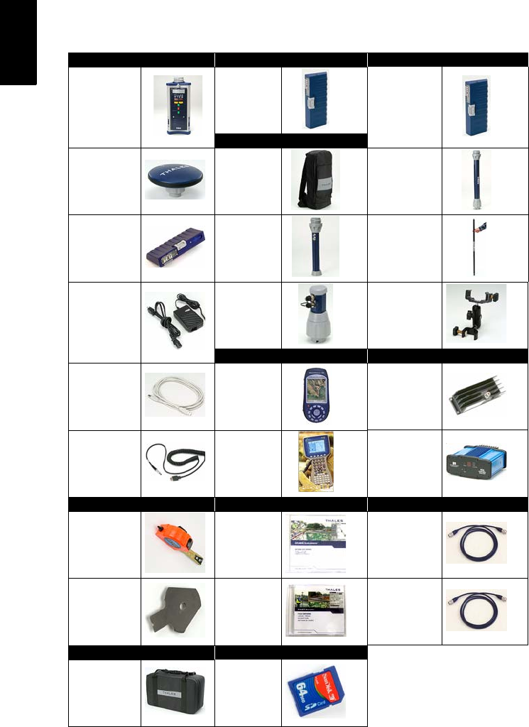
System Components Overview
The table below provides an overview of the different key
items composing the Z-Max.Net System. Depending on
your purchase, based on the type of survey you wish to
perform, you may only have part of the listed items. Please
refer to the delivered packing list for an accurate description
of the equipment that has been delivered to you.
Conversely, as this table is just an overview, it does not list
all the possible items and accessories. For example, the list
of all the possible field terminals is provided but we
intentionally do not mention the field brackets that usually
come along with them. For more information on these items,
please contact your dealer.
For ordering information, please refer to the Z-Max.Net
Reference Manual.
2
English
Basic Post-Processing Rover, RTK
GPS Receiver
Module
V-Module (1)
(Void module) Communication
Module
Rover, Backpack
GNSS Antenna
Module Backpack UHF Antenna
Module (2)
Power Module Range Pole
RF Adapter Range Pole
Charger Max RF
Adapter
Mounting
Bracket
Field Terminal Radio
USB Cable
Thales
MobileMap-
per CE
Thales U-Link
transmitter
Serial Data
Cable
Juniper
Allegro CX
Pacific-Crest
UHF Transmitter
Static, Base Software RF Cables
HI measure-
ment tool
GNSS Solu-
tions CD GPS-RF cable
eHI Measure-
ment Plate
FAST Survey
CD UHF-RF cable
Transport Case Memory Device
(1) Also used in an RTK base using a
UHF radio as the data link.
(2) A void UHF antenna module also
exists.
Soft case SD Card (sold
by Thales)
3
English
Locating the Basic Components
As you are facing the front panel of the GPS receiver
module, the power module attaches to the left-hand side of
the receiver module and the communication module (or V-
module) to the right-hand side.
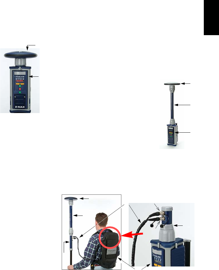
Z-Max.Net Front Panel
2. GNSS Antenna Module
3. Power Module 4. Communication Module
or V-Module
1. Receiver
Module
Status LEDs
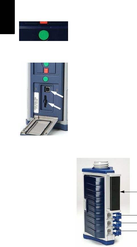
Front Panel User Interface
Power key
Control keys
Z-Max.Net Bluetooth®
4
English
Bluetooth® Port
This device allows you to communicate with the Z-Max.Net
through a Bluetooth wireless connection. This port is
identified as “port C” on the Z-Max.Net.
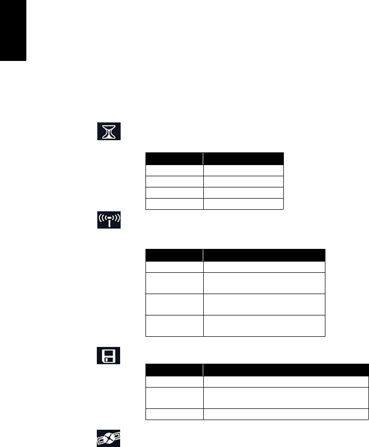
Status LEDs
From left to right, the LEDs are:
•RTK Solution. This LED is only operational when the
receiver is configured as an RTK rover.
•Communication. This LED indicates when real-time
data is transmitted (base) or received (rover).
•Data Log. This LED shows the data logging status.
•Satellite/Power. After power up, this LED will continue
to blink red once every 1-2 seconds to indicate that the
unit is powered on. Between each red blink, the LED will
also blink green once for each satellite that the receiver is
tracking.
Color Meaning
Off Not a RTK rover
Blinking green Fixed solution
Blinking orange Float solution
Blinking red No RTK solution
Color Meaning
Off No data link has been configured
Blinking green Base: Transmits data
Rover: Base data received and used
Blinking red Base: Irrelevant
Rover: Base data received but not used
Not blinking Base: No data transmitted
Rover: No base data received
Color Meaning
Off No data logging in progress
Blinking green Data logging in progress. Blinks at the frequency of the
recording interval setting (20 seconds by default).
Red Unable to log data (memory full)
5
English
Front Panel Display
The front panel display is an 8-character, alphanumeric LED
display that is used to monitor receiver status, set receiver
parameters and configure the receiver to perform different
types of surveys.
The screen displays up to eight characters at one time.
Messages or parameters longer than eight characters are
scrolled from right to left.
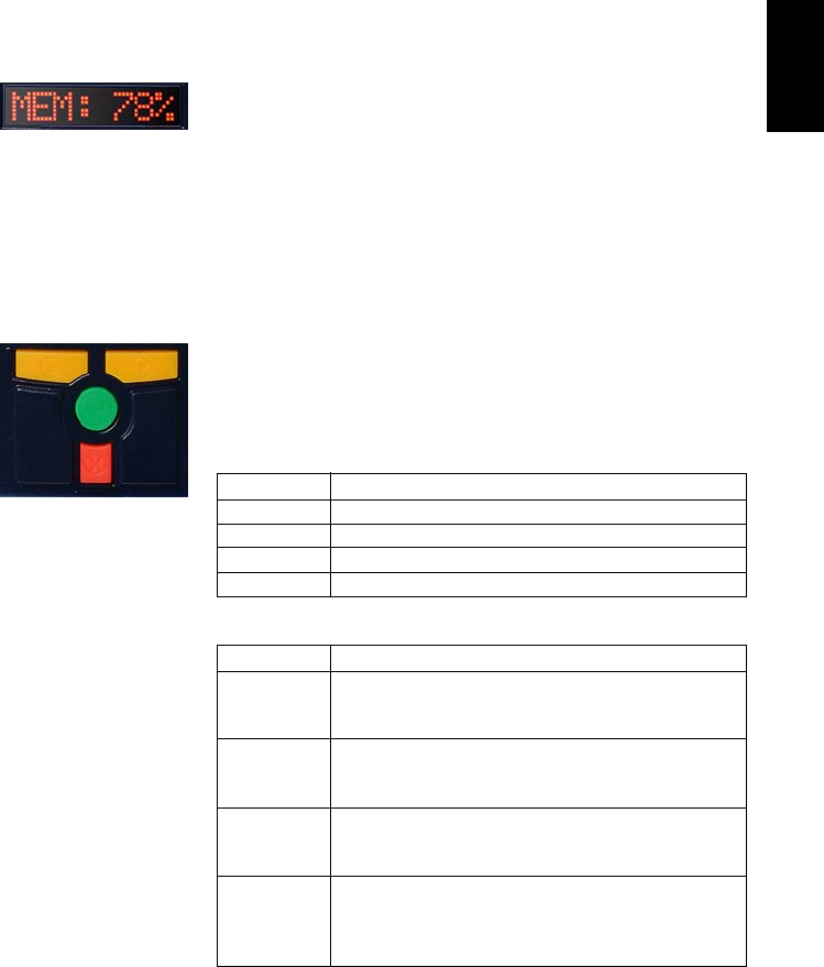
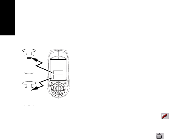
Control Keys
The four control keys are used in conjunction with the front
panel display. They will work differently depending on
whether the screen is in Display or Edit mode.
Display Mode:
Edit Mode:
See Z-Max.Net Reference Manual for more information.
Key Operation
UP (yellow) Scrolls menu (at same level) forward
DOWN (yellow) Scrolls menu (at same level) backward
ENTER (green) Selects and moves down to next level or enters Edit mode
CANCEL (red) Returns to upper level
Key Operation
UP (yellow)
Data entry context: Scrolls forward through characters
Parameter list context: Scrolls forward
Fast scrolling if held depressed for 3 seconds
DOWN (yellow)
Data entry context: Scrolls backward through characters
Parameter list context: Scrolls backward
Fast scrolling if held depressed for 3 seconds
ENTER (green)
Parameter list context: Selects parameter
Data entry context: Accepts character and moves to next space
or quits Edit mode
CANCEL (red)
Data entry context: Deletes last edited character, stays in Edit
mode
Parameter list context: Moves from Edit mode to Display mode
without selecting the parameter.
Down key
Enter key
Cancel key
Up key
6
English
Power Key
This key is used to power up, power down or initialize the
unit (see page 10).
SD Card Reader and USB
Below the four control keys is a small door fastened by two
thumbscrews. Unscrew the attaching screws and open the
door to reveal the SD Card slot and the USB port.
The SD card slot holds the SD card that serves as the
receiver's data storage memory. All data recorded by the unit
is stored on the SD card. Warning! Use exclusively SD
cards sold by Thales.
The USB port is one of the external ports available for
connecting to a computer. The USB port is a type-B
connector.
Z-Max.Net Rear Panel
For connector pinout, see Z-Max.Net Reference Manual.
Power key
Handle
Port A (RS232)
Port B (RS232 or RS422)
External Power In (10-28 V DC)
7
English
GNSS Antenna Configurations
In all cases of use, the GNSS antenna module must be
connected to the receiver module. But there are three
different ways of doing this, as explained below.
Base
The GNSS antenna module (A) is directly attached to the
receiver module (B).
Pole-Mounted Rover
The GNSS antenna module (A) is attached
to the receiver module (B) via a UHF
antenna module or a Void UHF antenna
module (C).
Backpack-Mounted Rover
The GNSS antenna module (A) is attached to the receiver
module (B) via a UHF antenna module or Void UHF antenna
module (C), a range pole adapter (D), a dual RF cable (E)
and a Max-RF adapter (F).
(A)
(B)
(C)
(A)
(B)
(D)
(C)
(F)
(E)
(A)
(B)
GPS
UHF
8
English
2. Preparing For First-Time Use
Charging the Power Module
To charge the power module:
• Plug in your charger and connect the power module to
the charger as shown opposite.
•Charge for a minimum of five hours or preferably
overnight (even if the charger indicates that the battery is
full).
• Verify that the battery is fully charged by pressing the
button on the back side of the power module. The four
LEDs should light up green.
The power module contains rechargeable lithium-ion battery
cells and “smart” charging circuitry. Recharging the power
module is done using the AC/DC power supply, included
with the system.
This power supply can also be used to provide power
directly to the Z-Max.Net through an external connector.
The charger is designed to work with a 110-240 VAC power
source and delivers 12 V DC of input voltage with at least
4-A current capability to the power module.
For more information on the characteristics and manage-
ment of the power module, see Z-Max.Net Reference Man-
ual.
Use of non-Thales power
supplies for charging the
power module is not
recommended.
9
English
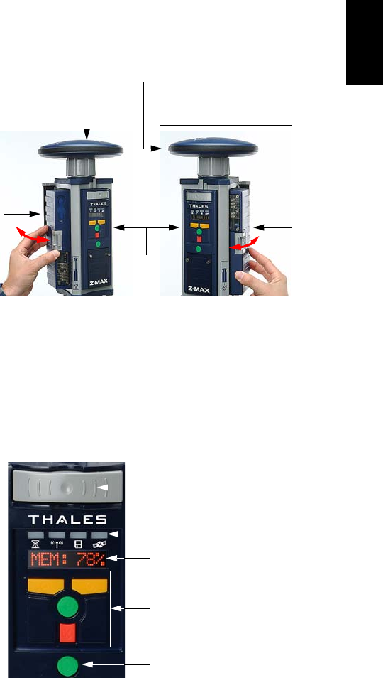
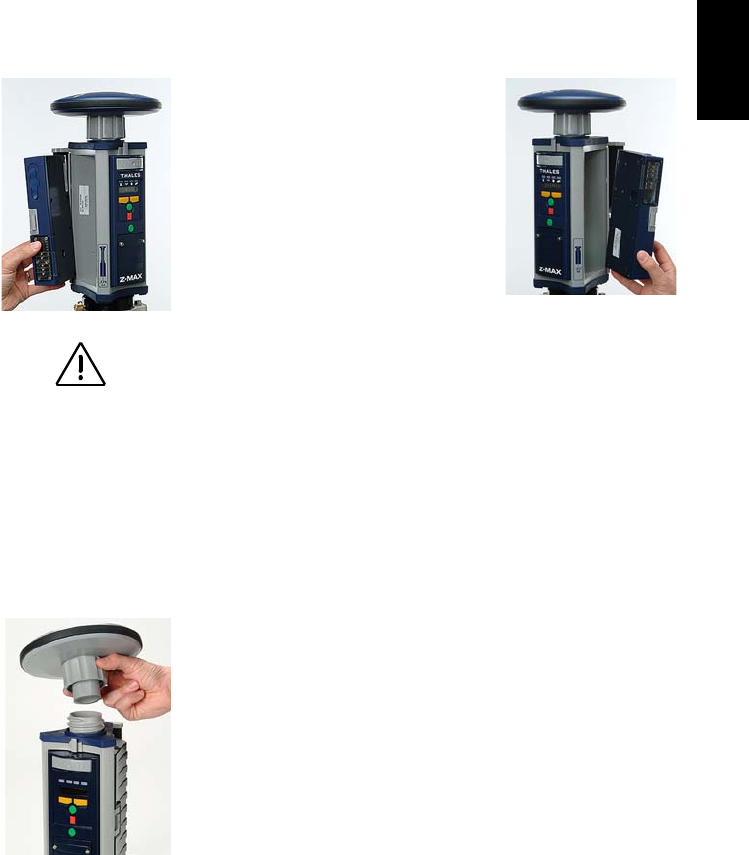
Attaching the Lateral Modules
Whatever the type of module you are
attaching to the receiver module, i.e. a
power module on the left, or a commu-
nication or V-module on the right, do
the following:
• Insert the small ledge of the module
into the rear of the housing first as
shown opposite (left and right).
This will correctly align the
module.
• Using the ledge like a hinge, start swinging the module.
To make sure the module is correctly positioned
vertically, take care to align the protruding edges, on
either side of the connector pins, with the grooves in the
receiver module casting. Then swing the module closed
until the latch on the module clicks into place.
• Make sure the module is well seated and the latch on the
edge of the module clicks shut.
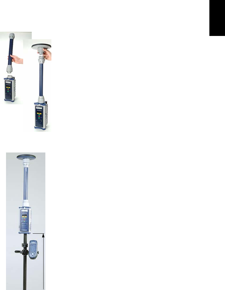
Attaching the GNSS Antenna Module
The base of the GNSS antenna module is circular except for
a flattened area. The top of the receiver module, UHF
antenna module or Void UHF antenna module is keyed so
there is only one way the GNSS antenna module can be
inserted.
• Make sure the base of the GNSS antenna module is
oriented so that the flattened area is lined up with the
flattened area of the receptacle.
• Once aligned, insert the GNSS antenna module into the
antenna receptacle. The module should push easily into
place.
Please take all precau-
tions to keep connector
pins clean and avoid
touching them.
10
English
• Once in place, twist the threaded collar on the GNSS
antenna module until the antenna is securely locked in
place.
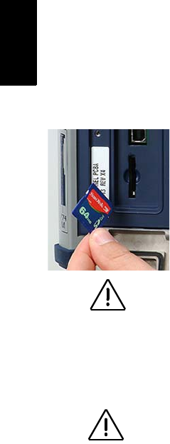
Inserting a Memory Card
A memory card is required if you want to run a post-process-
ing survey or more generally, when you want to log raw data
with your Z-Max.Net.
To install the SD Memory Card into the reader:
• Orient it so that the chamfered corner of the card is
oriented downwards, as shown opposite.
• Gently push the card into the reader until you feel a soft
“click”. The click indicates that the card is properly
seated. A correctly inserted SD card should not move
once you have removed your hand from the card.
Turning On/Off the System
• Power on the system by pressing the Power button on the
receiver front panel for about 2 seconds (until a beep is
emitted) and then releasing the Power button.
The SV/Power LED should begin to blink red once per
second to indicate that the receiver is powered up.
• To turn off the system, just press and hold the power key
for two seconds. The receiver will generate a beep every
second, a “shutdown” message will be displayed, and the
receiver will then power down.
Use exclusively SD
cards sold by Thales!
It is important to power
off the receiver using
the Power key on the
Front Panel before
removing the SD card.

11
English
Initializing the System
Initializing the system is recommended the first time you use
your system to:
• Clear the internal memory
• Reset the user settings to their default values
• Clear ephemeris and almanac information in memory
• Re-format the SD card. Note that initialization should
also be performed every time you prepare your SD card
for a new survey project. It’s always better to delete files
from the SD Card by running an initialization sequence
rather than using any other method.
Initializing the system is also appropriate any time the
Z-Max.Net does not work as expected.
To initialize the system from the Power button, assuming the
system is off, do the following:
• Press the Power button for at least 5 seconds.
The display will show “re-init”, indicating that the
receiver is in the initialization process.
The initialization process will take several minutes
depending on the size of the SD card. The front panel
will continue to display “re-init” until the process is com-
plete.
When complete, the receiver will be powered on and in
the normal state with the front panel displaying
“SYSINFO” and the SD card ready to use.
12
English
Checking that Z-Max.Net Receives
Satellites
If the GPS antenna has a reasonably good view to the sky,
within a few minutes, the receiver should begin to track sat-
ellites. This is indicated by the SV/Power LED:
1. It should blink red once per second to indicate that power
is on, and blink green several times between each red
blink.
2. It will blink green once for each satellite that is being
tracked. In normal conditions of reception, the system
should receive about eight satellites on average.
Please go outside after
initialization and make
sure your system has a
clear view of the sky in
all directions.
13
English
3. RTK Surveying
RTK Surveying Method Requirements
Key information is provided below.
1. Two units are needed: one (the base) is operated on an accurately known
position while the other (the rover) is used in the working area.
2. A data link must be established from the base to the rover. This data link
can be implemented in three different ways:
- UHF radio
- Cellular modem (GSM)
- Other external device
3. Depending on the chosen data link, the base will be either:
- A “real” base system (with UHF radio, GSM, or other external device)
- Or a “virtual” base system that delivers its data via a cellular modem
(GPRS).
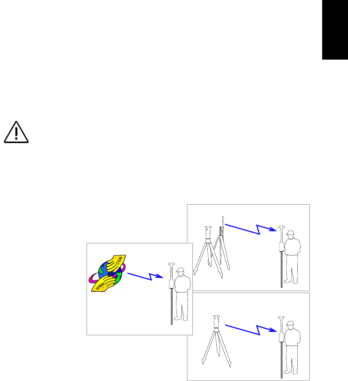
The main Z-Max.Net RTK system configurations are illustrated below:
4. Two different rover setups can be used, backpack or range pole, yet
operated similarly. Only the pole-mounted rover system will be described
in this Guide. For more information on the backpack mounting, refer to the
Z-Max.Net Reference Manual.
5. RTK is easier to operate using a field terminal running FAST Survey. RTK
can also be operated from the receiver front panel display.
6. Whatever the base used (“real” or “virtual”), its distance to the rover, called
“baseline” (up to 50 km or 30 miles), must roughly be known to make sure
RTK results will achieve the expected level of accuracy.
When the base setup is
under your responsibil-
ity, make sure the base
is sited in a clear area
giving the best possible
view of the sky!
When this is possible,
avoid trees, buildings or
any high obstacles in the
vicinity of the base.
Having a clear view of
the sky will allow the
base to collect data from
a maximum of visible
satellites, which is highly
recommended to perform
a successful, accurate
and fast survey.
Base
UHF Radio
Rover
Data Link
Rover
Base Rover
GSM
GPRS
Data Link
Data Link
Internet

14
English
RTK Base Setup
A typical base setup is described in this section in which:
• A conventional tripod is used
• A Thales U-Link radio is used for the data link
• RTK corrections data are transmitted in Ashtech CPD
(DBEN) format
• An external 12-V DC battery is used for powering both
the Z-Max.Net base and the U-Link transmitter
• A Bluetooth-enabled field terminal (MobileMapper CE)
is used, running the FAST Survey software, to set up the
base.
For other base configurations, it’s easy to extrapolate from
the instructions given below, knowing that configuring a
base always implies: 1) entering its geographical location
and 2) defining the data link.
Choosing the Installation Site
The installation site should offer the best possible GPS
reception conditions. The GNSS antenna should have a
clear view of the sky in all directions. There should be no,
or a minimum of satellite obstructions in the vicinity.
Setting Up the RTK Base
1. Connect the system components (power module, GNSS
antenna and V-module) as explained on page 9.
Because a UHF radio transmitter is used for the data link,
a V-module, and not a communication module, can be
attached to the right side of the receiver module.
2. Center and level the tripod over the ground mark.
15
English
3. Insert the brass tribrach adapter through the hole in the
HI measurement plate and screw the adapter/plate into
the 5/8” threaded receptacle in the bottom of the
Z-Max.Net receiver module.
4. Carefully place the Z-Max.Net assembly into the tribrach
mounted on the tripod over the point.
5. Use the tape to measure from the reference point on the
ground to the measurement point of the Z-Max.Net (see
Hb opposite). Later on, you will have to enter the value
read on the tape (see point 5. on page 25).
6. Using the power cable supplied (P/N
730477), connect the Z-Max.Net power
input (marked “PWR”) to the external
12-V DC battery.
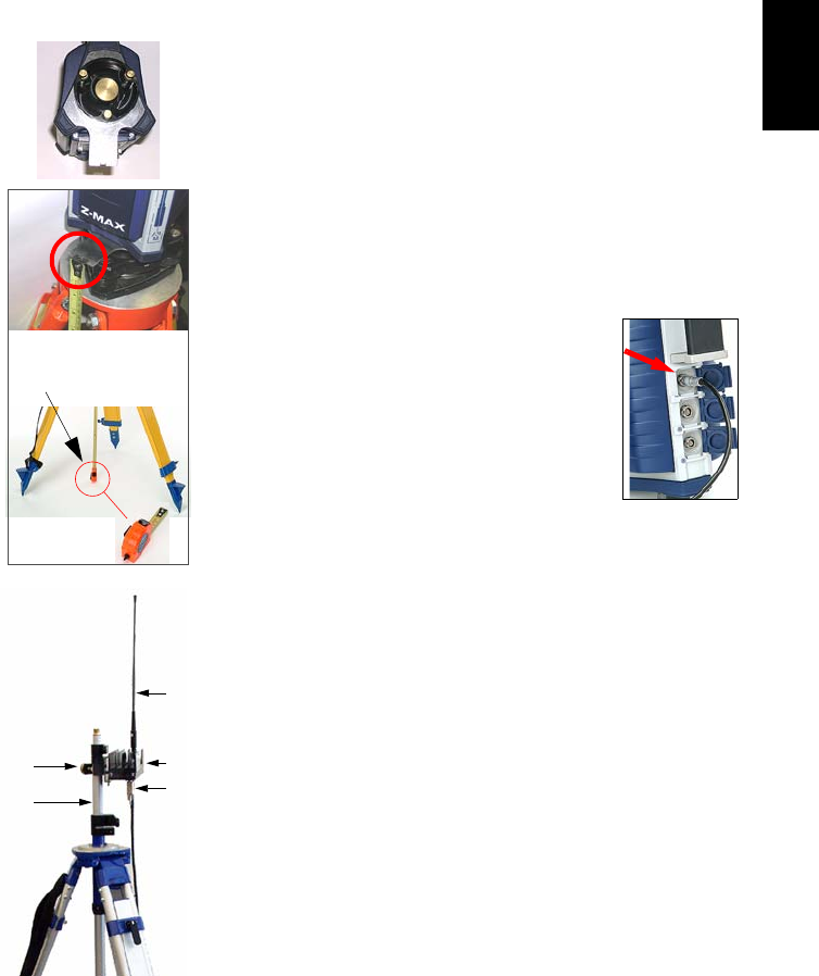
7. Install the tripod for the UHF radio
transmitter a few meters away from the
Z-Max.Net tripod. The distance between
the two tripods is limited by the length (10
meters) of the data/power cable connecting the
Z-Max.Net receiver to the radio (see point 10 below).
8. Screw the radio antenna (A) to the antenna connector on
the U-Link radio (B).
9. Hook the flange on the radio into the mounting bracket
(C), and attach the mounting bracket to the telescoping
survey pole (D).
10. Connect the Y-shaped data/power cable (P/N 730476)
between 7-pin connector port B on the Z-Max.Net and
the 15-pin data/power port on the U-Link radio (E).
11. Connect the free end of the data/power cable to the
battery
12. Raise the UHF radio and its antenna together as high as
possible to maximize transmission distance.
“Hb” read
on tape
(A)
(B)
(C)
(D) (E)
16
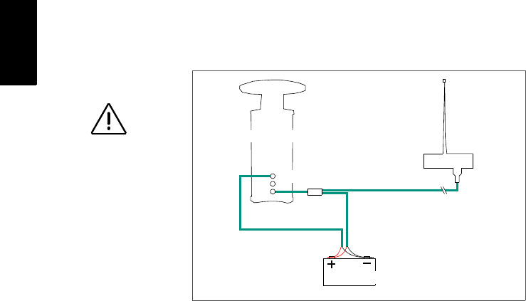
English
The diagram below summarizes the different connections
described previously.
RTK Rover Setup
Two typical RTK rover setups are described:
•Rover Setup #1: RTK rover using a UHF radio data link
to communicate with an RTK base such as the one
described in the previous chapter.
•Rover Setup #2: RTK rover using a GSM/GPRS data
link to acquire corrections data from a provider using the
NTRIP protocol.
Use exclusively a 12-V
DC battery to power
the U-Link transmitter.
Using a 24-V DC bat-
tery is only allowed for
powering the
Z-Max.Net.
A
B
Power
U-Link Transmitter
External 12-V Battery
P/N 730476
P/N 430477
Z-Max.Net
17
English
The rover setup procedure is the following
1. Connect the system components (power module, GNSS
and UHF antenna modules, com module) as explained on
page 9, taking into account the following:
-Rover Setup #1: Because a UHF radio is used as the
data link, a UHF communication module, and not a
V-module, should be attached to the right side of the
receiver module. Connect the UHF antenna module
directly to the top of the receiver module and attach
the GNSS antenna module to the top of the UHF
antenna module.
-Rover Setup #2: Because a GSM/GPRS modem is
used as the data link, a GSM communication module,
and not a V-module, should be attached to the right
side of the receiver module. Because a UHF antenna
is not needed, connect a void UHF antenna module
directly to the top of the receiver module and attach
the GNSS antenna module to the top of the void UHF
antenna module.
2. Mount the Z-Max.Net assembly on the survey pole:
- Remove the brass adapter from the top of the pole
and attach it to the base of the Z-Max.Net assembly.
- Seat the Z-Max.Net onto the pole.
If no adapter is available, just thread the pole directly
on to the base of the receiver.
3. Determine the height of the range pole (see Hr opposite).
If you are using a standard pole, this height is given by
the pole manufacturer so you don’t need to measure it.
You will later have to remember this height when setting
the rover (see point 2. on page 28)
4. Mount the field terminal on its field bracket and then
secure the assembly onto the survey pole.
3.
2.
Hr
18
English
Establishing Bluetooth Communication
with Z-Max.Net
Introduction
This section explains how to control the Z-Max.Net system
from a Bluetooth-enabled field terminal (Thales
MobileMapper CE).
Please carefully read these preliminary notes:
• When using Bluetooth communication, you will be
asked repeatedly to enter the Z-Max.Net PIN number
while setting up the base or the rover. By default, the PIN
number for all Z-Max.Net units is “12345”.
To enter the PIN number using MobileMapper CE’s virtual keyboard,
follow the instructions below:
- To display the virtual keyboard, tap in the task bar and then
Keyboard. Don’t forget to tap inside the Enter PIN field before enter-
ing the PIN number.
- To hide the virtual keyboard, tap in the task bar and then Hide
Input Panel. If the task bar is hidden by the virtual keyboard, first tap
and hold the keyboard’s title bar and move it upward until the task
bar becomes visible, then select Hide Input Panel from the task bar.
• The “Tap and hold an item” instruction mentioned
several times in what follows means you have to:
- Tap on the item using the stylus
- And keep the stylus in contact with the screen until
dots and then a pop-up menu appears. Then you will
have to tap one of the functions in the prompted
menu.
Base
Rover
Field
Ter minal
Bluetooth
Manager
COM3
COM4
19
English
Powering up the Whole Equipment
It is assumed that the base and rover you have set up are
next to each other.
1. First of all, turn on each of the Z-Max.Net units you will
be using (a base and a rover, or simply a rover) by
pressing the power button for about two seconds until a
beep is emitted.
2. Press the red Power button on the MobileMapper CE
until the Power LED lights up (green).
Detecting Bluetooth-Enabled Devices
In this step, you will run Bluetooth Manager to find the
Bluetooth-enabled devices within range of the field
terminal.
1. On the MobileMapper CE, tap in the task bar, then
Settings and then Control Panel.
2. Double-tap the Bluetooth Manager icon.
3. In the Bluetooth Manager window, tap on the ON button.
Wait until Bluetooth Manager has detected the
Z-Max.Net unit(s) you have just turned on. Bluetooth
Manager will also detect any Bluetooth-enabled devices
present in the vicinity such as cell phones, computers,
etc. (The larger the number of Bluetooth-enabled
devices, the longer the time to detect all of them.)
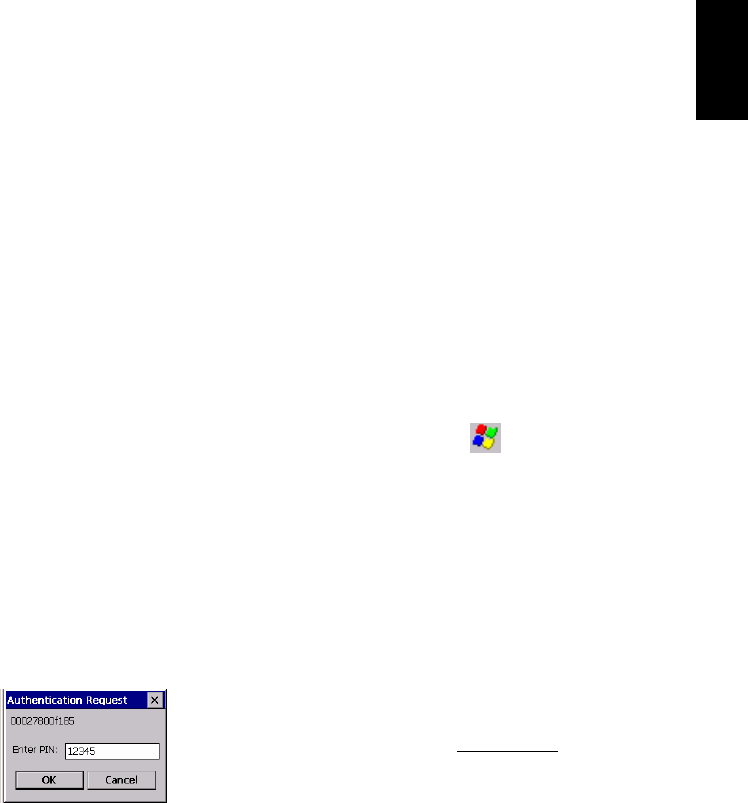
4. In the Authentication Request window that appears
following the detection of the Z-Max.Net units, tap
successively the PIN number for each unit (“12345” by
default, yours may be different) (see Introduction on
page 18 to do this).
5. Tap OK. Bluetooth Manager then updates the list of
Bluetooth-enabled devices to show the serial number of
the Z-Max.Net units (rather than obscure Bluetooth ID
numbers).
20
English
Finding Bluetooth Services
In this step, you will list the services available from the
detected Bluetooth-enabled devices.
For each detected Z-Max.Net unit, do the following:
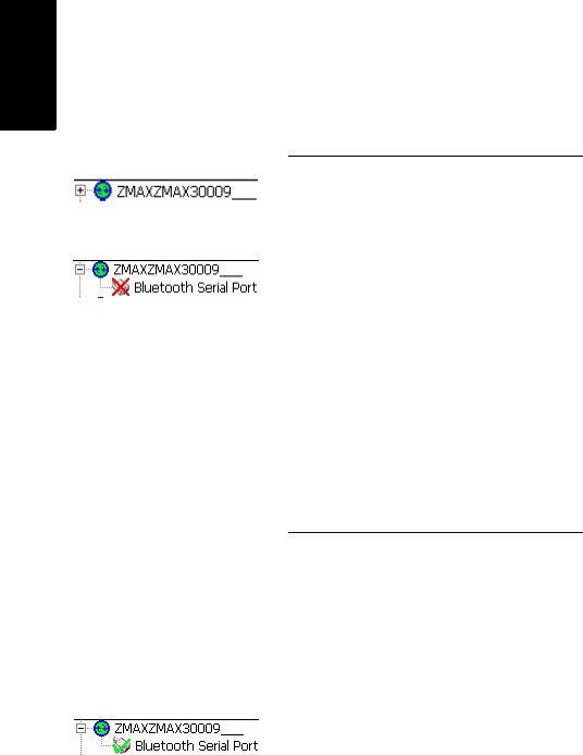
1. Tap and hold the now green Z-Max.Net icon in the list
and then tap Find Services from the pop-up menu. Wait
until a “+” sign appears before the icon.
2. Expand the Z-Max.Net icon by tapping on the “+” sign.
This unveils Bluetooth Serial Port that is currently red
crossed. (“Bluetooth Serial Port” is the only Bluetooth
service available from the Z-Max.Net units.)
Assigning Virtual Ports to Bluetooth
In this step, you will ask Bluetooth Manager to assign a vir-
tual port in the field terminal for each Bluetooth connection
you need.
For each detected Z-Max.Net unit, do the following:
1. Tap and hold Bluetooth Serial Port and then tap Configure.
This opens the Configure Serial Port window.
2. Select a free virtual port (COM3: for the base, COM4: for
the rover) and then tap OK to close the window.
3. Tap and hold Bluetooth Serial Port and then tap Connect.
Re-enter the PIN number if requested. Wait until the
Bluetooth Serial Port line appears with a green mark
meaning that the Bluetooth connection with the Z-
Max.Net is now established.
21
English
Saving Bluetooth Serial Port Settings
You will save much time when next starting your system if
you follow the procedure below the first time you set up the
required Bluetooth connections.
For each detected Z-Max.Net unit, do the following:
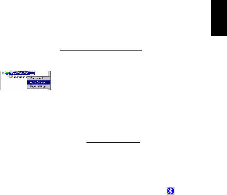
1. Tap and hold Bluetooth Serial Port and then tap
successively Auto Connect and then Save Settings.
With these options activated, and provided you do not
turn off Bluetooth Manager before shutting down the
field terminal, Bluetooth Manager will automatically
restore the Bluetooth connections when you next turn on
your field terminal.
Obviously, Bluetooth Manager will only be able to
restore connections with the Z-Max units that are present
in the vicinity and powered up at that time.
You will then simply be asked to re-enter the PIN
number for each of these units.
Before moving on to FAST Survey, do the following:.
2. Tap OK in the upper-right corner to close the Bluetooth
Manager window. This does not turn off Bluetooth
Manager but simply frees the screen for other tasks.
3. For the same reason, close the Control Panel window.
Note the presence of the Bluetooth icon ( ) in the task
bar meaning that Bluetooth continues to be active.
22
English
Defining/Saving Bluetooth Settings for FAST Survey
FAST Survey can communicate with only one Z-Max.Net
unit at a time. This step provides the procedure to let FAST
Survey communicate with the desired Z-Max.Net unit via
Bluetooth and save these settings in a configuration file so
these settings can quickly be restored whenever necessary.
1. Run FAST Survey on the field terminal
2. In FAST Survey, tap on the Equip tab and then on the
Comm Setup function.
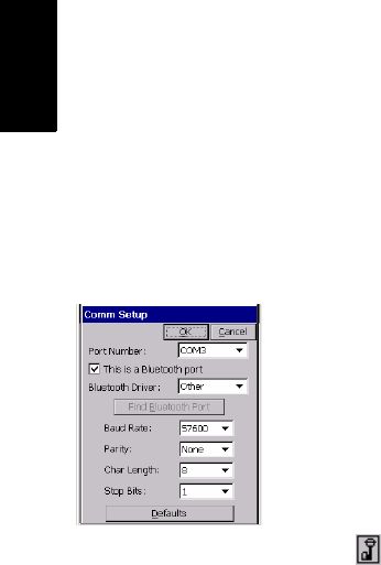
3. In the Port Number field, select “COM3” (for
communicating with the base)
4. Check the This is a Bluetooth port option and then select
“Other” as the Bluetooth Driver
5. Tap OK to close the window. FAST Survey is now
communicating with the base through COM3. At this
stage, you can communicate with the base for
configuration or monitoring purposes.
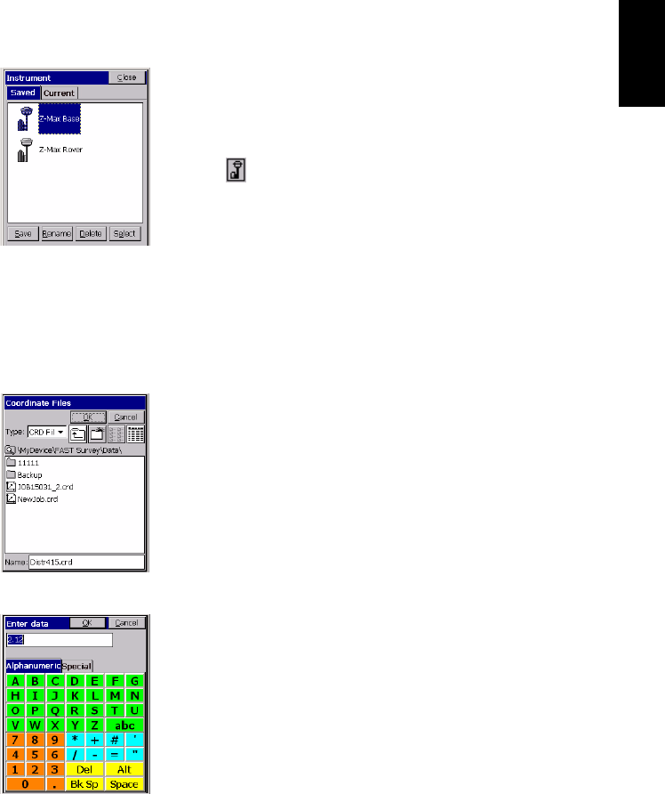
6. Tap on top of the screen
7. Tap the Save button
8. Name the configuration file (for example “Z-Max Base”)
9. Tap OK and then Close
10.Repeat the above steps 2 to 9 for the Z-Max.Net rover
you are using. This time you will select “COM4” and not
“COM3” in the Comm Set up window (point 3.) and you
will enter “Z-Max Rover” as the name for the
configuration file (point 8.).
23
English
Toggling Bluetooth Between Base and Rover
Now that you have saved the two ways FAST Survey can
communicate with your Z-Max.Net system, it’s easy to tog-
gle Bluetooth communication from the base to the rover or
the other way around:
1. Tap on top of the screen
2. Tap on the name of the configuration corresponding to
the unit you wish to communicate with and then tap
Select. As a result, FAST Survey automatically updates
the settings in the Comm Setup function to let you
communicate with the chosen unit.
Configuring the RTK Base
Launching FAST Survey
1. On the field terminal, launch the FAST Survey software
by double-tapping on the FAST Survey icon.
2. Choose Select New/Existing Job. A new screen is now
displayed.
3. In the Name field, type in the name of the job you wish to
create. For example, type in “Job1.crd”.
Note that FAST Survey has its own, large, virtual
keyboard (see opposite). If you tap inside the Name field,
FAST Survey will automatically display its virtual
keyboard. You just have to type in a name using this
keyboard and then tap OK.
4. Tap OK to create the job. The screen then displays the
Units tab.
5. On the Units tab, set the desired units and parameters for
the job.
New Job screen
FAST Survey virtual
keyboard
24
English
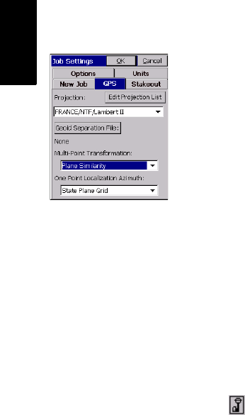
6. Tap on the GPS tab.
7. On the GPS tab, choose the coordinate system to be used
in the job as well as the geoid model. Note that the
coordinate system and the geoid model may have been
uploaded earlier to the field terminal using one of the
GNSS Solutions tools (see GNSS Solutions Reference
Manual for more information). A large number of
coordinate systems are stored in FAST Survey. To select
one of them, tap on the Edit Projection List button and then
Add Predefined.
8. After selecting all the desired parameters, tap OK (located
on top of the screen).
Configuring the Base and the Data Link
Reminder: In this example, you will be configuring a UHF
data link to provide the rover with RTK corrections data in
CPD (DBEN) format.
1. Tap on the Equip tab, then the Instrument function, select
“Thales/Ashtech” from the scroll-down menu and finally
tap OK.
2. Tap on top of the screen
3. Tap on the name of the configuration corresponding to
the base (e.g. “Z-Max Base”) and then tap Select. As a
result, FAST Survey automatically updates the settings in
the Comm Setup function to let you communicate with the
base.
Alternately, you can tap on the Comm Setup button on the
Equip tab and then, in the Port Number field, select the port
you assigned to communicate with the base (see point 2.
in Assigning Virtual Ports to Bluetooth on page 20).
Also, enable “This is a Bluetooth port” and select
“Other” as the Bluetooth Driver. Then tap OK
4. Tap on the Configure Base button and then choose
“Z-Max” from the Receiver Type scroll-down menu.
GPS tab screen
25
English
5. Enter the antenna height you measured previously (see
point 5. page 15) as well as the method you used for this
measurement. If you used the method described on
page 15, check Slant.
6. Select the type of GPS antenna used, i.e. “[Z-Max GPS]
Thales Navigation” as you are using the Z-Max.Net
antenna directly connected to the receiver.
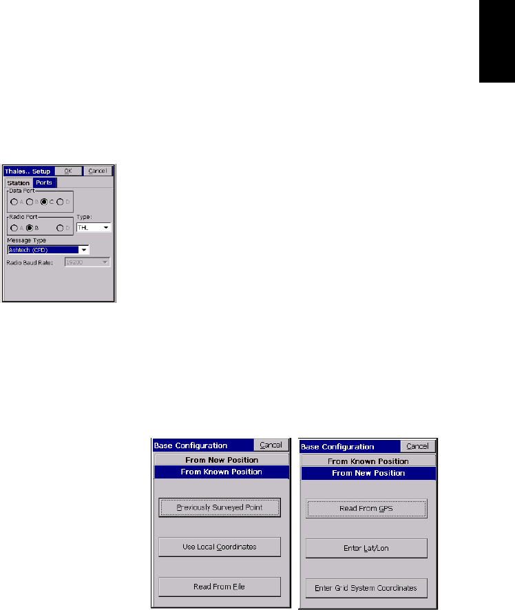
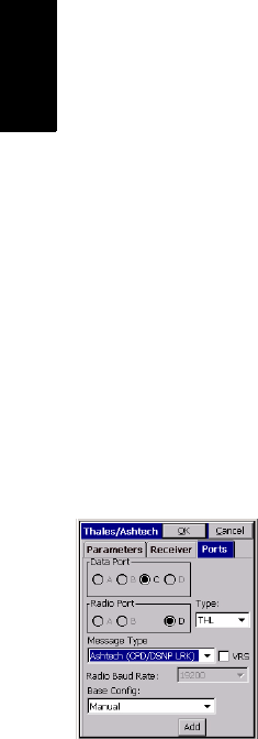
7. Tap on the Ports tab. With Bluetooth and the Thales radio
used, make the following choices:
• Type: “THL” (Thales Radio)
• Data Port: “C” (Bluetooth connection to field
terminal)
• Radio Port: “B”
• Message Type: “Ashtech CPD”.
8. Tap OK to send these parameters to the Z-Max.Net
receiver. Re-enter the PIN number. The Z-Max.Net emits
a beep. A new menu appears asking you to enter the
initialization position for the base.
Entering the Base Position and ID
Up to six different options are possible to enter this
position:
26
English
9. Choose the option that suits you best. For example, to
enter the coordinates of the base:
- Tap successively on From New Position, then Enter Lat/
Lon
- Type in the latitude, longitude and altitude and then
tap OK. FAST Survey then displays the WGS84 coor-
dinates of this position after making the transforma-
tion to WGS84 if necessary.
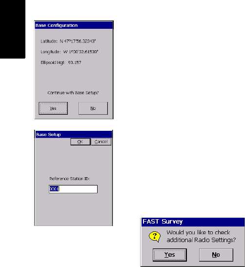
-Tap
Yes.
10.FAST Survey then asks you to enter the Reference Station
ID (4 characters max.).
11. Enter the ID you would like to assign to the base and
then tap OK. The message “Connecting to Receiver” is
displayed and a beep is emitted meaning that the
Z-Max.Net is being configured. After a few seconds,
FAST Survey prompts you to check the radio settings:
Setting the Radio
12.Tap Yes. In the US, a channel/frequency table will be
shown. In Europe, a single channel will be displayed
along with the corresponding frequency.
13.For example, if the frequency must be set to
444.125 MHz (it’s always a multiple of 12.5 kHz), type
in “444.125” in the Frequency to Set field and then tap Set
Radio.
14.Wait until FAST Survey displays the “Base Configuration
Successful” message and the Z-Max.Net emits a beep.
Base coordinates screen
Base Station ID screen
27
English
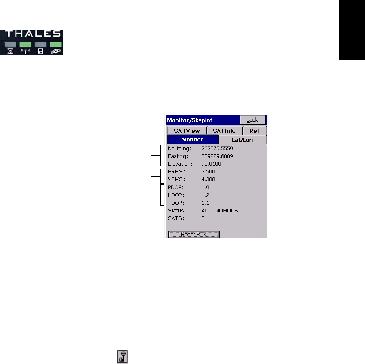
15. Check the LEDs on the Z-Max.Net front panel to make
sure the system is functioning correctly (refer to page 4
to read the meaning of each LED). Typically, two LEDS
should blink green as shown opposite.
You can also monitor the Z-Max.Net rover from the
MobileMapper CE screen using FAST Survey’s Equip
tab>Monitor Skyplot function (see figure below).
Tap Back to return to the menu.
16. You can now let the base operate on its own and move on
to the rover configuration. Keep the field terminal on.
Also, keep FAST Survey running and leave the job open
as this is needed to configure the rover (see hereafter).
Configuring the RTK Rover
1. Tap on top of the screen
2. Tap on the name of the configuration corresponding to
the rover (e.g. “Z-Max Rover”) and then tap Select. As a
result, FAST Survey automatically updates the settings in
the Comm Setup function to let you communicate with
the rover.
Current position
Computation
uncertainties
Number of
received satellites
GPS constellation
geometry
28
English
Alternately, you can tap on the Comm Setup button on the
Equip tab and then, in the Port Number field, select the port
you assigned to communicate with the rover (see point 2.
in Assigning Virtual Ports to Bluetooth on page 20).
Also, enable “This is a Bluetooth port” and select
“Other” as the Bluetooth Driver. Then tap OK.
Case #1: Rover Using a UHF Radio Data Link
1. Tap on Configure Rover
2. In the Rod Hgt field, type in the height mentioned earlier
(Hr; see point 3. on page 17) and then check the Vertical
option.
3. Tap on the Receiver tab and check that the receiver used is
“Z-Max”. Also, as you are using a UHF antenna module
-although a void one- between the GNSS antenna and the
receiver module, select the “[Z-Max GPS UHF] Thales
Navigation” antenna in the Antenna Type field.
4. Tap on the Ports tab and make the following choices:
-Base Config field (at the bottom): “Manual”
- Type: “THL” (Thales radio)
- Data Port: “C” (Bluetooth connection to field
terminal)
- Radio Port: “D”
- Message Type: “Ashtech (CPD/DSNP LRK)”
5. Tap the OK button located on top of the screen. The
message “Connecting to Receiver” is displayed and the
Z-Max.Net emits a beep meaning that it’s being
configured.

29
English
6. After a few seconds, another message is displayed
prompting you to check the radio settings:
7. Tap Yes. In the US, a channel/frequency table will be
shown. In Europe, a single channel will be displayed
along with the corresponding frequency.
8. For example, if the frequency must be set to
444.125 MHz (it’s always a multiple of 12.5 kHz), type
in “444.125” in the Frequency to Set field and then tap Set
Radio.
9. Wait a few seconds. A beep is emitted by the Z-Max.Net
once it has been configured as a rover.
The survey can now begin.
You can first check the LEDs on the Z-Max.Net front
panel to make sure the system is functioning correctly
(refer to page 4 to know the meaning of each LED).
You can also monitor the Z-Max.Net rover from the field
terminal screen using FAST Survey’s Equip tab>Monitor
Skyplot function.
30
English
Case #2: Rover Using a GSM/GPRS Data Link
Reminder: You do not need to install and run your own
base as in this case you will be using RTK corrections data
from a provider using the NTRIP protocol. This means you
just have to set up and use your rover. Below is the key
information you need to know in this case of use:
• A GPRS data link is used to receive RTK corrections
data from an NTRIP caster. The GPRS provider is
assumed to have delivered the following information so
you can start your modem:
• The NTRIP service provider is assumed to have
delivered the following information so you can access
the NTRIP service:
Follow the instructions below to set up the rover:
1. Tap on Configure Rover
2. In the Rod Hgt field, type in the height mentioned earlier
(Hr; see point 3. on page 17) and then check the Vertical
option.
3. Tap on the Receiver tab and check that the receiver used is
the Z-Max.Net. Also, select the “[Z-Max GPS UHF]
Thales Navigation” antenna in the Antenna Type field.
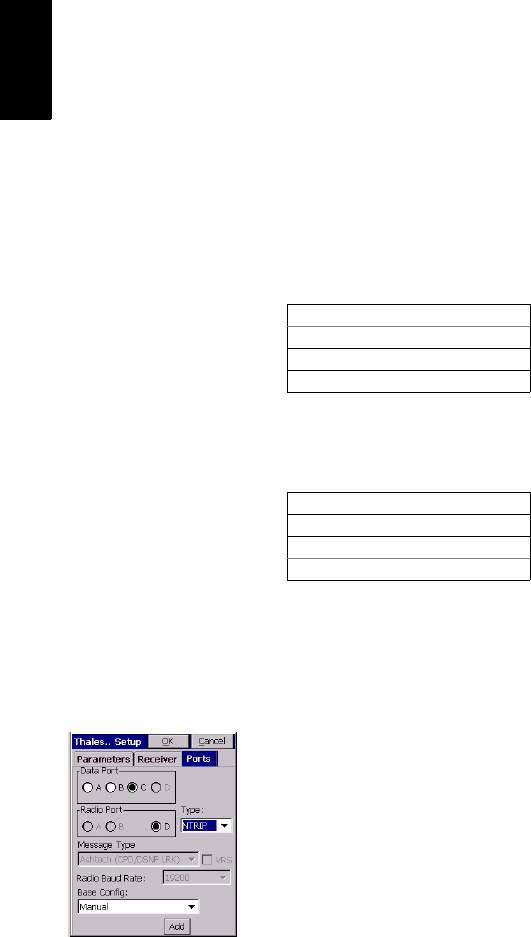
4. Tap on the Ports tab and make the following choices:
-Base Config field (at the bottom): “Manual”
Modem SIM PIN number (if any)
Access Point Name
Log in for GPRS connection
Password for GPRS connection
Caster IP address (xxx.xxx.xxx.xxx)
IP port number
Log in for access to NTRIP caster
Password for access to NTRIP caster
31
English
- Type: “NTRIP”
- Data Port: “C”
5. Tap the Add button located at the bottom of the screen.
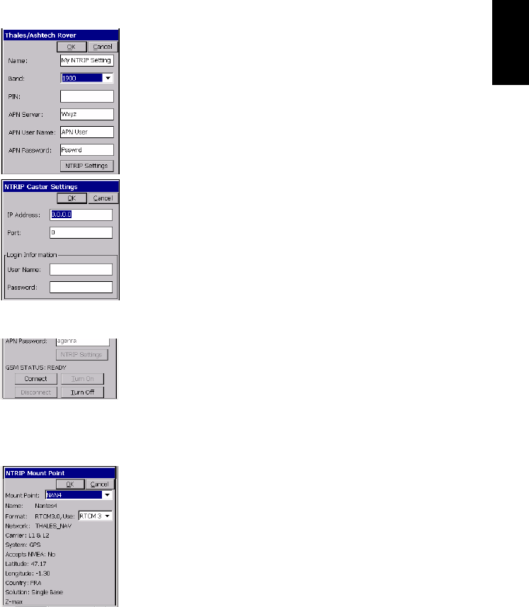
6. Enter the properties of the GPRS provider. The screen
opposite only gives examples of what these properties
might be.
By appropriately naming this set of information (Name
field on top), you will be able to directly select this
configuration from the Base Config field on the previous
screen.
7. Tap the NTRIP Settings button and enter the properties of
the NTRIP service you want to use. The screen opposite
only gives examples of what these properties might be.
8. Tap OK three times.
9. The message “Connecting to Receiver” is displayed and a
beep is then emitted indicating that the Z-Max.Net is
being configured.
A new screen appears on which you can see the current
status of the com module’s modem (READY; see screen
opposite).
10. Tap Connect. The Connecting to Caster message is
displayed. Then a new screen appears from which you
can see all the stations available from your NTRIP
provider
11. From the drop-down list associated with the Mount Point
field, select the base station you would like to work with.
The rest of the screen provides information on the
selected station. The Format field is automatically preset
following the selection of a station but you can still
change it if the pre-setting is incorrect (see screen
opposite).
32
English
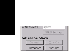
12.Tap OK. After a while, The GSM STATUS switches to
ONLINE (see screen opposite) and the Z-Max.Net
should start receiving corrections data. After a few
seconds the RTK Solution LED (far left) should blink
green meaning that the RTK position solution is fixed
and so you can start surveying.
13.Tap Close and proceed with the survey as such (see next
chapters).
You can monitor the Z-Max.Net rover from the field
terminal screen using FAST Survey’s Equip tab>Monitor
Skyplot function.
Saving Base and Rover Settings
When you configure your base or rover from FAST Survey,
a Save operation is automatically performed at the end of
the procedure and so you don’t need to save anything manu-
ally.
After a power cycle, your base or rover will therefore con-
tinue to operate according to the last loaded configuration.
Running an RTK Survey
If you have followed all the instructions provided in this
RTK Surveying chapter, your rover is now fully configured
and so you can start your survey using your field-terminal-
controlled rover.
NOTE: To start the survey with the correct antenna height
when using FAST Survey, the rover should always have
been set up last.
The present section describes the main types of surveys you
can perform with FAST Survey and your Z-Max.Net,
namely:
- RTK point logging (Stop & Go survey)
- RTK point logging in continuous mode (trajectory sur-
vey)
- RTK staking out.
33
English
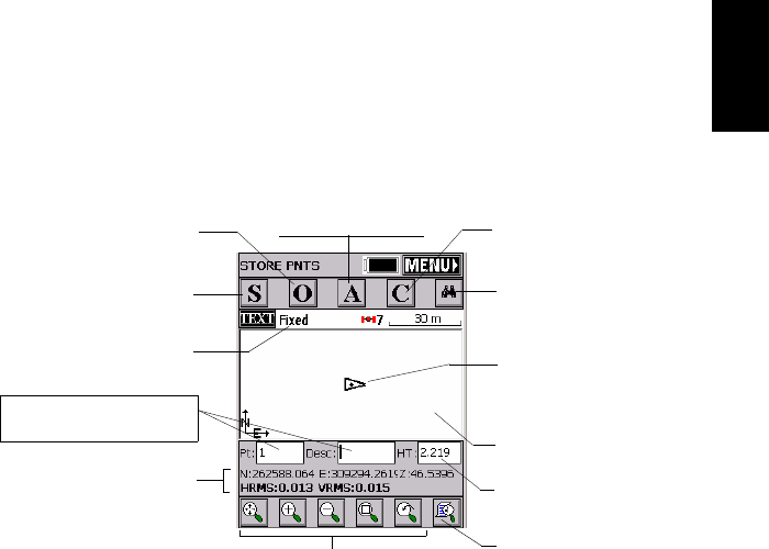
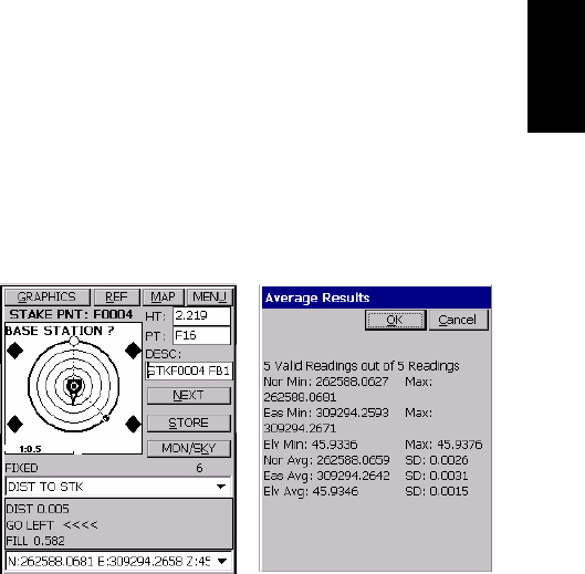
Logging RTK Points
1. Tap on the Surv tab and then on Store Points. The screen
now displayed allows you to log all your points.
The figure below summarizes all the functions available
from that screen.
For example, you are on a point that you want to log. Do
the following:
2. Type in the point name and description in the
corresponding two fields (see above)
3. Tap on the “A” button
4. Enter the number of readings you want before FAST
Survey is allowed to compute an average position for this
point. For example, type in “5” and tap OK.
Messages follow successively indicating that the system
is taking the 5 requested readings. Then FAST Survey
displays the average coordinates it has determined.
5. Tap OK if you agree. The “Point Stored” message appears
briefly. The screen then shows the location of the point
together with its name and description.
Logging point
with offset
GPS antenna height
Current position and related
quality figures
Enter the point name and
description in these two fields Graphic Display area
Your current position
and heading
Logging point
(general case)
Provides access to
monitor screen
Viewing parameters
Zoom settings
Logging point with
position averaging Configures general
case of point logging
Current status of
position solution
34
English
6. After logging all your points, tap MENU in the upper-
right corner of the screen to return to the menu.
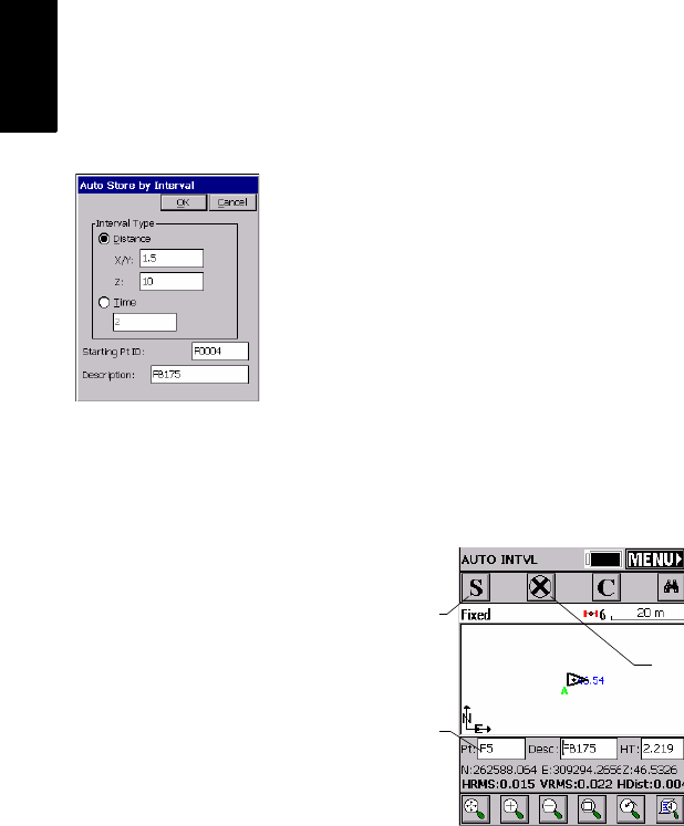
Logging RTK Points in Continuous Mode
1. On the Surv tab, select the Auto by Interval function. Two
different modes are possible: Time or Distance.
2. If you choose Distance, enter the horizontal and vertical
increment value respectively in the X/Y and Z fields,
according to the chosen unit. If you choose Time, enter
the increment value, in seconds.
3. Enter a point Id. for the start point in the Starting Pt ID
field. This field will be incremented by one after each
point logging. You do not need to define a name
finishing with a figure. FAST Survey will place one
anyway when incrementing this field.
4. Press OK to switch to the graphic screen (see figure
below) and start logging the first point.
The S button lets you instantly log the position of a point.
The X button allows you to pause data logging in
continuous mode.
If data logging in continuous mode is paused, you can
still continue to log points in manual mode using the S
button.
Used to pause/resume
data logging
Point Id.
incremented
automatically
Used to log a point’s
position manually
35
English
Tap the X button again (changed into a right arrow during
pause) to resume data logging in continuous mode.
If you come back to the main menu by tapping on
MENU, then data logging in continuous mode is
automatically stopped.
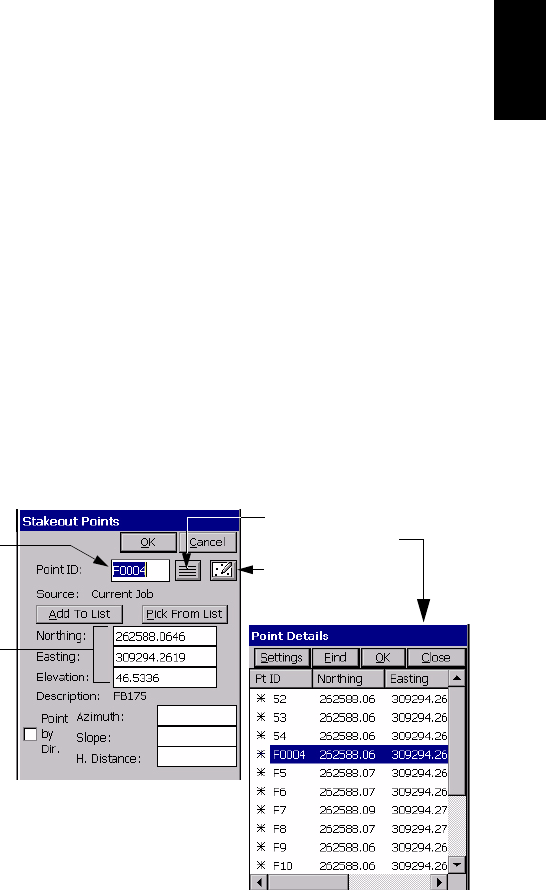
Staking out RTK Points
1. Tap on the Surv tab and then select Stakeout Points. The
screen now displayed allows you to stake out your
points.
2. On this screen, FAST Survey asks you to choose the
point you want to stake out. You can either type in its
coordinates in the Northing, Easting and Elevation fields, or
select a pre-defined point from the points list (see
File>List Points). You can also, define graphically this
point by tapping on the point on the graphic screen, or
define that point according to azimuth, slope and
horizontal distance.
Coordinates of point
to be staked out
Name of point to
be staked out Provides access to
graphic screen
Provides access to points list.
Example of points list:
36
English
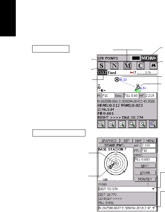
3. Once you have chosen a point, tapping on the OK button
will display a graphic screen from which you can easily
stake out your point:
The target radius is automatically changed as the
distance from you to the point changes.
When getting closer to the point, markers appear at the
four corners of the target (see below left) informing you
that you have arrived at the target. You can now
materialize and log the position of this point.
4. Tapping on the STORE button allows you to start
performing measurements to determine the target
position.
Your current position and
heading
Provides access to
monitor screen
Takes you back to the point
selection screen
Point to be staked out (target)
Provides access to the detailed
stakeout screen below
Stakeout screen
Detailed stakeout screen
Next point
Logs the point
Your current position
and heading
Point to be staked out
Used to select which guidance
data to display
Used to select which data to
display for the point:
coordinates or quality data
Configures general
case of point logging
37
English
The number of measurements will depend on the value
entered earlier through the File tab>Configure Readings
function. Once the position has been determined, FAST
Survey displays the results of the computation so that
you can check them (see below right).
5. Tap OK if you are satisfied with the results. FAST Survey
will then save these results and will take you back to the
stakeout screen for the next point.
Downloading RTK Results to GNSS Solu-
tions
Back at the office, do the following to download and view
the RTK results stored in the job you have just finished.
1. Prepare your field terminal for data downloading. With
MobileMapper CE, do the following:
- Clip the I/O module at the back of the unit.
- Connect the MobileMapper CE’s I/O module to the
PC using the USB cable provided.
2. Switch on the field terminal and then launch FAST
Survey
3. Select File>6. Data Transfer>Carlson SurvCadd/Carlson Survey.

38
English
4. On the PC:
- Launch GNSS Solutions and then click Create a new
Project
- Name the project and click OK
- Select the spatial reference system that was used
during your RTK survey, select the appropriate time
zone and then click OK
- Click Do Not Import Anything Now. A new empty project
opens in GNSS Solutions.
- Select Tools>Preferences and make sure Show RTK
functions is enabled otherwise check it and then click
OK
- From the menu bar, select Project>Download Positions
from External Device
- In the dialog that opens, select RTK Results in the left
pane and then FAST Survey data collector in the right
pane
- Click OK. This opens the Data Transfer dialog box.
- To be able to configure the connection to the
MobileMapper CE the first time you download RTK
results, clear the Automatic transfer option and then
click OK. Two error messages may appear in the next
step. Just click OK when this happens. The SurvCom
window then appears on the screen.
- In the SurvCom window, click on the Options button
and then select the ActiveSync option in the upper-
right combo box (this option is last in the list)
- Click OK
- Select the “Data” folder on the MobileMapper CE
and click Exit
- In the new dialog that appears, you can now see the
list of jobs stored in the MobileMapper CE
- Click on the job you want to download. The name of
the selected job appears in the upper field.
-In the Directory field, choose the folder on your PC
where you would like to store this job
- Click OK. RTK results are now downloaded to the
project open in GNSS Solutions. At the end of the
transfer, these results can be seen on the project’s
Survey view.
NOTE: When next
downloading RTK
results, the connection to
the field terminal does
not need to be re-
configured. This means
you can skip this step by
checking the Automatic
Transfer option in the
Data Transfer dialog box.
39
English
4. Post-processing Surveying
This chapter only discusses the static mode of surveying.
For more information on Continuous (Trajectory) or
Stop&Go kinematic methods, please refer to the Z-Max.Net
Reference Manual.
Reminder on the Static Surveying Method
Typical Use: Surveying a New Control Point.
Key Instructions:
1. Two units needed: one (the base) operated on an accurately known
position and the other (the rover) on the point to be surveyed. There
can be several rovers logging data at the same time.
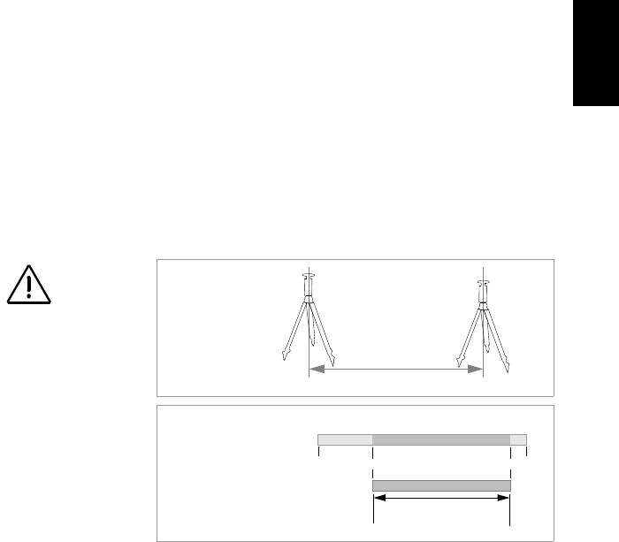
2. Approximate distance between the two units (baseline) must be
known.
3. Data must be collected simultaneously by the two units. Use the
same logging interval on both units.
4. Observation time is determined by last unit set up (start) and first unit
turned off (end). We recommend that you start the base first and you
turn it off last.
5. Required observation time mainly depends on distance between the
two units (+ reception conditions). Rover unit estimates observation
time needed.
When Estimated Base Line Len on the Z-Max.Net front panel
decreases down to “000km”, you can stop collecting data.
Make sure the base is
sited in a clear area giv-
ing the best possible
view of the sky!
When this is possible,
avoid trees, buildings or
any high obstacles in the
vicinity of the base.
Having a clear view of
the sky will allow the
base to collect data from
a maximum of visible
satellites, which is highly
recommended to perform
a successful, accurate
and fast survey.
Data collected on surveyed point:
Base
Baseline
(Range)
Observation time
Data collected at base:
Time Organization
Equipment Involved -
Field Organization
Known Point Survey Point
Rover

40
English
Running a Static Survey
A typical survey is described in this chapter using a conven-
tional tripod. No field terminal is used as controlling system
operation from the Z-Max.Net front panel is quite easy in
this case.
Equipment Setup
The equipment setup instructions are the same for both the
base and the rover. Install and run the base first.
In both cases, the installation site should offer the best pos-
sible GPS reception conditions. The antenna should have a
clear view of the sky in all directions. There should be no,
or a minimum of satellite obstructions in the vicinity.
1. Make sure the chosen point is suitable for GNSS obser-
vations.
2. Connect the system components as explained on page 9.
For postprocessing surveys, a V-module, and not a com-
munication module, should be attached to the right side
of the receiver module.
3. A memory card is required to log raw data. Insert this
card as explained on page 10. Formatting a memory card
for the Z-Max.Net requires that you re-initialize the
Z-Max.Net with the SD card inserted (see page 11).
4. Position the tripod over the chosen point
5. Insert the brass tribrach adapter through the hole in the
HI measurement plate and screw the adapter/plate into
the 5/8” threaded receptacle in the bottom of the
Z-Max.Net receiver module.
41
English
6. Once the tripod is accurately centered and leveled over
the point, and the tribrach adapter and HI measurement
plate are attached to the receiver module, carefully place
the assembly into the tribrach mounted on the tripod over
the point.
7. Use the tape measure to measure from the center of the
point to the measurement point of the Z-Max.Net (see
Hb opposite). Later on, you will have to enter the value
read on the tape (see point 4. on page 42).
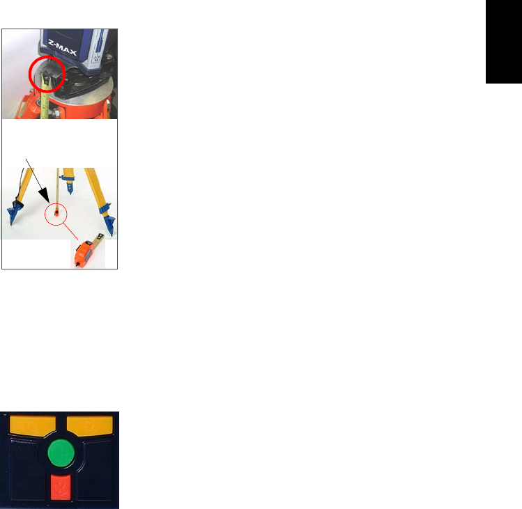
Getting the Z-Max.Net Unit Started in Static
1. Press the Power button on the receiver module front
panel for 2 seconds until a beep is emitted.
2. Configure the system to perform a static survey: By
default, the Z-Max.Net system is configured to perform a
static survey. When turned on and once enough satellites
are received above 10 degrees of elevation, the receiver
automatically begins to collect and store data in a new
data file with a data recording interval of 10 seconds.
In the event the Z-Max.Net would not be configured to
run in static, do the following to re-configure the
Z-Max.Net:
• Press the Down key until SURVCONF is displayed
• Press the Enter key
• Press the Down key and then the Enter key again
• Press the Down key until STATIC is displayed
• Press ENTER The screen now displays MODE:STATIC.
(The front panel interface is thoroughly described in the
Z-Max.Net Reference Manual. See also page 48 in this
guide.)
“Hb” read
on tape
Down key
Enter key
Cancel key
Up key

42
English
3. Enter the Site ID:
• Press the Cancel key to return to SURVCONF
• Press the Down key until the screen displays
SURVEY:STATIC
• Press the Enter key. SITE ID:??? is displayed. You can
now enter the site ID:
• Press the Enter key again
• Enter the first of the four characters making up the
Site ID pressing the Up or Down arrow until the
desired character is displayed, then press Enter. Set
the second character using the same Up or Down key,
etc.
• After defining the last character, press the Enter key
to validate the site ID. The screen displays the
entered site ID (e.g. “SITE ID:0005”)
4. Enter the Hb height measured earlier with the tape (see
point 7. on page 41):
• Press the Up key. The screen displays ANT HT:..
• Press the Enter key
• Enter the first character of the antenna height meas-
ured previously using the Up or Down key, then press
Enter. Set the second character using the same Up or
Down key, etc.
• After defining the last character, press the Enter key
to validate the HI. The screen displays the entered HI
(e.g. “ANT HT:01.5703m”)
5. Set the recording interval:
• Press the Cancel key to return to SURVEY:STATIC
• Press the Up key until SURVCONF is displayed
• Press the Enter key. You can now enter the recording
interval:
Down key
Enter key
Cancel key
Up key

43
English
• Press the Enter key
• Enter the first character of the recording interval
using the Up or Down key, then press Enter. Set the
second character using the same Up or Down key,
etc.
• After defining the last character, press the Enter key
to validate the recording interval. The screen displays
the entered interval (e.g. “REC INT:20.0s”)
6. For the static “rover” only, enter the approximate length
of the baseline:
• Return to the SURVEY:STATIC root menu, press Enter,
press the Up key twice and then enter this length
(ESTIMATED BASELINE LEN:xxxkm). This parameter is
very important as it will be used by the Z-Max.Net to
help you determine the end of data collection.
Starting Data Collection
1. Start raw data logging as follows:
• Return to the root menu and then press the Down key
until SESSIONS is displayed
•Press Enter. START SESSION is now displayed.
• Press Enter again. Start Session? is now displayed.
• Press Enter again. DONE is displayed for a few sec-
onds. Data logging is now in progress as indicated on
the Data Log LED which should blink green once at
the frequency of the data recording interval.
End of Data Collection
1. Return to the SURVEY:STATIC root menu, press Enter,
press the Up key twice. The screen should now display
the ESTIMATED BASE LINE LEN parameter.

44
English
2. Let the Z-Max.Net rover collect data until this parameter
goes down to “000 km”. A message is then displayed
informing you that you can stop data collection. But
always use your own judgement to decide the moment
when to stop data collection.
Remember the amount of data required is dependent on a
number of factors including:
- The quality of the satellite geometry (PDOP),
- The number of satellites above the elevation mask,
- Any obstructions between the satellites and the GPS
antenna
- The distance (or vector length) between the receivers
collecting data simultaneously.
3. To end data collection, just turn off the Z-Max.Net sys-
tem by pressing the Power button for 2 seconds. When
the receiver is powered down the active measurement
file is automatically closed.
When the receiver is powered back up a new measure-
ment file will be automatically created.
After data collection is complete, take all Z-Max.Net
systems used in the survey to the office and download
the data to an office computer as described in Download-
ing Field Data to your PC on page 45. The data is now
ready for post-processing using GNSS Solutions.
45
English
Downloading Field Data to your PC
The easiest and fastest way to download your field data is to
use the card reader attached to the office PC. This procedure
is described in the present section. It is assumed that GNSS
Solutions has already been installed on your PC.
If you don’t have a card reader, you can download your
field data directly from the Z-Max.Net via a USB or RS 232
link. This procedure is described in the Z-Max.Net Refer-
ence manual. Please refer to this manual for more informa-
tion.
Back in your office, do the following to download your
field data.
1. On the Z-Max.Net:
- Remove the SD card from the Z-Max.Net
- Insert the SD Card in your local SD card reader.
2. On the PC:
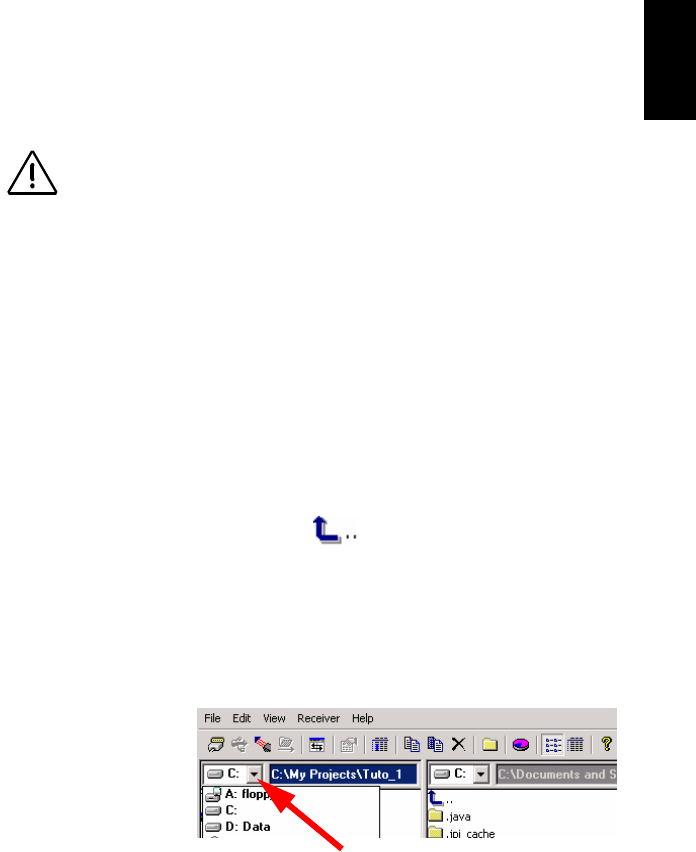
- From the Windows task bar, select Start>Pro-
grams>GNSS Solutions>Tools>Download.
(Double-click in the right side of the window if
you want to change to the parent directory and open
another folder on your PC.)
- In the Download window, click on the drive combo
box (see below) in the left-hand pane and select the
letter corresponding to the local SD card reader
(example: SD card reader is “F:”).
After downloading your
field data, do not forget to
re-insert the SD card into
the Z-Max.Net before tak-
ing it back to the field!

46
English
The left side of the Download window then lists the
files present on the SD card.
- Select the files you want to download. If necessary,
hold down the Ctrl key to make a multiple selection.
-Press the F5 key. A Copying file dialog appears during
data transfer.
After the transfer is complete, notice in the right side
of the Download window that each downloaded file
has been split into different files named with a prefix
as explained opposite.
- Close the Download window.
3. Repeat the previous two steps for each of the Z-Max.Net
units involved in the project to download their respective
files to the same project folder on your office computer.
Post-Processing Field Data
1. On your office computer, launch GNSS Solutions
2. Click Create a New Project, enter a project name and then
click OK.
3. Click Import Raw Data from Files.
4. Browse your computer to change to the folder containing
the data files you have just downloaded.
5. Select the files you want to import and click Open.
Files resulting from the
downloading of an
observation file are
named as follows:
X<Downloadedfilename>
where prefix X = “E” for
Ephemeris Data, “B” for
Position Data, “D” for
GPS Raw Data and “W”
for SBAS Data.
47
English
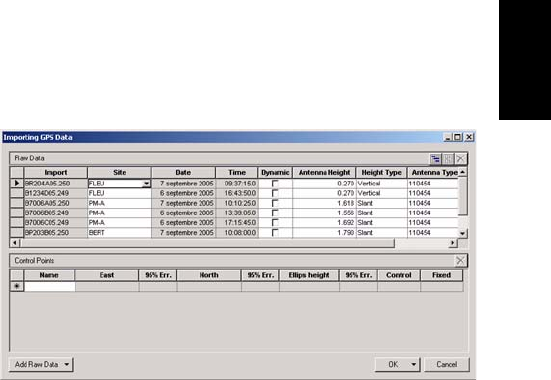
The Importing GPS Data dialog lists the files you want to
import (top). Each row describes one of these files (file-
name, associated Site ID, etc.)
6. At the bottom of the window, define which of the sites is
the control point (base) and enter or check its known
coordinates. You can also fix the control point if neces-
sary by selecting one of the options available in the Fixed
column. If you select <Blank>, the point won’t be fixed.
7. Click OK>To Import to import the data into the project.
Depending on the type of survey, you can go even faster
by running, in one operation, the Import, Process and
Adjust functions.
For more information on GNSS Solutions, please refer to
the GNSS Solutions Reference Manual.
48
English
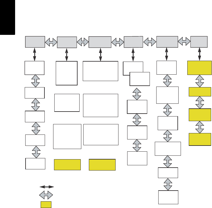
5. Front Panel Interface Function
Diagram
SYSINFO SURVEY:
Current Mode SURVCONF SESSIONS SETTINGS COM
OPTN
RCVR
VERSION
RCVR
S/N
OPTIONS
BAT
MEM RTK ROVER
STATIC
SITE
ANT HT
BASELINE
STATUS
OR
RTK BASE
SITE
ANT HT
ANT RAD
BASE POS
STATUS
OR
OR
KINEMATIC
SITE
ANT HT
STATUS
RTK ROVER
STATIC
OR
RTK BASE
PORT/TYPE
REC INT
ELEV MASK
Select SURVEY MODE
OR
OR
REC INT
ELEV MASK
SBAS
Select SURVEY MODE
KINEMATIC
EPOCH CNTR
MIN SV
REC INT
ELEV MASK
Select SURVEY MODE
STOP
SESSION
START
SESSION
LIST
SESSION
NEW
SESSION
DELETE
ALL
MEMORY
RESET
RESET TO
FACTORY
DEFAULTS
BAUD
RATE
LANGUAGE
BEEP
SAVE
THALES
RADIO
PDL
GSM
ROVER
GSM
BASE
Symbology:
Thin arrow - Enter or Cancel Key
Thick Arrow - Up or Down Key
See Reference Manual

English
Index
A
Access Point Name 30
Auto connect (Bluetooth) 21
B
Backpack 2, 13
Baseline 13, 39
Baseline length 43
Bluetooth 18
Bluetooth icon 21
Bluetooth port 4
C
Caster IP address 30
Cellular modem 13
Charger 2, 8
Charging the power module 8
Collar (threaded) 10
Communication LED 4
Communication module 2
Control keys 5
Coordinate system 24
D
Data collection 43
Data link 13, 24
Data Log LED 4
DBEN 14, 24
Detecting Bluetooth devices 19
Display mode 5
Downloading field data 45
E
Edit mode 5
Entering base position 25
Entering height 15, 17, 25, 28, 42
Estimated baseline length 43
External power 15
External Power In 6
F
FAST Survey 13
FAST Survey CD 2
Field bracket 1
Finding Bluetooth services 20
Flattened area 9
Formatting, re-formatting SD card 11
Front panel display 5
Front panel interface 41
G
Geoid model 24
GNSS antenna module 2, 7
GNSS Solutions CD 2
GNSS Solutions software 45
GPRS 13, 30
GPS receiver module 2, 3
GPS-RF cable 2
H
Handle 6
HI measurement plate 2, 15, 40
HI measurement tool 2
I
Initializing 11
Inserting modules 9
IP port number 30
J
Job 23
Juniper Allegro CX 2
L
Latch 9
Log in for access to NTRIP caster 30
Log in for GPRS connection 30
Logging interval 39
M
Max RF adapter 2
Modem SIM PIN number 30
Monitor skyplot 27, 29
Mounting bracket 2
N
NTRIP 30
O
Observation time 39
Ordering information 1
Other external device 13
P
Pacific-Crest UHF Transmitter 2
Password for access to NTRIP caster 30
Password for GPRS connection 30
PIN number 18, 19
Port A 6
Port B 6
Post-processing field data 46
Power key 6
Power Module 2

English
R
Range pole 2
Range pole RF adapter 2
Range-Pole 13
RTCM 3.0 31
RTK Solution LED 4
S
Satellite/Power LED 4
Saving Bluetooth connections for FAST
Survey 22
Saving Bluetooth settings 21
SD Card 2, 10
SD card reader 6
Serial data cable 2
Site ID 42
Soft case 2
Stake out 35
Static 41
Status LEDs 4
Stop & Go 39
T
Tap and hold 18
Thales MobileMapper CE 2
Thales U-Link transmitter 2
Toggling from base to rover 23
Trajectory 39
Turning On/Off 10
U
UHF antenna module 2
UHF radio 13
UHF-RF cable 2
U-Link 14
Units 23
USB cable 2
USB port 6
V
Virtual (ports) 20
V-module 2, 3

Thales
Survey Solutions Contact Information
In USA +1 408 615 3970 • Fax +1 408 615 5200
Toll Free (Sales in USA/Canada) 1 800 922 2401
In South America +56 2 273 32 14 • Fax +56 2 273 31 87
Email surveysales@thalesnavigation.com
In Singapore +65 6235 3678 • Fax +65 6235 4869
In China +86 10 6566 9866 • Fax +86 10 6566 0246
Email surveysalesapac@thalesnavigation.com
In France +33 2 28 09 38 00 • Fax +33 2 28 09 39 39
In Germany +49 81 6564 7930 • Fax +49 81 6564 7950
In Russia +7 095 956 5400 • Fax +7 095 956 5360
In the Netherlands +31 78 61 57 988 • Fax +31 78 61 52 027
Email surveysalesemea@thalesnavigation.com
Web site www.thalesgroup.com/navigation
ZMAX®.NET
GETTING STARTED GUIDE
© 2003-2006 Thales Navigation, Inc. All rights reserved. Z-Max is a registered trademark of Thales Navigation, Inc. P/N 631520-01C