TRIMBLE EUROPE 802111A MobileMapper 100, ProMark 100 and ProMark 200 User Manual MM100GSG
TRIMBLE NANTES S.A.S. MobileMapper 100, ProMark 100 and ProMark 200 MM100GSG
UserManual.wiki
>
TRIMBLE EUROPE
>
802111A User Manual
>
user manual 1 of 2
Contents
1.
user manual 1 of 2
2.
user manual 2 of 2
user manual 1 of 2
Navigation menu
Upload a User Manual
Namespaces
Wiki Guide
HTML
PDF
Info
Views
User Manual
Discussion / Help
Navigation


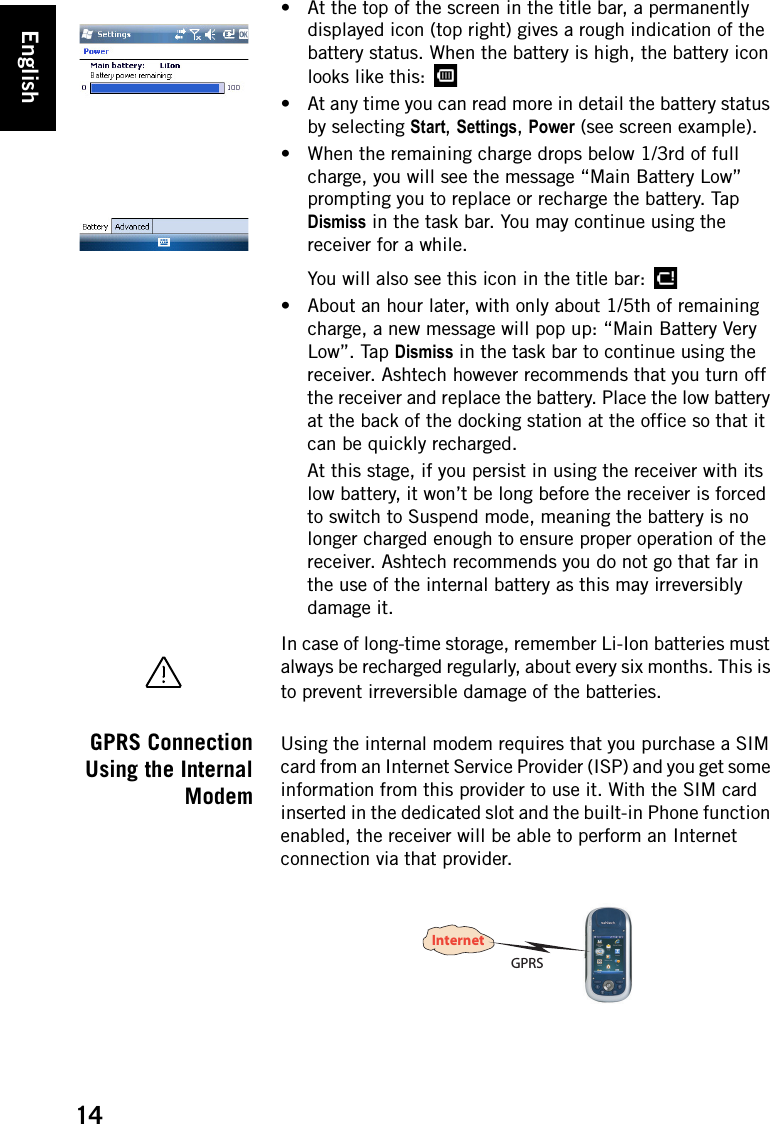
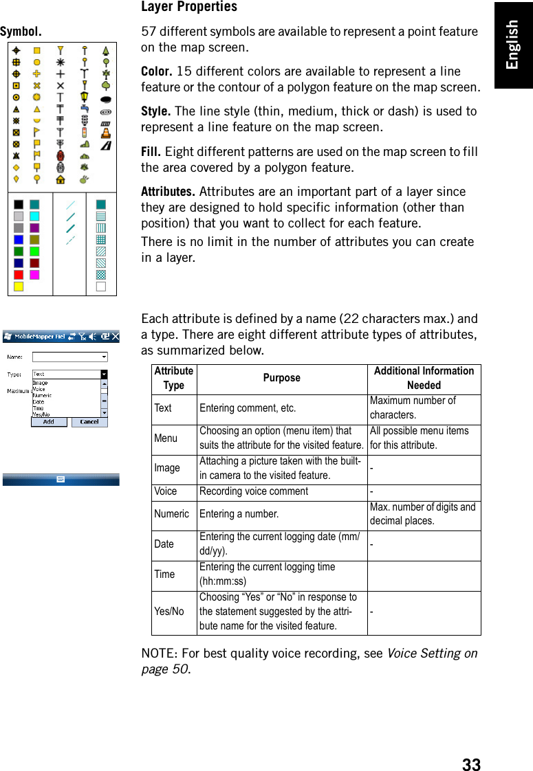
![English2First-Time UseUnpacking Open the receiver box and unpack the following items:• Receiver• Battery• Docking station• Universal AC adapter•USB cableCharging theBattery for the FirstTimeThe fastest way to charge the battery before first use is to plug it directly onto the back of the docking station and leave it there for less than 4 hours until it’s fully charged. Follow the instructions below.• Prepare the AC adapter: – Remove the protective cover [1] by pushing the button then sliding the cover forward.– Choose the plug that fits your country’s AC outlet standard (see [2]) and slide it into the AC adapter [3}. (A “click” must be heard when fully inserted.)– Connect the AC adapter to an electric outlet.• Put the docking station [4] on a horizontal plane.[1][2][3][5][4][6][7]](https://usermanual.wiki/TRIMBLE-EUROPE/802111A.user-manual-1-of-2/User-Guide-1379235-Page-6.png)
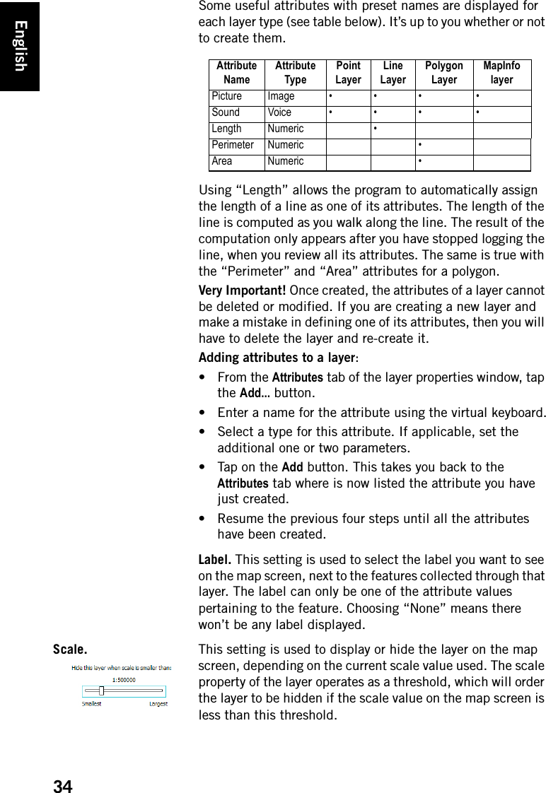
![English3• Connect the output cable [5] of the AC adapter to the docking station.• Insert the battery [6] vertically, label inwards, into the slot located at the back of the docking station.The light indicator [7] turns red, meaning the battery is being charged.• When the light indicator [7] turns green, this means the battery is fully charged and you can remove it from the docking station.Inserting theBattery Into theReceiverWhen the battery has been charged, do the following:• Turn over the receiver and rotate the finger screw counter-clockwise a quarter turn and pull the trap door open.• Insert the battery as shown. The label must be outwards and the right way up.• Put the trap door back into place by first inserting the two clips located at the top of the trap door.• Then push the door against the case and rotate the finger screw clockwise by one-quarter turn for a secure and sealed closure. Turning theReceiver OnPress the Power button [8] until the screen lights up.Then let the receiver run its boot sequence. Wait until the screen displays the Windows Mobile 6.5 Start screen.[8]](https://usermanual.wiki/TRIMBLE-EUROPE/802111A.user-manual-1-of-2/User-Guide-1379235-Page-7.png)
![English6enough satellites are tracked, you can start using your receiver and run your application software.Switching toSuspend ModeSwitching the receiver to Suspend mode is the right thing to do when you need to make a short pause in your work. In Suspend mode, the receiver is idle, using the minimum of energy required to save the use context. To switch to Suspend mode, just press briefly on the Power button [8].To wake up the receiver, hold the same button pressed ntil the screen wakes up. This will instantly restore the use context in which the receiver was before entering the Suspend mode. Turning theReceiver OffAfter you have finished your field work, turn off your receiver by holding the Power button [8] pressed until the message “Saving Parameters..” is displayed on the screen.The power shutdown will be effective after about 25 seconds. Tapping OK in the upper-right corner of the screen will not affect the progress of the power shutdown sequence but simply close the message window. There is indeed no way of shortening or canceling the power shutdown sequence.[8]](https://usermanual.wiki/TRIMBLE-EUROPE/802111A.user-manual-1-of-2/User-Guide-1379235-Page-10.png)
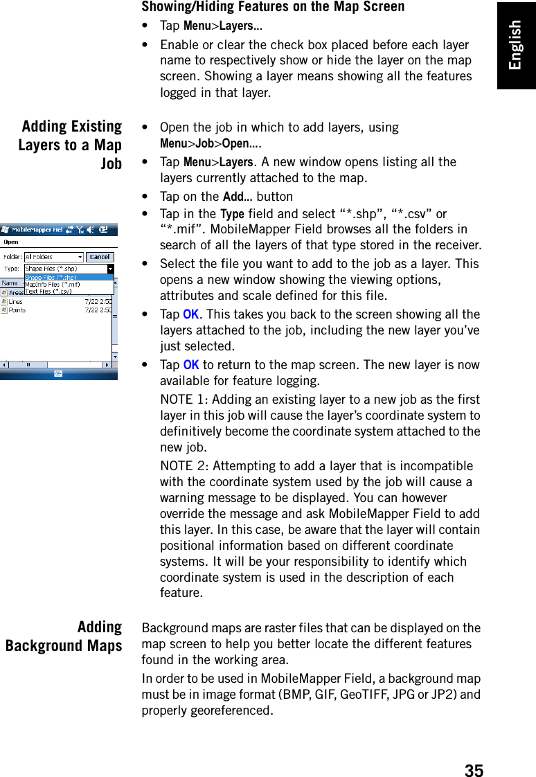
![English7System DescriptionReceiver FrontViewDisplay ScreenThe display screen [1] is a 3.5-inch QVGA color touch screen (240 x 320 pixels).Keypad, Scroll and Enter ButtonsThe keypad [2] consists of the following buttons: The Enter button [3] is used to accept highlighted input and initiate various functions.The Scroll button [4] is the ring around the Enter button. It is used to move the cursor on the screen, from one data field to the next on a parameter screen, from one option to another in a menu, from one geographical location to another on a map screen.Stylus and Stylus HolderThe stylus [5] can be used to work directly from the touch screen. When not used, the stylus can conveniently be stored in the receiver by inserting it into the dedicated holder [5]. Built-in GNSS AntennaThe receiver incorporates a built-in antenna [6]. The receiver should be held properly to optimize satellite reception. MicrophoneA microphone is used by the voice recorder. Keep the small aperture [7] clear when recording a vocal comment. [6][7][2][1][8][5][3] [4][9]Button FunctionThe keypad includes two of these buttons, one on the right, the other on the left.Each of them is a convenient alternative to tapping on the functions appearing just above in the task bar at the bottom of the screen (e.g. Menu, Log, etc.). These buttons are active only for those software applications specifically designed to use them.Use this button to enlarge the map displayed on the screen (zoom in).Use this button to reduce the map displayed on the screen (zoom out).In some software applications, use this button to cancel the last action performed or return to the previous screen.Use this button to show or hide the virtual keyboard on the screen.](https://usermanual.wiki/TRIMBLE-EUROPE/802111A.user-manual-1-of-2/User-Guide-1379235-Page-11.png)
![English8Built-in GSM Antenna[8]: Location of the built-in GSM antenna used for mobile communications.Built-in Bluetooth Antenna[9]: Location of the built-in Bluetooth antenna for wireless communication with nearby Bluetooth-fitted equipment.Receiver RearViewCamera LensKeep the camera lens [10] clear when taking pictures or recording videos. LoudspeakerAs a multi-media device, the receiver includes a high-quality loudspeaker [11], which can be used by any voice-based software application.Battery CompartmentThe receiver makes use of a rechargeable battery pack. Loosen the quarter-turn finger screw [12] to access the battery compartment [13],Receiver SideView (Left)Power Button• With the receiver off, pressing the Power button [14] briefly will turn on the receiver.• After the receiver has completed the boot sequence, another short press on the Power button will put the receiver in Suspend mode. Please refer to Power Modes on page 12 for more information on the Suspend mode.• To quit the Suspend mode, hold the Power button pressed for a few seconds until the screen wakes up. The receiver will then restore the context in which it was before being switched to Suspend mode.• With the receiver on, holding the Power button pressed for about 3 seconds will result in a receiver being turned off after about 30 seconds. In the sequence before effective receiver shutdown, the screen will display the message: “Saving Parameters...”. [10][12] [13][11][17][14][16][15]](https://usermanual.wiki/TRIMBLE-EUROPE/802111A.user-manual-1-of-2/User-Guide-1379235-Page-12.png)
![English9Power & Battery LEDThe three-color LED [15] gives indications on the receiver power status, and on the battery state, in relation with the use of the docking station. Please refer to LED Indicator on page 13 for more information on the LED indications. SD Card SlotGives access to an SD card slot [16], protected by a rubber flap. Use a finger nail or the tip of a pen to open the flap. Whenever possible, keep the flap close.Inserting an SD card: Push the SD card in until you hear a “click”.Removing an SD card: Push a bit further in and let go.External Antenna InputUse the external antenna input [17] to connect an external antenna to the receiver. When an external antenna is connected, the built-in antenna is automatically disconnected from the receiver input.The antenna input connector is protected by a rubber flap.Warning! Always keep the flap close when no external antenna is used.Receiver BottomViewPower/Data ConnectorThis connector ([18]) is used to connect the receiver to the docking station. This is achieved by simply inserting the receiver in an almost vertical position into the docking station. A secure connection is obtained once the receiver naturally rests on the docking station.There is also a threaded hole in the middle of the connector allowing you to secure the connection of the POGO cable to the receiver. Docking Station The docking station basically is a holder for the receiver. It may be used at the office for various and combined purposes:• As a safe and convenient tool for temporary receiver storage. The receiver is held firmly minimizing the risk of fall or scratches. • As a battery charger once powered by the AC adapter. The docking station can charge the battery inserted in the [17][14][16][15][18]](https://usermanual.wiki/TRIMBLE-EUROPE/802111A.user-manual-1-of-2/User-Guide-1379235-Page-13.png)
![English10receiver as well as an additional battery placed at the back of the docking station.When two batteries are charged simultaneously, fast charging (< 4 hours) is for the battery in the receiver and slow charging (about 11 hours) for the spare battery located at the back of the docking station.Charging for the spare battery switches to fast charging once the receiver battery is fully charged or the receiver is removed from the docking station.• As an interface with a computer for office work, using a serial data line and Microsoft ActiveSync.Top ViewThe top view of the docking station shows the slot [19] in which to insert the receiver from above the docking station. At the bottom of the slot is the 16-contact connector [20]. When resting on the docking station, the receiver is automatically powered from the AC adapter (if connected) and the charging status of its internal battery tested.[19][20]](https://usermanual.wiki/TRIMBLE-EUROPE/802111A.user-manual-1-of-2/User-Guide-1379235-Page-14.png)
![English11Rear ViewThe following elements can be found at the rear of the docking station:• Back slot [21] for charging a second battery• Charging indicator [22] for back slot:– Steady red: Battery charging in progress– Steady green: Battery fully charged– Off: No battery connected– Blinking red, every second: Battery internal temperature exceeds upper limit. Charging suspended until temperature is back to normal. If persisting, remove battery and resume charging later. If this occurs several times with the same battery, consider changing the battery. Dispose of the battery according to regulations. • Mini USB connector [23]: Use this connector to let the receiver communicate with your computer through Microsoft ActiveSync. • USB connector [24], Use this connector to plug a USB key.• RS232 SubD 9-C connector [25]: Use this port to connect the receiver to an external device.• Power input [26]. Connect the output of the AC adapter to this input.[21] [22][23] [24] [25] [26]](https://usermanual.wiki/TRIMBLE-EUROPE/802111A.user-manual-1-of-2/User-Guide-1379235-Page-15.png)
![English13LED Indicator The tables below summarize the different statuses reported by the Power/Charging LED [1]:Internal Battery When used in the field with its internal battery, the receiver will automatically inform you of the battery discharging status as follows:Table 1. Standalone ReceiverPower ModeLEDIndicationOn Green a few seconds at power on, then off.Off OffSuspend Green flash every 5 seconds.[1]Table 2. Receiver on Powered Docking Station, Normal StatusesLED Indication Power Mode Internal Battery StatusSteady red On or off ChargingSteady red with green flash every 5 seconds Suspend ChargingSteady green On, off or Suspend Charge completeTable 3. Receiver on Powered Docking Station, Abnormal StatusesLED IndicationPower ModeInternal Battery Status CommentBlinking red at 1-sec. time interval On or offBattery charging suspended because battery temperature too high.This should be a temporary situation. Charging will be resumed as soon as the temperature drops below the upper limit. If a persisting sit-uation, consider using a new battery and disposing of that one.Blinking green then orange at 1-sec. time intervalOn or offCharge complete, battery tempera-ture too high.Remove the receiver from the docking station. The bat-tery may be suspect. If this happens later with the same battery, consider using a new battery and disposing of that one.](https://usermanual.wiki/TRIMBLE-EUROPE/802111A.user-manual-1-of-2/User-Guide-1379235-Page-17.png)
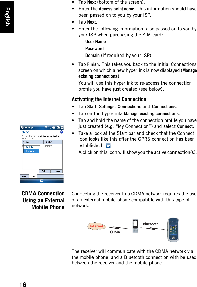
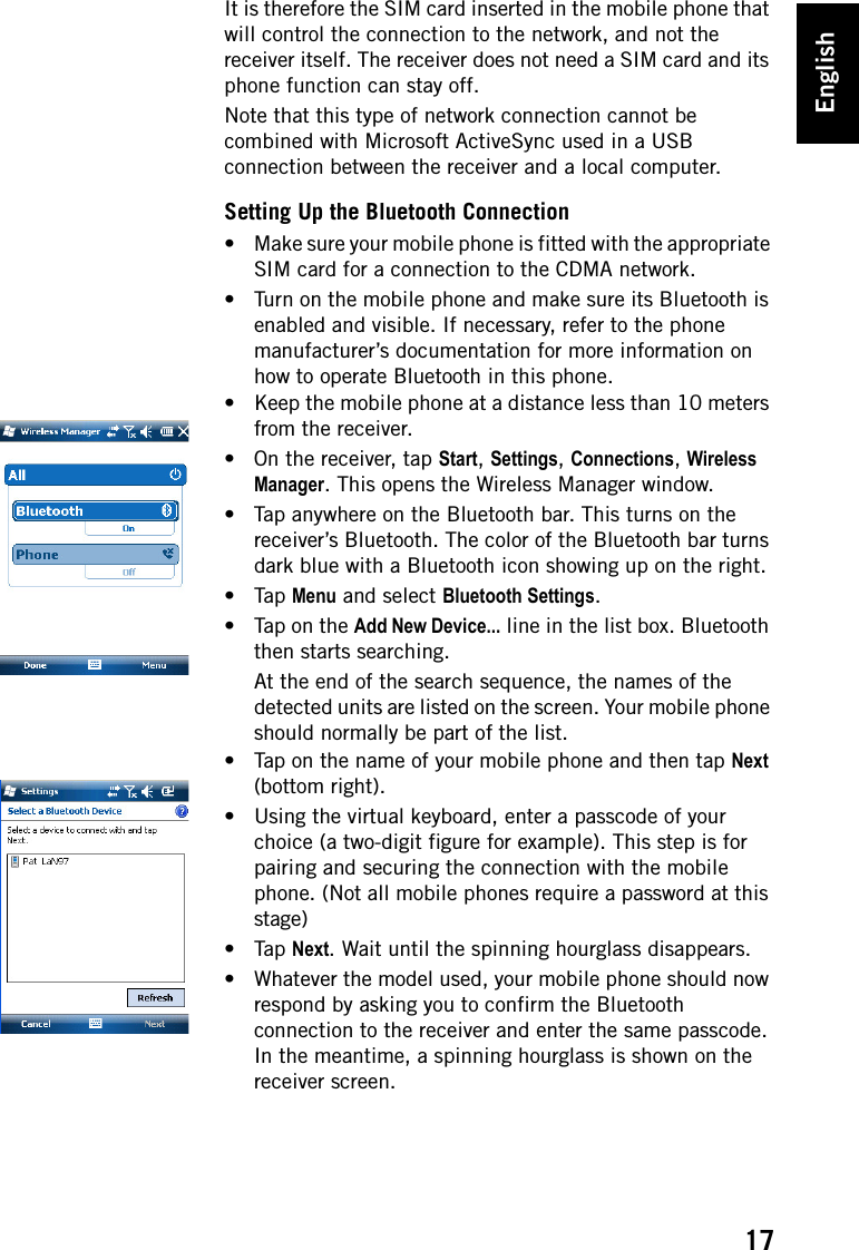
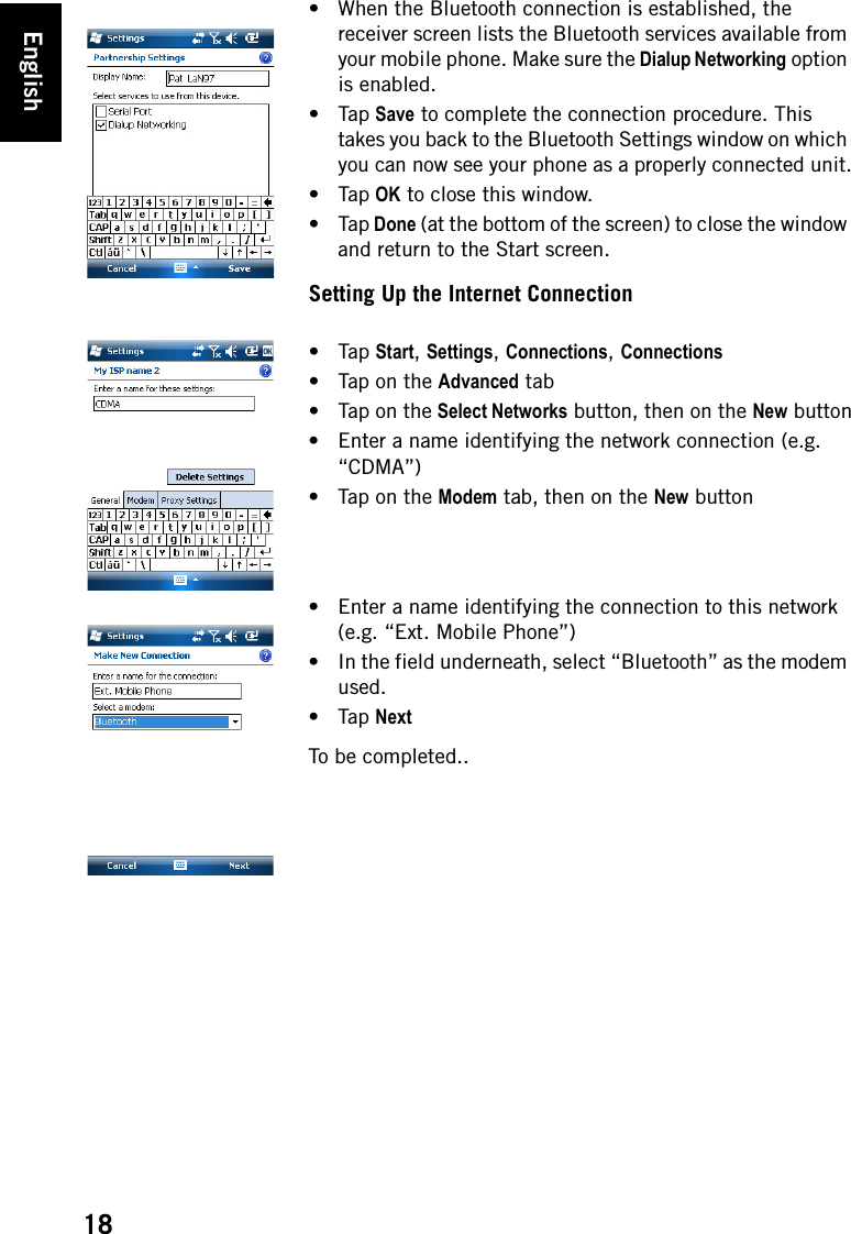
![English15Inserting a SIM CardRemove the battery door and the battery to access the SIM card holder. Refer to the figure below to insert the card. The holder should be opened before you can place the SIM card. Make sure you properly lock the SIM card holder before putting back the battery and locking the battery door.Enabling the Phone Function•Tap Start, Settings, Connections, Wireless Manager. This opens the Wireless Manager window.• Tap anywhere on the blue Phone bar. This turns on the Phone function. The color of the Phone bar turns dark blue with a phone icon showing up on the right.•Tap Done (at the bottom of the screen) to close the window and return to the Start screen.Setting the GPRS Connection•Tap Start, Settings, Connections and Connections.• Tap on the hyperlink: Add a new modem connection.• Name the new modem connection you are creating.• Select “Cellular Line (GPRS)” from the Select a modem field.[1] [2] [3][4][5]](https://usermanual.wiki/TRIMBLE-EUROPE/802111A.user-manual-1-of-2/User-Guide-1379235-Page-19.png)
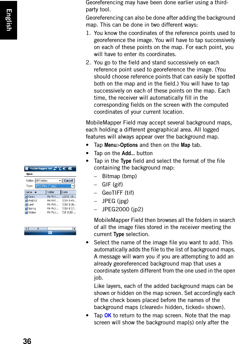
![English25Description of the MobileMapper Field Main Window• [1]: Number of satellites currently used in position computation; current value of PDOP; “DGPS” when the receiver is operating in SBAS differential mode; and “REC” if the raw data logging option is unlocked and active. This information line will not appear until the receiver can determine its own position.• [2]: This symbol shows your current position. The long axis of the symbol points in your last walking direction.• [3]: Current zoom setting. The current value of scale is provided, based on the currently selected unit.• [4]: Current position of the receiver (no coordinates displayed if the receiver has not determined its position yet).• [5]: Log button. Use this button to log features. The button is grayed until GPS positions are computed and a layer is added to the open job. You can use either the on-screen Log button or the LOG key on the keyboard to access the Log function.• [6]: Button used to show or hide the virtual keyboard. When the keyboard is displayed, the up arrow on the right of the button allows you to change keyboard settings or options.• [7] Menu button. Gives access to the MobileMapper Field function menu. You can use either the on-screen Menu [1][2][3][4][5] [7][9][10][6][8][11][12]](https://usermanual.wiki/TRIMBLE-EUROPE/802111A.user-manual-1-of-2/User-Guide-1379235-Page-29.png)
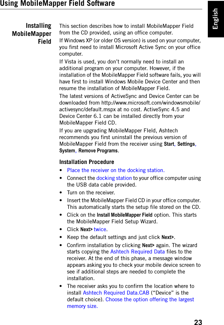
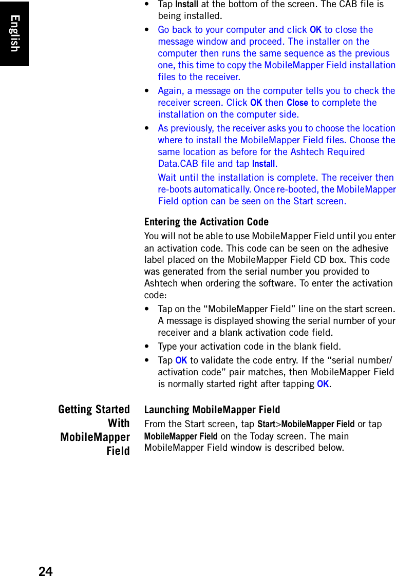
![English26button or the MENU key on the keyboard to show or hide the function menu.• [8]: Area showing a map of the working site (map screen).•[9]: Battery status• [10]: Volume setting• [11]: Phone status•[12]: Connectivity status.Dragging the Map on the ScreenUse one of the following two methods. • Press the ESC key to move the triangle symbol representing your current position back to the center of the map screen. Following this action, the whole screen is updated to reflect the map shift.• Drag the stylus in the desired direction.Setting Units, Antenna Height, PDOP Max. Background Maps and View Options1. Tap Menu>Options.... A new screen is displayed on which you can choose the measurements units:•Distance units: Choose between kilometers/meters or miles/feet.Menu Option FunctionPause Use this option to pause the current feature logging.Stop Use this option to stop the current feature logging.Layers... Use this option to add, modify or remove layers.Find... Use this option to find a feature previously logged in the open job.Go To... Use this option to let MobileMapper 6 guide you to the selected target (a feature name or any coordinates).Zoom In Increases the scale of the map view by one step.Zoom Out Decreases the scale of the map view by one step.Job Gives access to job-related functions: New, Open (and Properties if a job is already open).OptionsAllows you to access the following settings: Units, Antenna, Recording, Map, View, E-compass, Filter and External Devices.StatusGives access to three tabs describing the current GPS reception status, in digital (Position) or graphical (Satel-lites, Signal) form. (In fact the GNSS Status function from the GNSS Toolbox.)About Displays the installed version of MobileMapper Field.Exit Quits MobileMapper Field.](https://usermanual.wiki/TRIMBLE-EUROPE/802111A.user-manual-1-of-2/User-Guide-1379235-Page-30.png)
![English54The different areas are described below:– [1]: Open/Create Map button– [2]: Menu bar– [3]: MAP filename and Layers list– [4]: Map screen showing the content of the open job, Also includes zoom buttons on the left and distance/angle/area tool buttons on the right.– [5]: Depending on what is currently selected in area [3], [4] or [6], this area shows job properties (coordinate system and units used), layer attributes and appearance, or raw data file properties (observation time span, etc.). When selecting a feature on the map screen, the sound and image attributes pertaining to the feature can be heard and viewed by clicking on the three dots button after the file path in the corresponding field. Clicking on this button will start your computer’s default editor used for respectively WAV and JPG files.[4][5][6][1][2][3]](https://usermanual.wiki/TRIMBLE-EUROPE/802111A.user-manual-1-of-2/User-Guide-1379235-Page-58.png)
![English55– [6]: Observation times covered by the raw data files added to the project. A green bar stands for a receiver raw data file, and a yellow bar, for a base raw data file.• Click and select Open. Browse to the folder containing your field data files.• Select the Map file and click Open. MobileMapper Office shows the content of the project in areas [3], [4] and [5] (see screen above).• Click on Add Rover Raw Data. Select the raw data file corresponding to the project (from the same folder as previously) and click Open. MobileMapper Office imports the GRW file and then shows the file properties in areas [5] and [6]:• Assuming you are working with a third-party reference station, click successively on Add Reference Raw Data then From Web. A new window then opens in which you have to indicate how you wish to search for the reference station you will use for post-processing your job.• Choose one of the following two search criteria:–Search up to x stations: Specify a preset number of stations you want to list before choosing one. All the listed stations will be the closest to your working area, but there is no range limit for these stations.–Search up to x km: Specify a limit of distance between your working site and the stations. The shorter the distance, the better the raw data from the station, but the smaller the number of stations that can potentially be used.• Click Search, then wait until the search is complete. At the end of the search, MobileMapper Field lists the stations meeting the search request.](https://usermanual.wiki/TRIMBLE-EUROPE/802111A.user-manual-1-of-2/User-Guide-1379235-Page-59.png)
![English56• Select the most suitable reference station, mainly according to the distance (baseline) to that station.• Click Download. MobileMapper Office imports the base raw data and then show its properties in areas [5] and [6].NOTE: Ashtech does not guarantee 100% quality results when using raw data files from reference stations that are situated beyond 200 km (125 mi) from your working area.• Click on Start Processing. MobileMapper Office post-processes the different files present in the project. At the end of the post-processing, the map screen graphically displays the post-processed, more-accurate position of each GIS feature.Additionally, MobileMapper Office adds a vector layer into the project. Each feature in the layer can be edited individually. Vector attributes include useful quality information about vector determination.The post-processed SHP files are automatically updated with the new positions and then saved. Beforehand, backup files (<layer_name>.bak.shp) are created preserving the original content of the <layer_name>.shp files. Being also SHP files, backup files can be added to the project as layers, allowing you to compare the results of the post-processing against the original positions of your features.NOTE: DXF job files, MIF and CSV layers are not supported in this version of MobileMapper Office.](https://usermanual.wiki/TRIMBLE-EUROPE/802111A.user-manual-1-of-2/User-Guide-1379235-Page-60.png)
![English61already been downloaded from the Internet or if they come from a reference station that is not connected to the Internet, like for example an Ashtech ProMark3 base. In either case, click on Add Reference Raw Data>From File and select the base raw data files.•Removing a layer from a map: Select the layer in area [3] on the screen and press the Del key or click on Remove Layer.•Recommendations on folders: Ashtech recommends you store all the files pertaining to a project in the same folder. By doing this, you will be able to open your Map files equally in your receiver and MobileMapper Office software without losing a single SHP layer.Post-ProcessingDemoClick on the diagram below to start a short demo on how to quickly post-process your field data files in MobileMapper Office. (Under Construction)](https://usermanual.wiki/TRIMBLE-EUROPE/802111A.user-manual-1-of-2/User-Guide-1379235-Page-65.png)