TSC Auto ID Technology 2008001 Printer with RFID Module User Manual 8 user manual
TSC Auto ID Technology Co., Ltd. Printer with RFID Module 8 user manual
UserManual.wiki
>
TSC Auto ID Technology
>
2008001 User Manual
User Manual
Navigation menu
Upload a User Manual
Namespaces
Wiki Guide
HTML
PDF
Info
Views
User Manual
Discussion / Help
Navigation
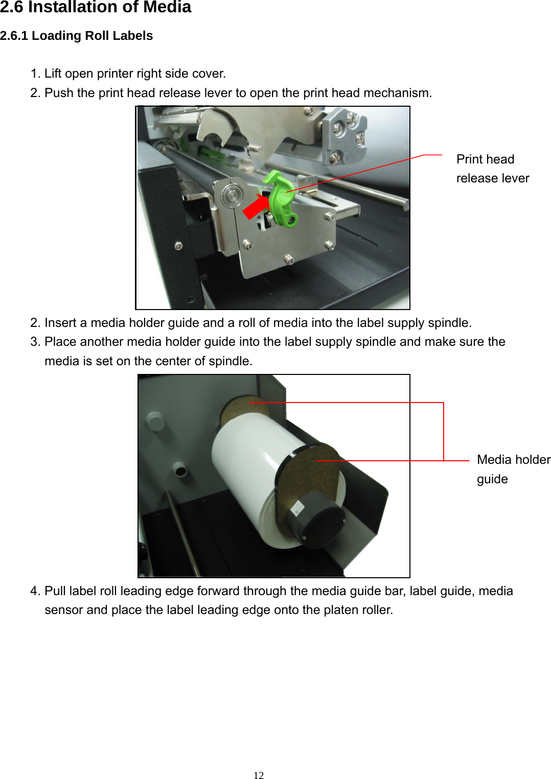
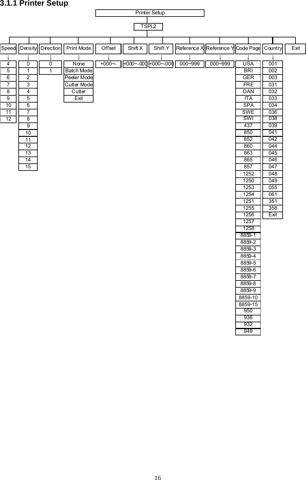
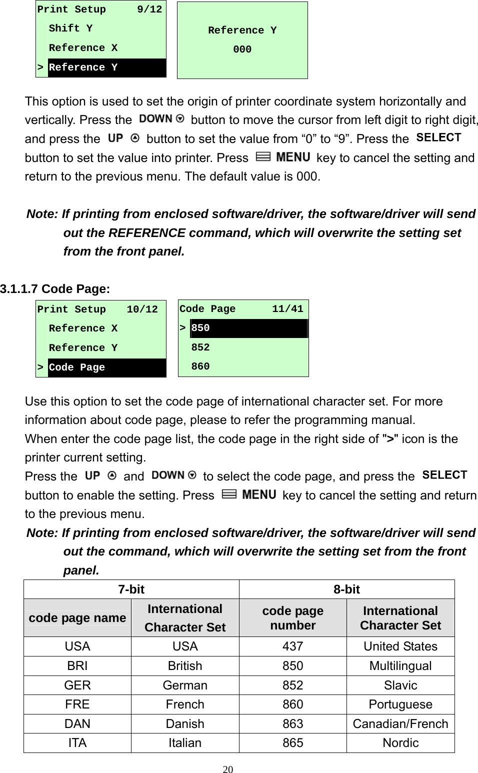
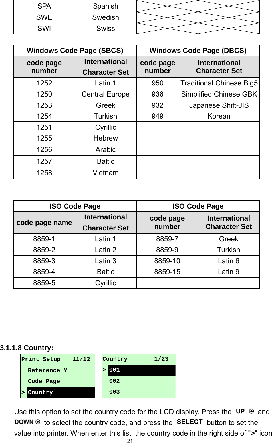
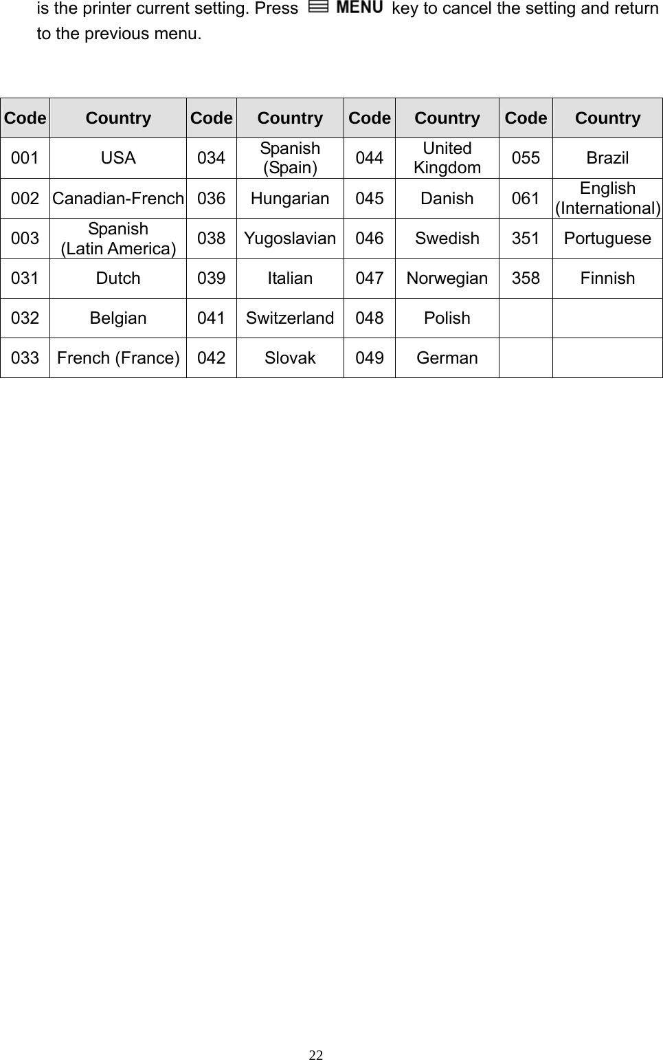
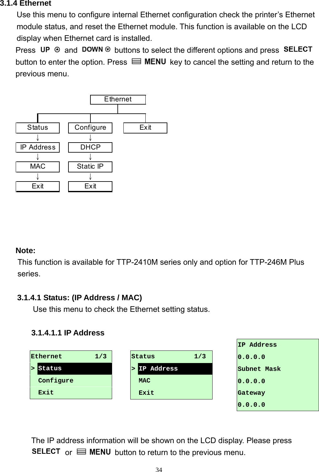
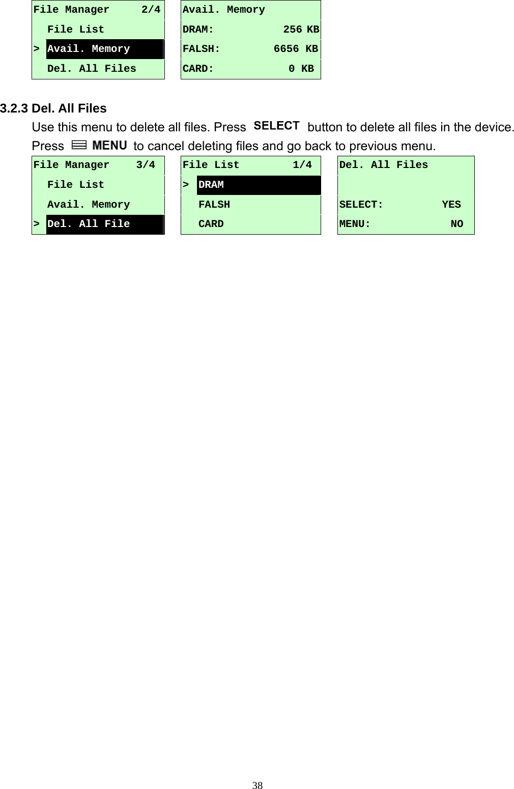
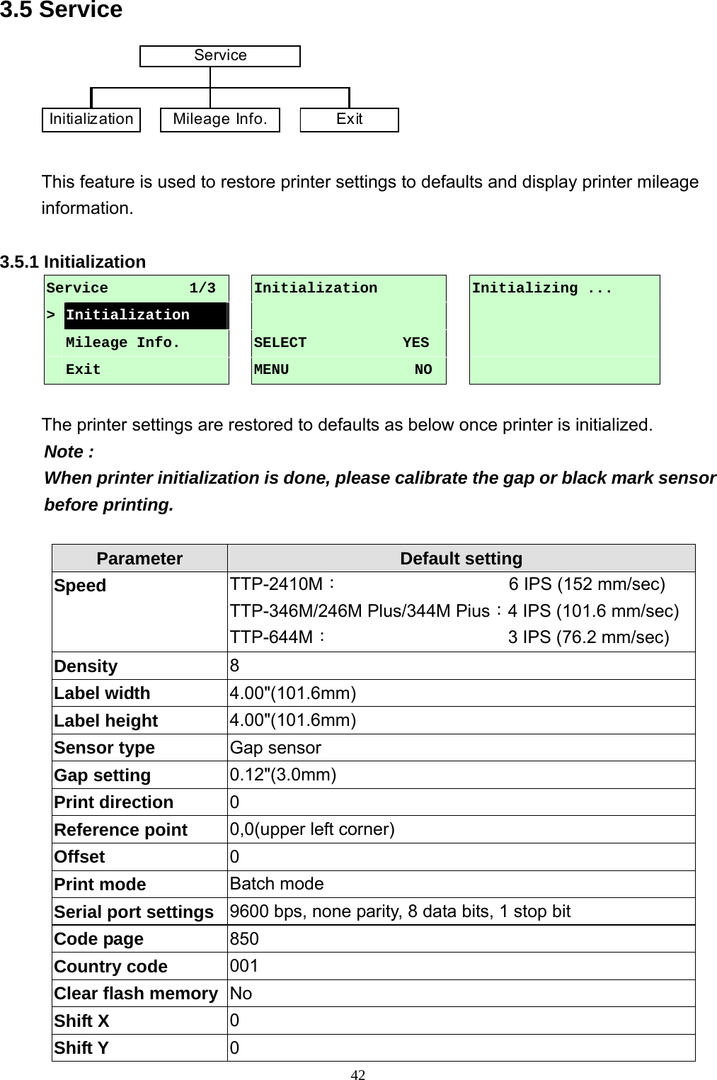
![233.1.2 Sensor ExitStatus CalibrationSensor 3.1.2.1 Status This function is available to check the printer’s sensor status. When enter the [Status] option, you will see following message. 3.1.2.2 Calibration This option is used to set the media sensor type and calibrate the selected sensor. We recommend to calibrate the sensor before printing when changing the media. Exit↓↓ ↓Gap Mode Bline Mode Cont. Mode↓↓ ↓Automatic Automatic AutomaticPre-Printed↓↓Manual Manual Manual↓↓ExitPre-Printed Exit↓ExitCalibration Paper Len. 812 Gap Size 24 Intensity 3 Ref. Level 512](https://usermanual.wiki/TSC-Auto-ID-Technology/2008001/User-Guide-995378-Page-27.png)
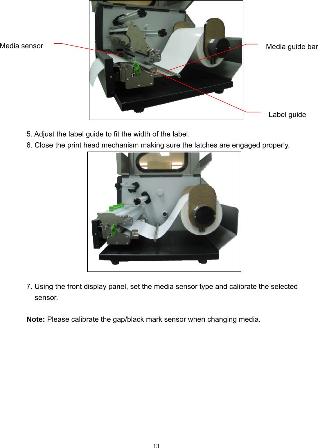
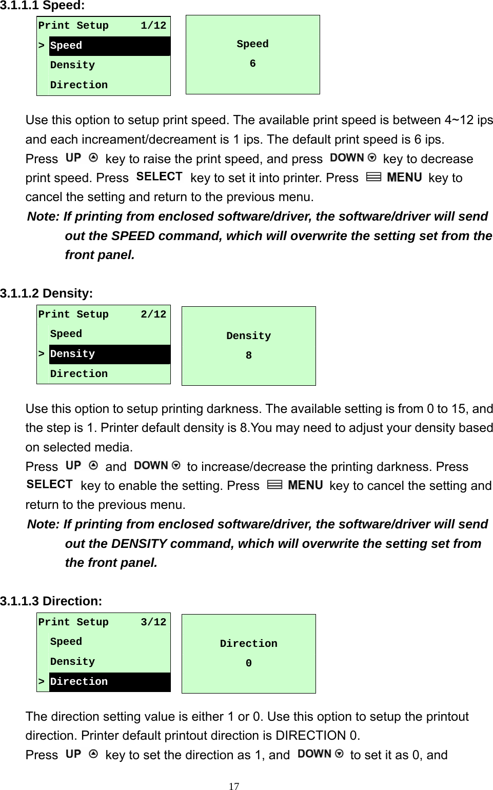
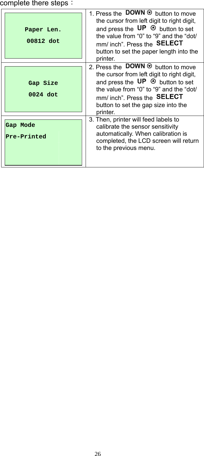
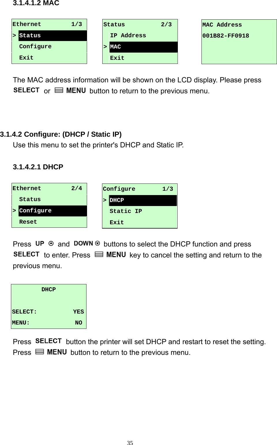
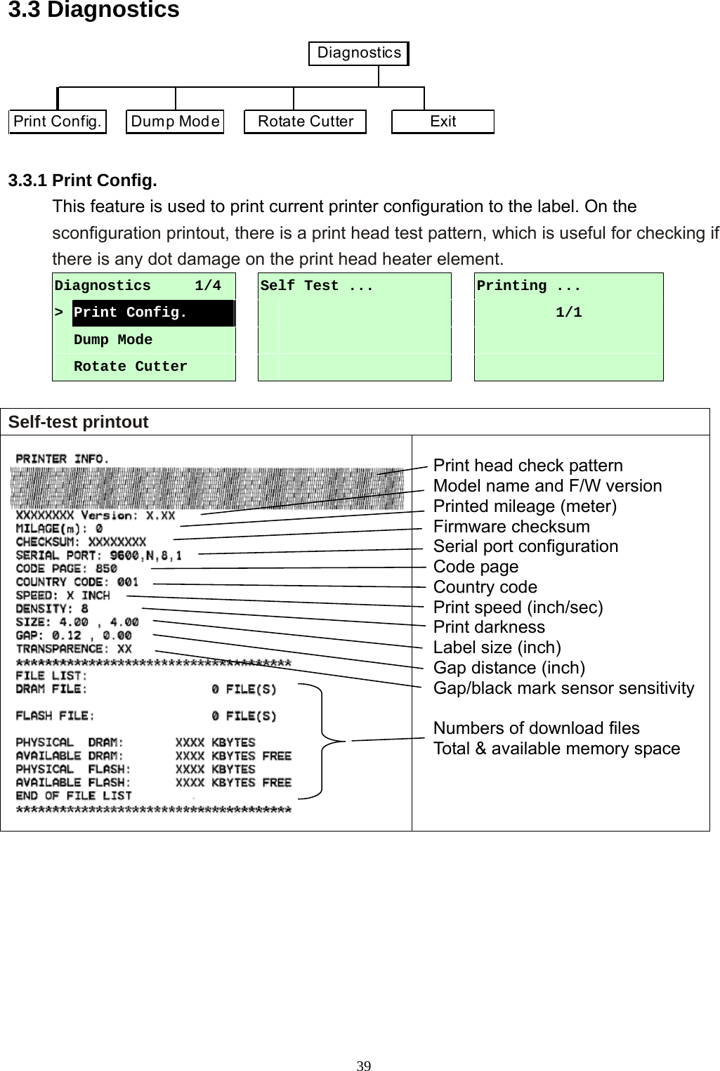
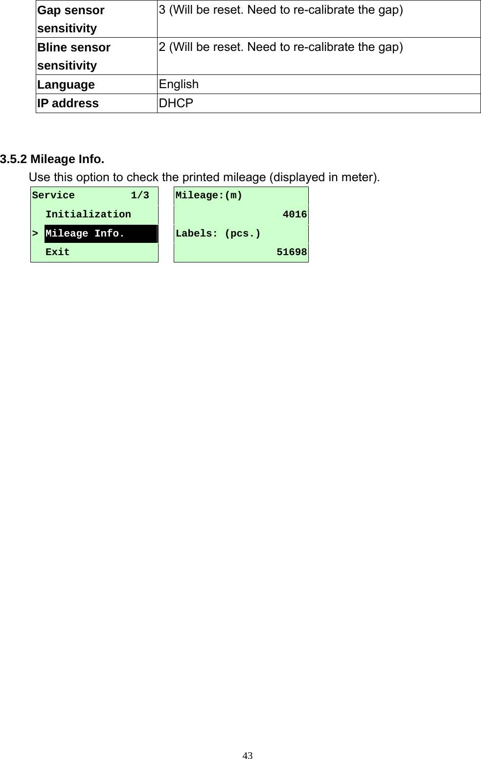
![24A. Gap Mode Press the and buttons to scroll the cursor to the media type and press the button to enter the sensor calibration mode. Note: If printing from enclosed software/driver, the software/driver will send out the GAP or BLINE command, which will overwrite the sensor type setting set from the front panel. A-1 Automatic When enter the [Automatic] option, you will see following message, and printer will feed 2 to 3 gap labels to calibrate the sensor sensitivity automatically. When calibration is completed, the LCD screen will return to the previous menu. A-2 Manual In case “Automatic” sensor calibration cannot apply to the media, please use “Manual” function to calibrate the gap sensor manually. When enter [Manual] option, you will see following message. Please complete there steps: Paper Len. 00812 dot 1. Press the button to move the cursor from left digit to right digit, and press the button to set the value from “0” to “9” and the “dot/ mm/ inch”. Press the button to set the paper length into the printer. Calibration 1/4 > Gap Mode Bline Mode Cont. Mode Gap Mode 1/4>Automatic Manual Pre-Printed Gap Mode Automatic Gap Mode 2/4 Automatic > Manual Pre-Printed](https://usermanual.wiki/TSC-Auto-ID-Technology/2008001/User-Guide-995378-Page-28.png)
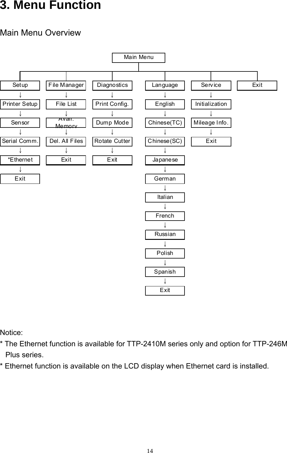
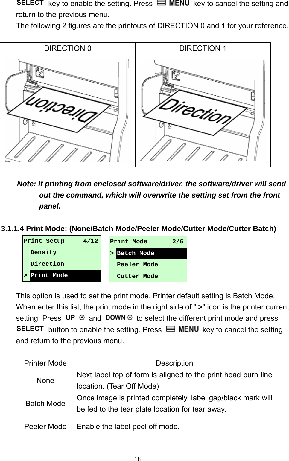
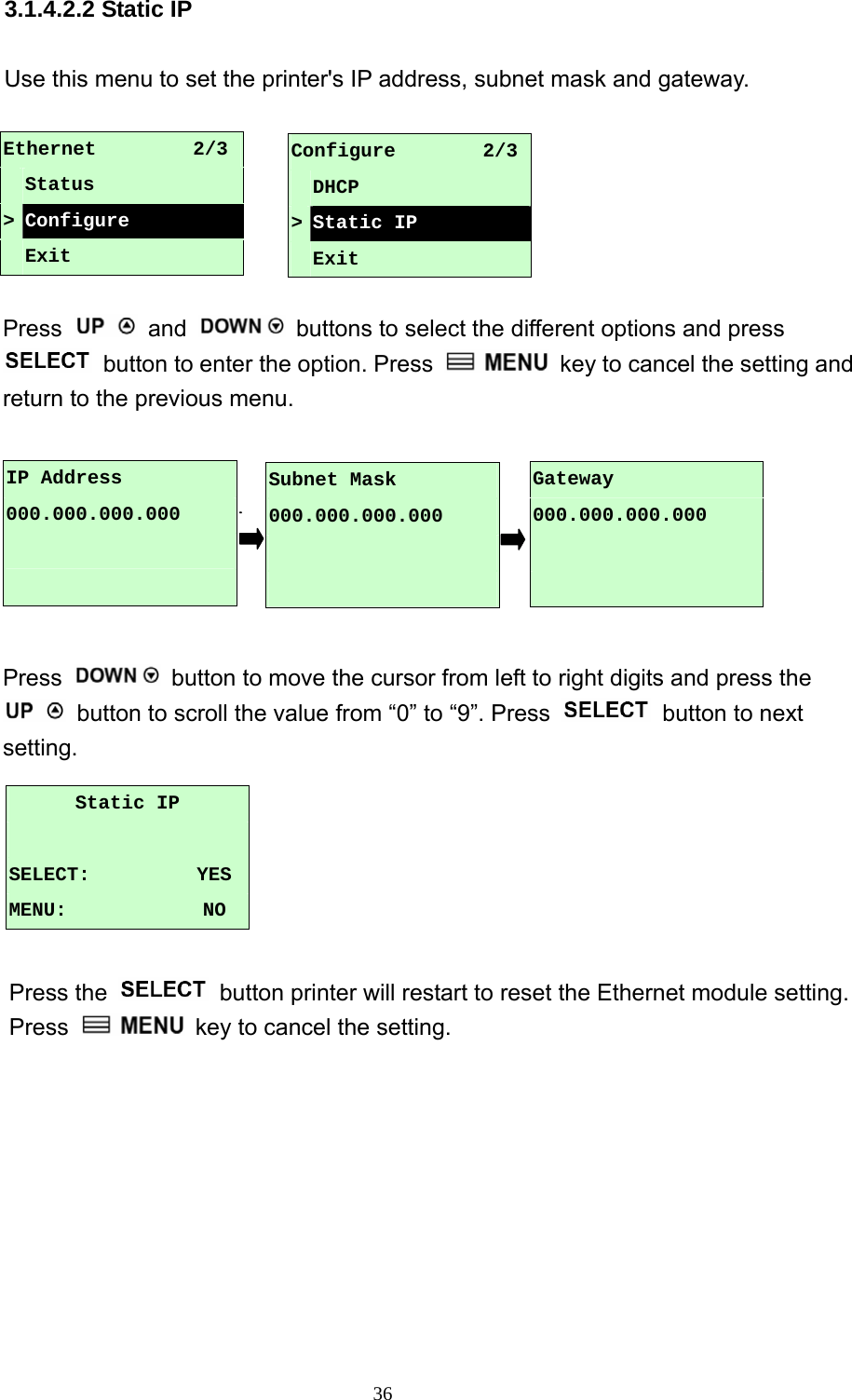
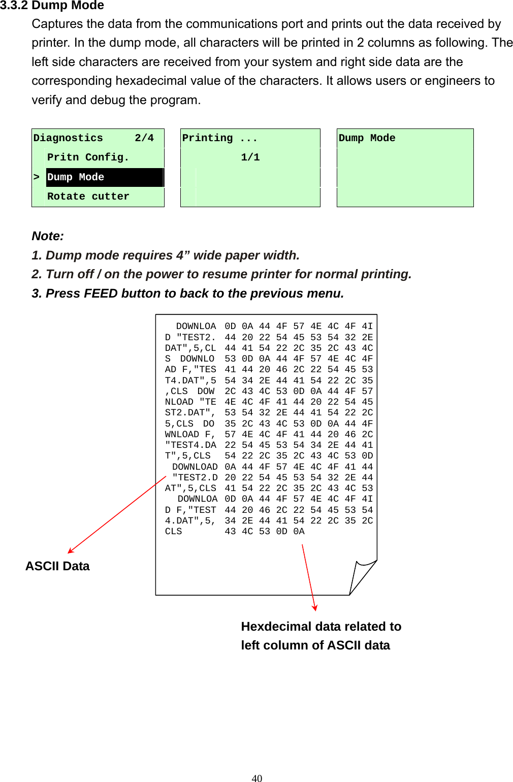
![25 Gap Size 0024 dot 2. Press the button to move the cursor from left digit to right digit, and press the button to set the value from “0” to “9” and the “dot/ mm/ inch”. Press the button to set the gap size into the printer. Gap Mode Scan Backing Intensity xRef. Level xxx3. Open the print head mechanism, put the label backing (liner) under the media sensor. Press the button to set the value into the printer. Gap Mode Scan Paper Intensity xRef. Level xxx4. Then, Put the label with liner under the media sensor. Press the button to set the value into the printer. Gap Mode Complete Intensity xRef. Level xxx5. The gap sensor calibration is complete. Press the button the LCD screen will return to the previous menu. A-3 Pre-Printed This function can set the paper length and gap size before auto-calibrate the sensor sensitivity. It can to get the sensor sensitivity accurately. When enter [Pre-Printed] option, you will see following message. Please Gap Mode 3/4 Manual > Pre-Printed Exit Media sensor Label backing (liner) Media sensor Label with liner](https://usermanual.wiki/TSC-Auto-ID-Technology/2008001/User-Guide-995378-Page-29.png)
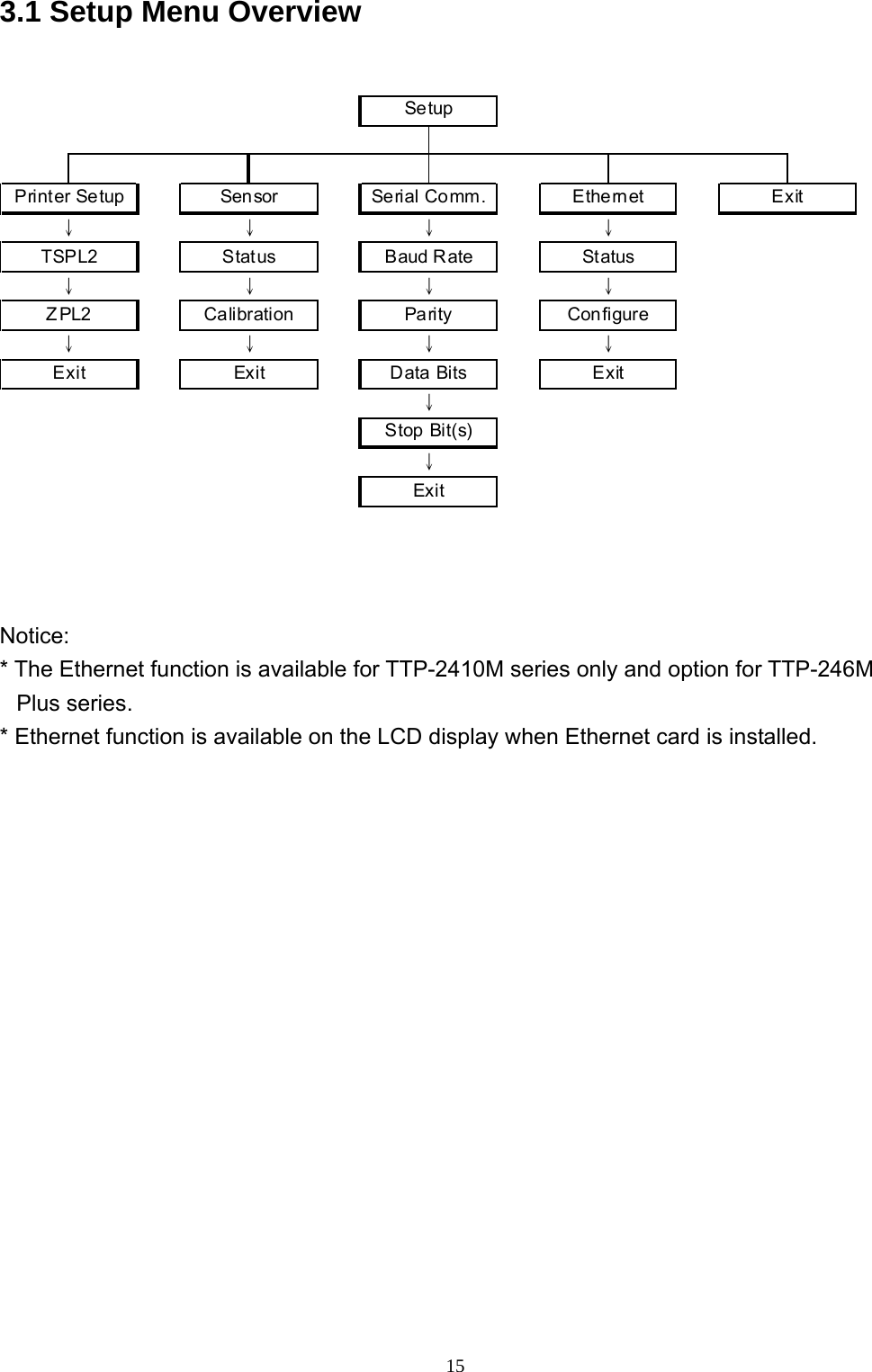
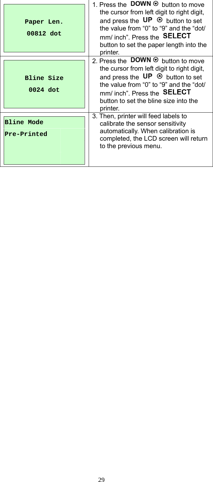
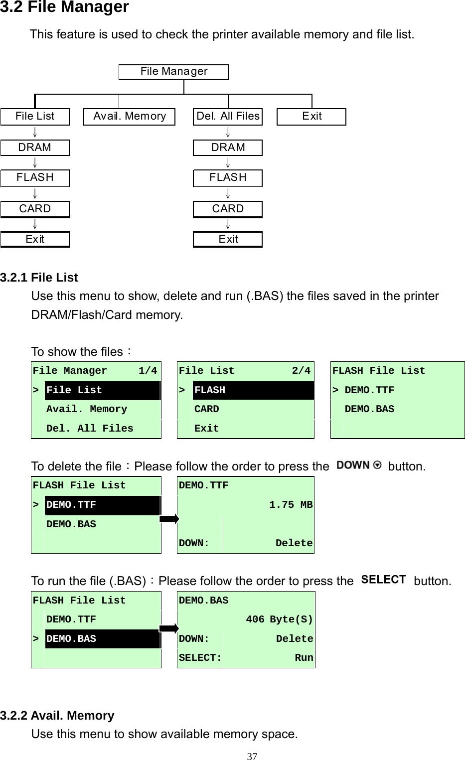
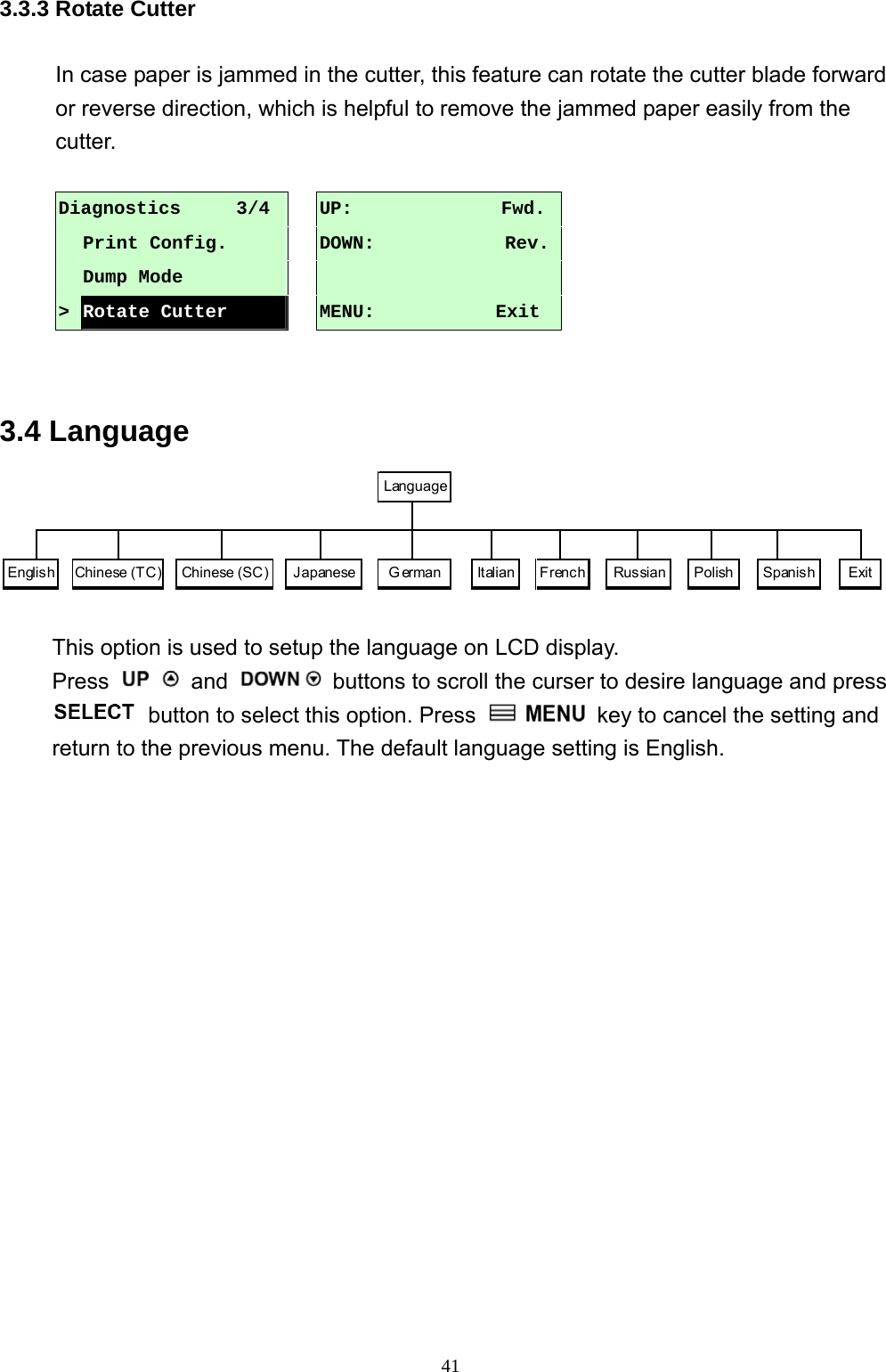
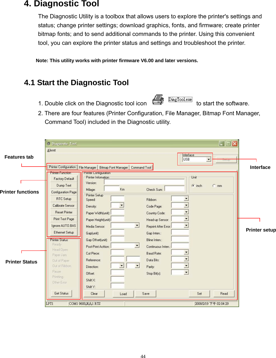
![27B. Bline Mode Press the and buttons to scroll the cursor to the sensor type. Press the button to enter the black-mark sensor calibration mode. B-1 Automatic When enter the [Automatic] option, you will see following message and printer will feed the black mark label to calibrate the sensor sensitivity automatically. When calibration process is completed, the LCD screen will return to the previous menu. B-2 Manual In case “Automatic” sensor calibration cannot apply to the media, please use “Manual” function to calibrate the bline sensor manually. When enter [Manual] option, you will see following message. Please complete there steps: Paper Len. 00151 dot 1. Press the button to move the cursor from left digit to right digit, and press the button to set the value from “0” to “9” and the “dot/ mm/ inch”. Press the button to set the paper length into the printer. Bline Size 0024 dot 2. Press the button to move the cursor from left digit to right digit, and press the button to set the value from “0” to “9” and the “dot/ mm/ inch”. Press the button to set the bline size into the printer. Calibration 2/4 Gap Mode > Bline Mode Cont. Mode Bline Mode 1/4 >Automatic Manual Pre-Printed Bline Mode Automatic Bline Mode 2/4 Automatic > Manual Pre-Printed](https://usermanual.wiki/TSC-Auto-ID-Technology/2008001/User-Guide-995378-Page-31.png)
![28 Bline Mode Scan Mark Intensity xRef. Level xxx3. Open the print head mechanism, put the black mark under the media sensor. Press the button to set the value into the printer. Bline Mode Scan Paper Intensity xRef. Level xxx4. Then, put the label without black mark under the media sensor. Press the button to set the value into the printer. Note: Normally, the value of “Ref. Level” for mark should be larger than paper for over 128. If the media sensor fails to do so, you have to manually change the Intensity by pressing and to reach the above value. Bline Mode Complete Intensity xRef. Level xxx5. The bline sensor calibration is complete. Press the button the LCD screen will return to the previous menu. B-3 Pre-Printed This function can set the paper length and gap size before auto-calibrate the sensor sensitivity. It can to get the sensor sensitivity accurately. When enter [Pre-Printed] option, you will see following message. Please complete there steps: Bline Mode 3/4 Manual > Pre-Printed Exit Media sensor Black markMedia sensor Label without black mark](https://usermanual.wiki/TSC-Auto-ID-Technology/2008001/User-Guide-995378-Page-32.png)
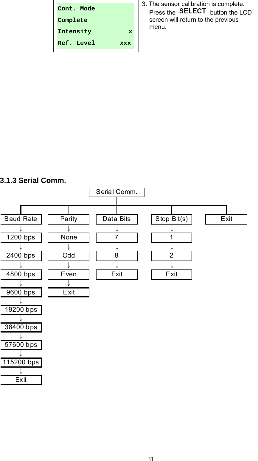
![30C. Cont. Mode Press the and buttons to scroll the cursor to the sensor type. Press the button to enter the black-mark sensor calibration mode. C-1 Automatic When enter the [Automatic] option, you will see following message and printer will calibrate the sensor sensitivity automatically. When calibration process is completed, the LCD screen will return to the previous menu. C-2 Manual In case “Automatic” sensor calibration cannot apply to the media, please use “Manual” function to calibrate the sensor manually. When enter [Manual] option, you will see following message. Please complete there steps: Cont. Mode Remove Label Intensity xRef. Level xxx1. Remove the continuous label. Press the button to set the value into the printer. Cont. Mode Scan Paper Intensity xRef. Level xxx2. Then, put the continuous label under the media sensor. Press the button to set the value into the printer. Calibration 3/4 Bline Mode > Cont. Mode Exit Cont. Mode 1/3>Automatic Manual Exit Cont. Mode Automatic Cont. Mode 2/3 Automatic > Manual Exit](https://usermanual.wiki/TSC-Auto-ID-Technology/2008001/User-Guide-995378-Page-34.png)
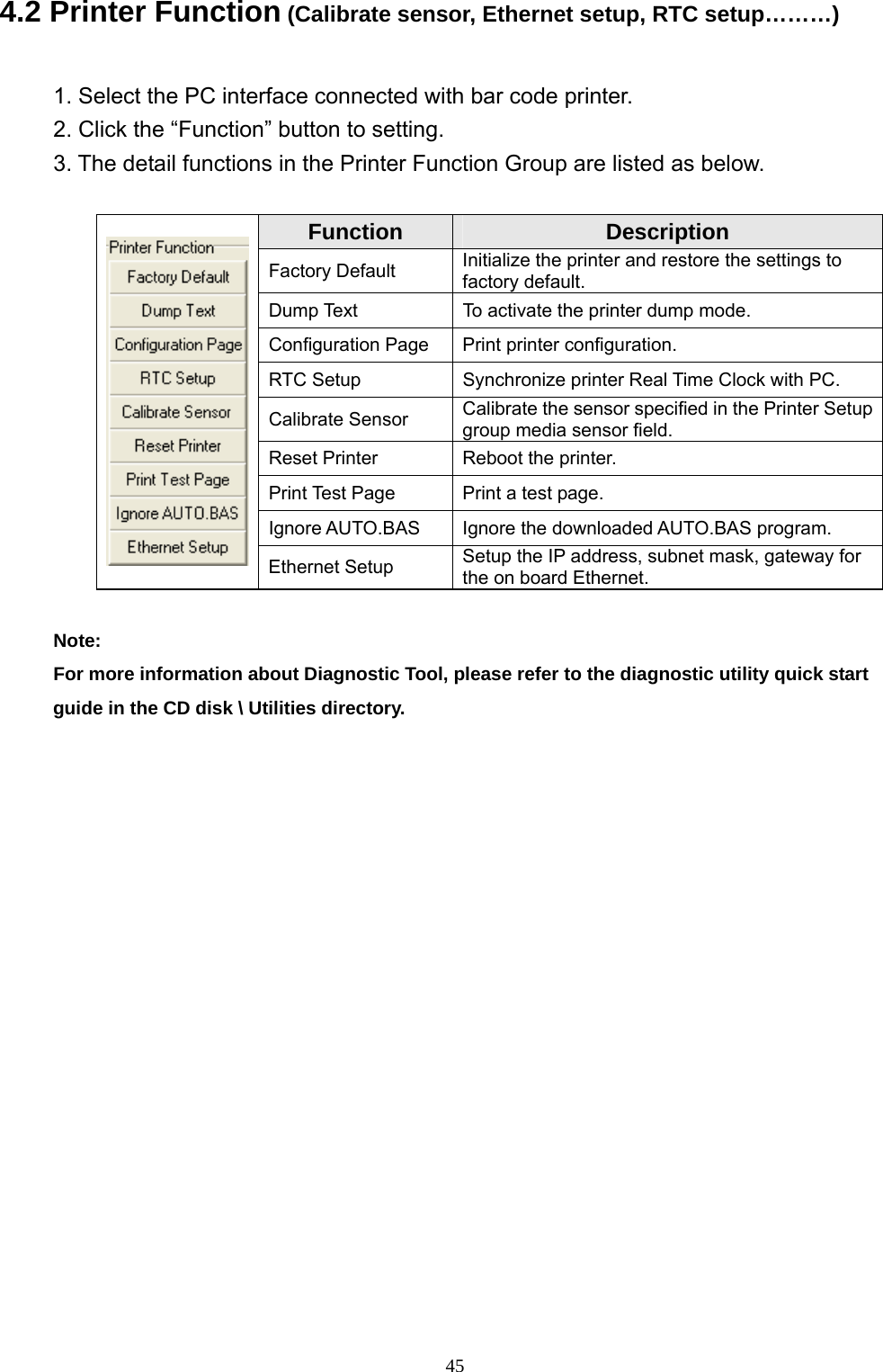
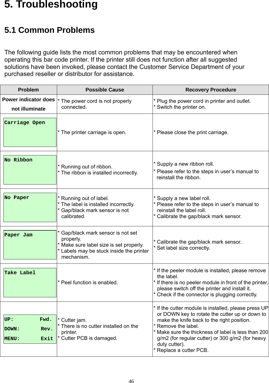
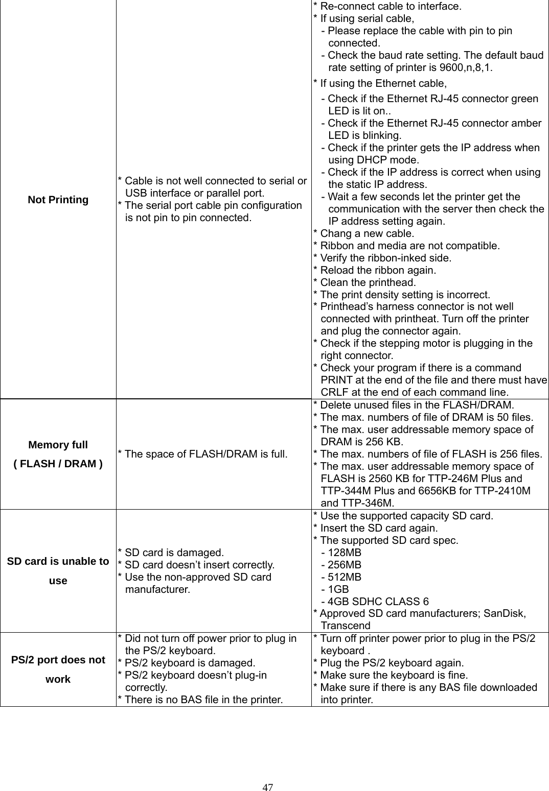
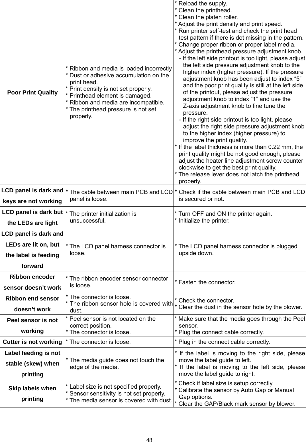
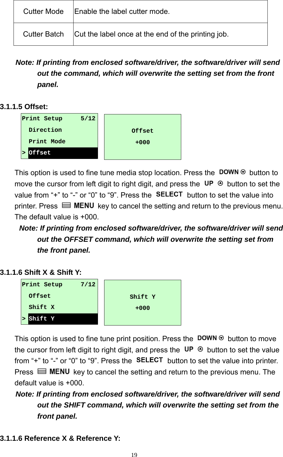
![49The printing position of small label is incorrect * Media sensor sensitivity is not set properly. * Label size is incorrect. * The parameter Shift Y in the LCD menu is incorrect. * The vertical offset setting in the driver is incorrect. * Calibrate the sensor sensitivity again. * Set the correct label size and gap size. * Press [MENU] [SELECT] x3[DOWN]x6 [SELECT] to fine tune the parameter of Shift Y.* If using the software BarTender, please set the vertical offset in the driver. The left side printout position is incorrect * Wrong label size setup. * The parameter Shift X in LCD menu is incorrect. * Set the correct label size. * Press [MENU] [SELECT] x 3 [DOWN] x 5[SELECT] to fine tune the parameter of Shift X. Missing printing on the left or right side of label * Wrong label size setup. * Set the correct label size. RTC time is incorrect when reboot the printer * The battery has run down. * Check if there is a battery on the main board. Multi interface board doesn’t work * The installation is incorrect. * Check if the board is plugged in the right connector. Power and Error LEDs are blinking fast * Power switch OFF and ON too fast. * Turn off the printer and wait all LEDs are dark, and turn on the printer again. Wrinkle Problem * Printhead pressure is incorrect. * Ribbon installation is incorrect. * Media installation is incorrect. * Print density is incorrect. * Media feeding is incorrect. * Please refer to the 5.2 chapter. * Please set the suitable density to have good print quality. * Make sure the label guide touch the edge of the media guide. Gray line on the blank label * The printhaed is dirty. * The platen roller is dirty. * Clean the printhead. * Clean the platen roller. Irregular printing * The printer is in Hex Dump mode. * The RS-232 setting is incorrect. * Turn off and on the printer to skip the dump mode. * Re-set the Rs-232 setting.](https://usermanual.wiki/TSC-Auto-ID-Technology/2008001/User-Guide-995378-Page-53.png)