TSC Auto ID Technology RFWKD WIFI Module User Manual
TSC Auto ID Technology Co., Ltd. WIFI Module Users Manual
UserManual.wiki
>
TSC Auto ID Technology
>
RFWKD User Manual
>
Users Manual
Contents
1.
Users Manual
2.
(RF-WKD) UserMan
Users Manual
Navigation menu
Upload a User Manual
Namespaces
Wiki Guide
HTML
PDF
Info
Views
User Manual
Discussion / Help
Navigation
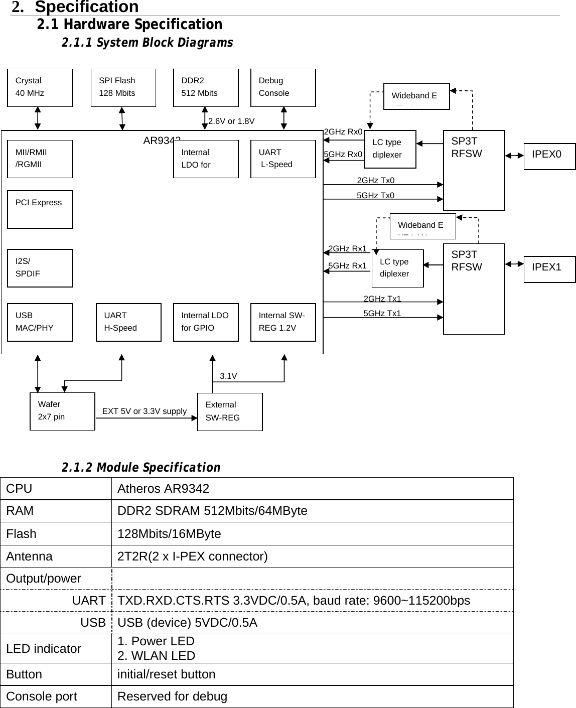
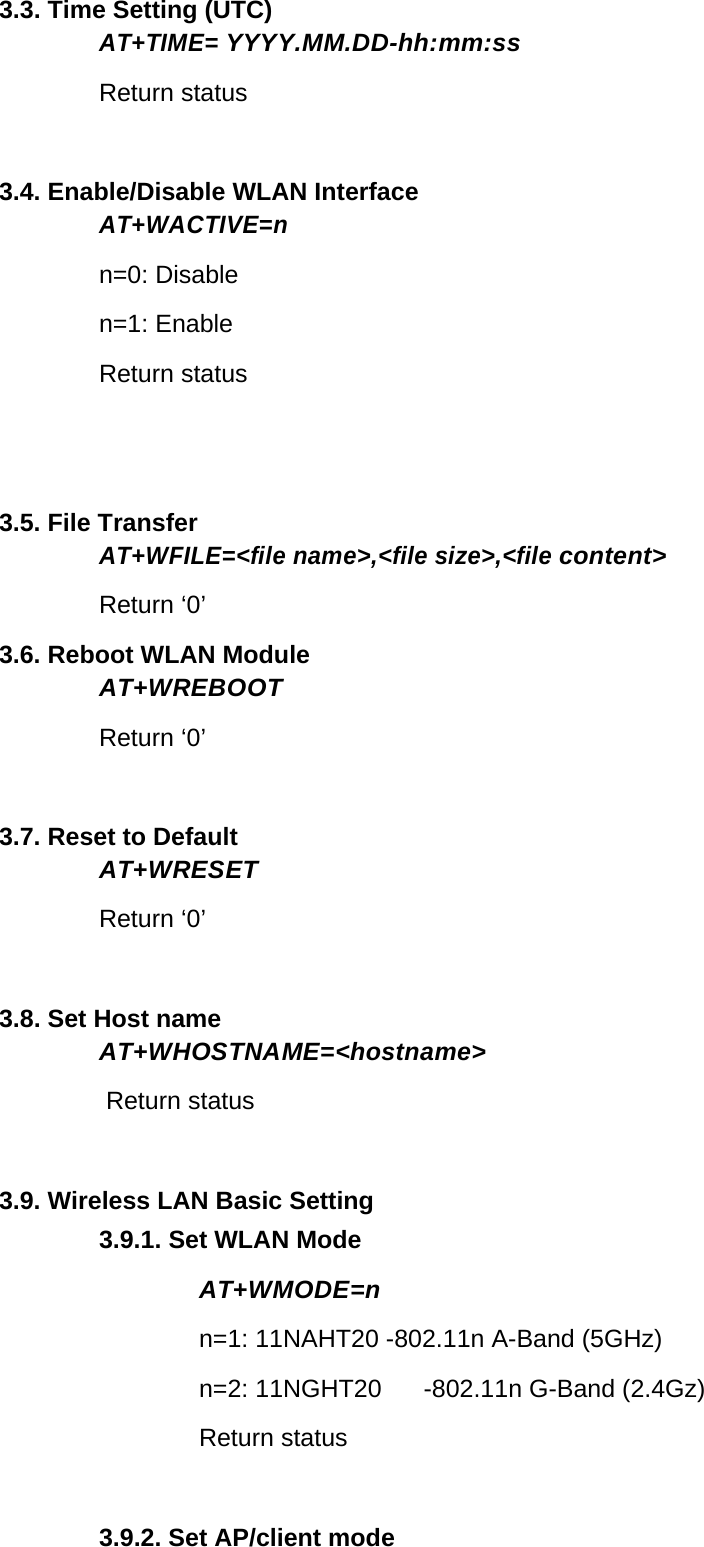
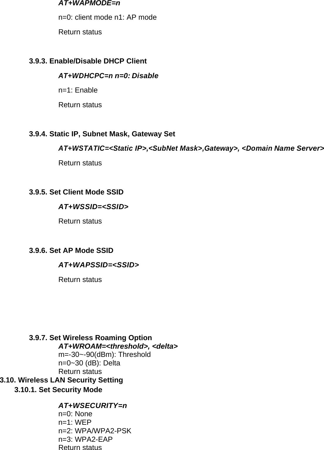
![4. Network command Format To ensure all transfers over UART are operating as expectation, each transfer is required to include the following fields: ● An Opcode which defines the specific operation, the operation may be different between the Printer and the Module. ● A transfer size designates the whole size of this transfer. Target should drop this transfer and acknowledge Initiator with error when received size is different to this value. * All the fields denoted in transfers are adhering to Network Byte Order (Big Endian). Transfer Commands: Printer Command Set: Data Write Command: This command provides function for Initiator to write data to Target. Initiator Request: Module Ready Signal: Module Request: *Version: String: [MAJOR NUMBER].[MINOR NUMBER].[BUILD NUMBER] AT Command: Printer can communicate AT command with Module in following format. Initiator Request: Target Response: Opcode Transfer size Data Checksum Value 0x1100 Size Data Reserved Size (Byte) 2 3 <16M 2 Opcode Transfer size F/W Ver. Checksum Value 0xFF00 Size Version* Reserved Size (Byte) 2 3 8 2 Opcode Transfer size Data Checksum Value 0x2000 Size AT command Reserved Size (Byte) 2 3 <16M 2 Opcode Transfer size Data Checksum Value 0x2000 Size AT Response Reserved Size (Byte) 2 3 <16M 2](https://usermanual.wiki/TSC-Auto-ID-Technology/RFWKD.Users-Manual/User-Guide-2517260-Page-15.png)