TSC Auto ID Technology RFWKD WIFI Module User Manual
TSC Auto ID Technology Co., Ltd. WIFI Module Users Manual
Contents
- 1. Users Manual
- 2. (RF-WKD) UserMan
Users Manual

USER’S
MANUAL
RF-WKD
Wi-Fi module

Copyright Information
©2014 TSC Auto ID Technology Co., Ltd,
The copyright in this manual, the software and firmware in the printer described therein are
owned by TSC Auto ID Technology Co., Ltd, All rights reserved.
Information in this document is subject to change without notice and does not represent
a commitment on the part of TSC Auto ID Technology Co. No part of this manual may be
reproduced or transmitted in any form or by any means, for any purpose other than the
purchaser’s personal use, without the expressed written permission of TSC Auto ID Technology
Co.

Agency Compliance and Approvals
FEDERAL COMMUNICATIONS COMMISSION INTERFERENCE STATEMENT
This equipment has been tested and found to comply with the limits for a Class B digital
device, pursuant to part 15 of the FCC Rules. These limits are designed to provide
reasonable protection against harmful interference in a residential installation. This
equipment generates, uses and can radiate radio frequency energy and, if not
installed and used in accordance with the instructions, may cause harmful interference to
radio communications. However, there is no guarantee that interference will not occur in a
particular installation. If this equipment does cause harmful interference to radio or television
reception, which can be determined by turning the equipment off and on, the user is
encouraged to try to correct the interference by one or more of the following measures:
-Reorient or relocate the receiving antenna.
-Increase the separation between the equipment and receiver.
-Connect the equipment into an outlet on a circuit different from that to which the receiver
is connected.
-Consult the dealer or an experienced radio/ TV technician for help.
CAUTION:
Any changes or modifications not expressly approved by the grantee of this
device could void the user's authority to operate the equipment.
This device complies with Part 15 of the FCC Rules. Operation is subject to the following
two conditions: (1) this device may not cause harmful interference, and (2) this device must
accept any interference received, including interference that may cause
undesired operation.
RF exposure warning
This equipment must be installed and operated in accordance with provided instructions
and the antenna(s) used for this transmitter must be installed to provide a separation
distance of at least 20 cm from all persons and must not be co-located or operating
in conjunction with any other antenna or transmitter. End-users and installers must be
provide with antenna installation instructions and transmitter operating conditions for
satisfying RF exposure compliance.

End Product Labeling
This transmitter module is authorized only for use in device where the antenna may be
installed such that 20cm may be maintained between the antenna and users. The final
end product must be labeled in a visible area with the following: "Contains FCC ID: VTV-RF-
WKD ” and "Contains IC: 10524A-RF-WKD “
Information for the OEMs and Integrators
The following statement must be included with all versions of this document supplied to an
OEM or integrator, but should not be distributed to the end user.
1) This device is intended for OEM integrators only.
2) Please see the full Grant of Equipment document for other restrictions.
This radio transmitter FCC ID: VTV-RF-WKD has been approved by FCC to operate with
the antenna types listed below with the maximum permissible gain and required antenna
impedance for each antenna type indicated. Antenna types not included in this list, having a
gain greater than the maximum gain indicated for that type, are strictly prohibited for use
with this device.
Antenna List
No. Manufacturer Part No. Antenna Type Peak Gain
1 ARISTOTLE
ENTERPRISES INC. RFA-25-P393B-70-85-L FPC 3.2 dBi for 2.4 GHz
3.1 dBi for 5 GHz
2 ARISTOTLE
ENTERPRISES INC. RFA-25-P393B-70B140RFPC 0.9 dBi for 2.4 GHz
3.2 dBi for 5 GHz
Note: The antenna connector is I-PEX type.
Canada, Industry Canada (IC) Notices
This device complies with Canada licence-exempt RSS standard(s).
Operation is subject to the following two conditions: (1) this device may not cause
interference, and (2) this device must accept any interference, including interference that
may cause undesired operation of the device.
Canada, avis d'Industry Canada (IC)
Cet appareil est conforme avec Industrie Canada exemptes de licence RSS standard(s).
Son fonctionnement est soumis aux deux conditions suivantes : (1) cet appareil ne doit
pas causer d'interférence et (2) cet appareil doit accepter toute interférence, notamment les
interférences qui peuvent affecter son fonctionnement.
This device is slave equipment, the device is not radar detection and not ad-hoc operation in
the DFS band.

Radio Frequency (RF) Exposure Information
The radiated output power of the Wireless Device is below the Industry Canada (IC) radio
frequency exposure limits. The Wireless Device should be used in such a manner such that
the potential for human contact during normal operation is minimized.
This device has also been evaluated and shown compliant with the IC RF Exposure limits
under mobile exposure conditions. (antennas are greater than 20cm from a person's body).
Informations concernant l'exposition aux fréquences radio (RF)
La puissance de sortie émise par l’appareil de sans fil est inférieure à la limite d'exposition
aux fréquences radio d'Industry Canada (IC). Utilisez l’appareil de sans fil de façon à
minimiser les contacts humains lors du fonctionnement normal.
Ce périphérique a également été évalué et démontré conforme aux limites d'exposition aux
RF d'IC dans des conditions d'exposition à des appareils mobiles (antennes sont
supérieures à 20 cm à partir du corps d'une personne).
This radio transmitter IC: 10524A-RF-WKD has been approved by Industry Canada to
operate with
the antenna types listed below with the maximum permissible gain and required antenna
impedance for each antenna type indicated. Antenna types not included in this list, having a
gain greater than the maximum gain indicated for that type, are strictly prohibited for use
with this device.
Cet émetteur radio IC: 10524A-RF-WKD a été approuvé par Industrie Canada pour
fonctionner avec les types d'antennes énumérés ci‐dessous avec le gain maximal
admissible et impédance d'antenne requise pour chaque type d'antenne indiqué. Types
d'antennes n'est pas inclus dans cette liste, ayant un gain supérieur au gain maximal
indiqué pour ce type, sont strictement interdits pour une utilisation avec cet appareil.
Antenna List
No. Manufacturer Part No. Antenna Type Peak Gain
1 ARISTOTLE
ENTERPRISES INC. RFA-25-P393B-70-85-L FPC 3.2 dBi for 2.4 GHz
3.1 dBi for 5 GHz
2 ARISTOTLE
ENTERPRISES INC. RFA-25-P393B-70B140RFPC 0.9 dBi for 2.4 GHz
3.2 dBi for 5 GHz
Note: The antenna connector is I-PEX type.

1. Introduction
Product Introduction
The RF-WKD is an 802.11 a/b/g/n Wi-Fi module which supports 2 dual-band external
antennas. The module provides serial UART interface, enabling connection to any
embedded design utilizing a 32-bit microcontroller via simple commands.
The RF-WKD Wi-Fi module is compatible with other devices that use 802.11 a/b/g/n
technology. For more information, please refer the contents in this document.
2. Specification
2.1 Hardware Specification
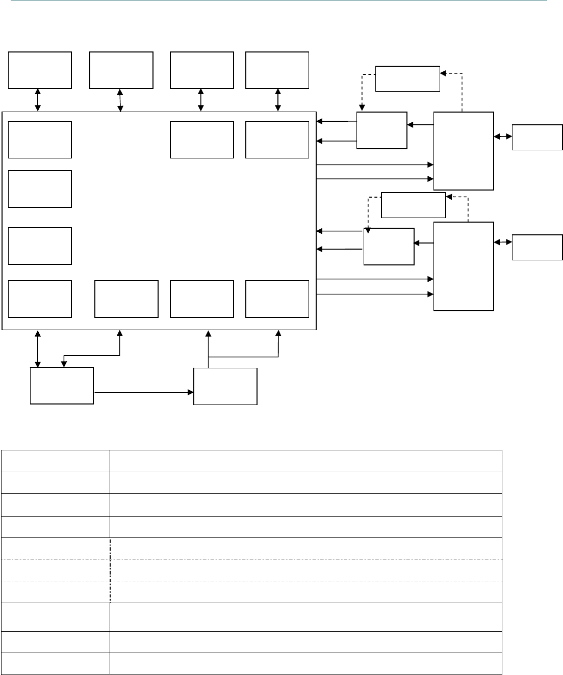
2.1.1 System Block Diagrams
2.1.2 Module Specification
CPU Atheros AR9342
RAM DDR2 SDRAM 512Mbits/64MByte
Flash 128Mbits/16MByte
Antenna 2T2R(2 x I-PEX connector)
Output/power
UART TXD.RXD.CTS.RTS 3.3VDC/0.5A, baud rate: 9600~115200bps
USB USB (device) 5VDC/0.5A
LED indicator 1. Power LED
2. WLAN LED
Button initial/reset button
Console port Reserved for debug
AR9342
MII/RMII
/RGMII
PCI Express
I2S/
SPDIF
USB
MAC/PHY
UART
H-Speed
Internal LDO
for GPIO
Internal SW-
REG 1.2V
UART
L-Speed
Internal
LDO for
Crystal
40 MHz
SPI Flash
128 Mbits
DDR2
512 Mbits
Debug
Console
LC type
diplexer
Wideband E
XT LAN
SP3T
RFSW IPEX0
IPEX1
Wafer
2x7 pin
External
SW-REG
Wideband E
XT LAN
LC type
diplexer
SP3T
RFSW
2GHz Rx0
5GHz Rx0
2GHz Tx0
5GHz Tx0
2GHz Rx1
5GHz Rx1
2GHz Tx1
5GHz Tx1
2.6V or 1.8V
EXT 5V or 3.3V supply
3.1V
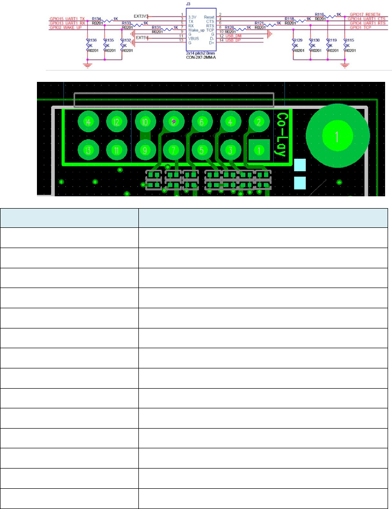
2.1.3 PCB Characteristics
Printed Circuit Board: FR4, UL94V-0, 6 Layers Dimension:
I/O placement: 14 pins wafer (definition as following)
pin definition
1 3.3V
2 Reset
3 TX
4 CTS
5 RX
6 RTS
7 Wake_up
8 TCP
9 GND
10 GND
11 5V
12 USB D-
13 GND
14 USB D+
2.1.4 Environmental Conditions
Preservation Temperature: -25 ~ 60 ˚C
Preservation Humidity: 10~90% non-condensing
Operation Temperature: 0 ~ 50˚C
Operation Humidity: 10~90% non-condensing
2.1.5 ESD
±8kV for Air Discharge
±4kV for Contact Discharge
2.2. Protocol:
Item Protocol
1 FTP client for firmware update
2 RAW TCP printing protocol (Port 9100 printing)
3 LPR Printing Protocol (Port 515 printing)
4 SNMP v1: Get
P
r
i
n
t
e
r
Status.
(
P
r
i
n
t
Name, Port Number,
P
r
i
n
t
e
r
S
t
a
t
u
s
…)
5 DHCP Client: Station mode
6 BOOTP
7 RARP
8 ARP
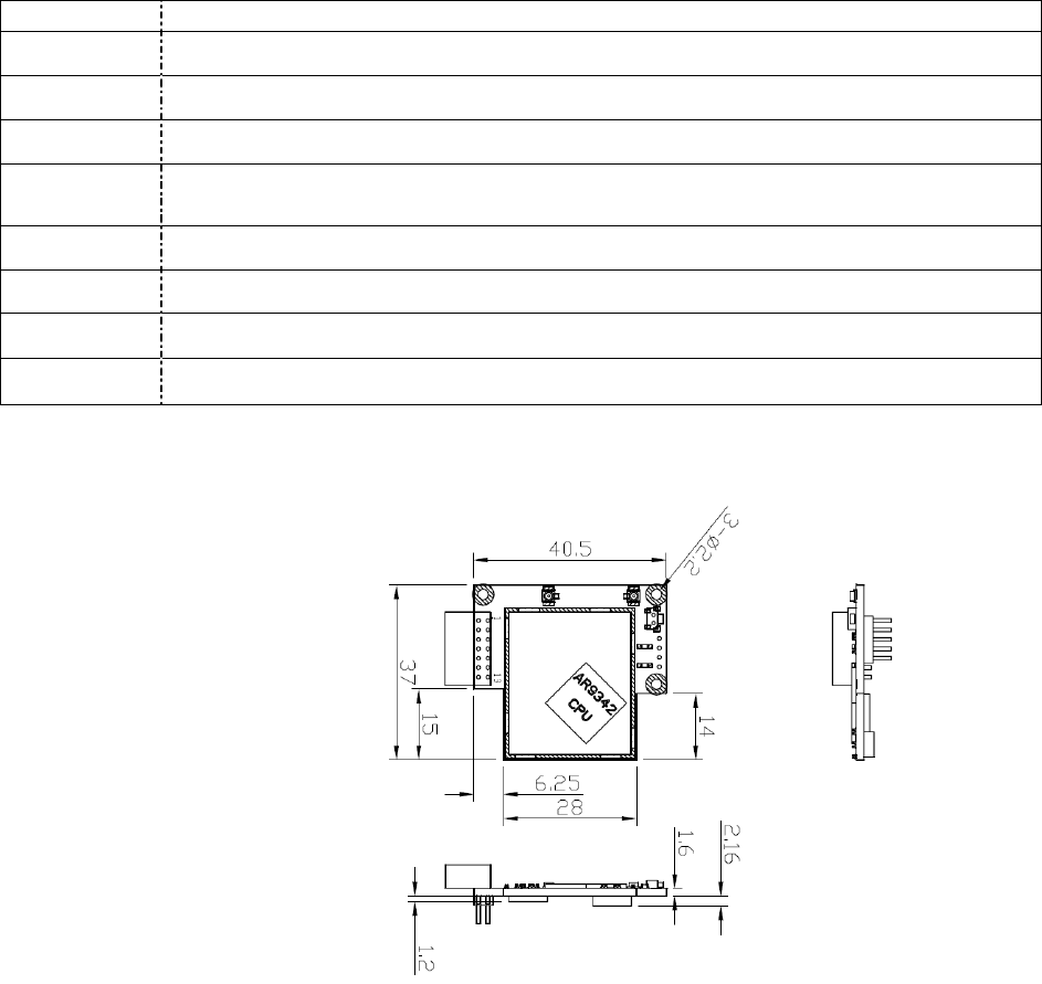
2.3. Mechanical Dimension:

3. AT command
Convention
For every AT command its response is a status, the default response should be an
ASCII character byte starting from ‘0’, ‘0’ indicate the request is done successfully , others
indicate independent status, but ‘1’ may indicate the request is not complete
in certain circumstances.
For every AT command its input is defined, the input option with underline indicate the
default value for the module.
Angle Brackets (“<” and “>”) indicate the value in the brackets is an arbitrary string.
Every listed AT command should be ended with two binary character 0x0D 0x0A.
AT Commands
3.1. Set UART baud Rate (wait for confirmation for both printer and module)
AT+UARTBAUD=n
n Baud rate
0 9600
1 14400
2 19200
3 38400
4 56000
5 57600
5 115200
5 230400
5 460800
5 921600
Return status
3.2. AT Command Response Type
AT+RESP=n
n=0: Single Byte Mode -AT response will be either “0”, “1”, or any single byte
n=1: String Mode -AT response will be either “OK” or “Fail”.
Return status
3.3. Time Setting (UTC)
AT+TIME=
YYYY.MM.DD-hh:mm:ss
Return status
3.4. Enable/Disable WLAN Interface
AT+WACTIVE=n
n=0: Disable
n=1: Enable
Return status
3.5. File Transfer
AT+WFILE=<file name>,<file size>,<file
content>
Return ‘0’
3.6. Reboot WLAN Module
AT+WREBOOT
Return ‘0’
3.7. Reset to Default
AT+WRESET
Return ‘0’
3.8. Set Host name
AT+WHOSTNAME=<hostname>
Return status
3.9. Wireless LAN Basic Setting
3.9.1. Set WLAN Mode
AT+WMODE=n
n=1: 11NAHT20 -802.11n A-Band (5GHz)
n=2: 11NGHT20 -802.11n G-Band (2.4Gz)
Return status
3.9.2. Set AP/client mode
AT+WAPMODE=n
n=0: client mode n1: AP mode
Return status
3.9.3. Enable/Disable DHCP Client
AT+WDHCPC=n
n=0: Disable
n=1: Enable
Return status
3.9.4. Static IP, Subnet Mask, Gateway Set
AT+WSTATIC=<Static
IP>,
<SubNet Mask>,Gateway>, <Domain
Name Server>
Return status
3.9.5. Set Client Mode SSID
AT+WSSID=<SSID>
Return status
3.9.6. Set AP Mode SSID
AT+WAPSSID=<SSID>
Return status
3.9.7. Set Wireless Roaming Option
AT+WROAM=<threshold>, <delta>
m=-30~-90(dBm): Threshold
n=0~30 (dB): Delta
Return status
3.10. Wireless LAN Security Setting
3.10.1. Set Security Mode
AT+WSECURITY=n
n=0: None
n=1: WEP
n=2: WPA/WPA2-PSK
n=3: WPA2-EAP
Return status
3.11. Wireless LAN WEP Setting
3.11.1. Set WEP Key Index
AT+WWEPINDEX=n
n=1~4
Return status
3.11.2. Set WEP Key
AT+WWEPKEYn=<key>
n=1~4
<key> is 10 or 26 hexadecimal digits (or empty to clear the current setting)
Return status
3.12. WPA2 Setting
3.12.1. Set WPA2-PSK Key
AT+WWPA2PSK=<key>
<key> is 8~63 ASCII characters or a 32-byte key formatted as an ASCII
hexadecimal number.
Return status
3.12.2. Set AP Mode WPA2-PSK Key
AT+WAPWPA2PSK=<key>
<key> is 8~63 ASCII characters or a 32-byte key formatted as an ASCII
hexadecimal number.
Return status
3.12.3. Set WPA2-EAP Identity
AT+WEAPIDENTITY=<name>,
<
password
>
Return status
3.12.4. Set WPA2-EAP Method
AT_WEAPMETHOD=n
n=0: EAP-TLS
n=1: PEAPv0 with EAP-MSCHAPv2
n=2: EAP-TTLS with EAP-MSCHAPv2
Return status
3.12.5. Set WPA2-EAP Certificate File (*.pem)
AT+WEAPCERT=<Type>, <Size>,
<Data>
Type: “0” -> CA Certificate File
“1” -> Client Certificate File
“2” -> Client Private Key File
Size is in unit byte
Return status
3.13. Firmware Update Mechanism
3.13.1. Module Firmware Upgrade
AT+MFIRMWARE=<file size>,<file
content>
Return status
*Return “Failed” if firmware checksum error, otherwise “OK”.
3.13.2. FTP Server Check Request
AT+MFTPCHECK=
<FTP
Server
IP (or
server
name)>, <ID>, <Password>,
<Directory>, <Printer_Version>
Return <1 byte of status>, <3 bytes of Co nfig size> <Config>, <3 bytes of Data
size> <Data>, <4 bytes of printer firmware size> <checksum><printer firmware>
*status:
0x00: Operation Success (FTP check finished, no need to upgrade firmware)
0x01: Upgrade Printer only
0x02: Upgrade Module only (Module Reboot Required)
0x03: Upgrade both Printer and Module (Module Reboot Required)
0x04: Connecting Refused
0x05: Connection Timeout (Retry 3 Times)
3.14. Status
3.14.1. Get WLAN State
AT+WSTATE=?
Return <Disabled/Not Connected/Connected>, <RSSI value string in dBm>,
<channel>, <speed>
Return 0 on any not applicable field.
3.14.2. Get MAC/IP Address
AT+WMAC=?
Return <MAC>, <IP>,<Subnet Mask>,<Gateway>
Return 0.0.0.0 when any not applicable IP.
3.14.3. Get Site Survey Result
AT+WSCAN=?
Return <SSID_1>, <BSSID_1>, <NetworkType_1>, <Channel_1>, <RSSI_1>,
<Security_1>; <SSID_2>, <BSSID_2>, <NetworkType_2>, <Channel_2>,
<RSSI_2>, <Security_2>; <SSID_3>….
3.14.4. Get Module SNMP Information
AT+WSNMPINFO=?
Return<ifNumber>, <ifIndex>, <ifDescr>, <ifType>, <ifMtu>, <ifSpeed>,
<ifPhysAddress>, <ifAdminStatus>, <ifOperStatus>, <ifLastChange>, <ifInOctet>,
<ifInUcastPkts>, <ifInNUcastPkts>, <ifInDiscards>, <ifInErrors>,
<ifInUnknownProtos>, <ifOutOctets>, <ifOutUcastPkts>, <ifOutNUcastPkts>,
<ifOutDiscards>, <ifOutErrors>, <ifOutQLen>, <ifSpecific>
3.14.5. Get Hostname
AT+WHOSTNAME=?
Return<hostname>

4. Network command
Format
To ensure all transfers over UART are operating as expectation, each transfer is required to
include the following fields:
● An Opcode which defines the specific operation, the operation may be different
between the Printer and the Module.
● A transfer size designates the whole size of this transfer. Target should drop this
transfer and acknowledge Initiator with error when received size is different to this
value.
* All the fields denoted in transfers are adhering to Network Byte Order (Big Endian).
Transfer Commands:
Printer Command Set:
Data Write Command:
This command provides function for Initiator to write data to Target.
Initiator Request:
Module Ready Signal:
Module Request:
*Version: String: [MAJOR NUMBER].[MINOR NUMBER].[BUILD NUMBER]
AT Command:
Printer can communicate AT command with Module in following format.
Initiator Request:
Target Response:
Opcode Transfer size Data Checksum
Value 0x1100 Size Data Reserved
Size (Byte) 2 3 <16M 2
Opcode Transfer size F/W Ver. Checksum
Value 0xFF00 Size Version* Reserved
Size (Byte) 2 3 8 2
Opcode Transfer size Data Checksum
Value 0x2000 Size AT command Reserved
Size (Byte) 2 3 <16M 2
Opcode Transfer size Data Checksum
Value 0x2000 Size AT Response Reserved
Size (Byte) 2 3 <16M 2

NT Command:
Printer can establish connection through NT command in following format.
Initiator Request:
Target Response:
Network Command Set:
Printer can establish connection through commands below.
Network Open Command: (Printer Only) NT+SOCKETOPEN=<Type>,<IP>,<Port>
<Type>: “0” -> TCP Socket Connect
“1” -> TCP Socket Accept “2” -> UDP Socket Open
Return <SocketID>
Socket SetOpt Command:
NT+SETSOCKETOP=<SocketID>,<option>,<optval>
<SocketID> is the socket ID derived from connection establish command.
<option>: “1”-> TCP_MAXSEG
“2”-> SO_RCVTIMEO
“3”-> SO_RCVBUF
Return 0x00 on success, 0xFF on failure
Socket Transfer Command:
NT+SENDDATA =<Type>,<SocketID>,<Data>
<Type>: “0” -> TCP Send Data
“1” -> UDP Send Data
<SocketID> is the socket ID derived from connection establish command.
Return number of bytes transferred on success, 0xFF on failure
Network Close Command: (Printer Only)
NT+SOCKETCLOSE=<SocketID>
<SocketID> is the socket ID of the connection which you want to close. Return 0x00 on
success, 0xFF on failure
Supporting Security:
1. WPA-Personal (TKIP), Enterprise
2. WPA2-Personal (AES Hardware), Enterprise
3. Wired equivalent privacy protocol(WEP)
4. Vendor EAP Type(s): EAP-TTLS/MSCHAPv2, PEAPv0/MSCHAPv2, EAP-FAST/
MSCHAPv2, EAP-TLS
Opcode Transfer size Data Checksum
Value 0x3000 Size NT command Reserved
Size (Byte) 2 3 <16M 2
Opcode Transfer size Data Checksum
Value 0x3000 Size NT response Reserved
Size (Byte) 2 3 <16M 2

Revise History
Date Content Editor


Corporate Headquarters Li Ze Plant
9F., No.95, Minquan Rd., Xindian Dist., No.35, Sec. 2, Ligong 1st Rd., Wujie Township,
New Taipei City 23141, Taiwan (R.O.C.) Yilan County 26841, Taiwan (R.O.C.)
TEL: +886-2-2218-6789 TEL: +886-3-990-6677
FAX: +886-2-2218-5678 FAX: +886-3-990-5577
Web site: www.tscprinters.com
TSC Auto ID Technology Co., Ltd.