TSC Auto ID Technology RFWRN WiFi abgn module User Manual Alpha 4L user manual Page5
TSC Auto ID Technology Co., Ltd. WiFi abgn module Alpha 4L user manual Page5
Contents
User Manual_V1

Al
B
a
pha-
4
a
rcod
e
4
L Se
e
Pri
n
r
ies
n
ter
US
E
MAN
U
E
R’S
U
AL

Copyright Information
©2013 TSC Auto ID Technology Co., Ltd.
The copyright in this manual, the software and firmware in the printer described
therein are owned by TSC Auto ID Technology Co., Ltd, All rights reserved.
CG Triumvirate is a trademark of Agfa Corporation. CG Triumvirate Bold
Condensed font is under license from the Monotype Corporation. Windows is a
registered trademark of Microsoft Corporation.
All other trademarks are the property of their respective owners.
Information in this document is subject to change without notice and does not
represent a commitment on the part of TSC Auto ID Technology Co. No part of
this manual may be reproduced or transmitted in any form or by any means, for
any purpose other than the purchaser’s personal use, without the expressed
written permission of TSC Auto ID Technology Co.
Agenc
Wichtig
e
1. Bitte l
e
2. Hebe
n
3. Vor j
e
A
ero
s
4. Die N
e
5. Das
G
6. Bei d
e
Besc
h
7. Beac
h
8. Diese
y Compli
a
C
E
E
N
E
N
5,
I
E
N
E
N
FC
C
FC
C
FC
C
FC
C
IC
E
IC
R
IC
R
IE
C
E
G
G
G
e
Sicherhei
t
e
sen Sie di
e
n
Sie diese
A
e
dem Reinig
e
s
olreiniger.
A
etzanschluß
G
erät ist vor
F
e
r Aufstellun
g
h
ädigungen
h
h
ten Sie bei
m
s Gerät kan
n
a
nce and
A
E
CLASS B
N
55022:20
1
N
55024:20
1
I
EC61000-
4
N
301489-1,
E
N
50556:201
C
CFR Title
C
CFR Title
C
CFR Title
C
47 CFR P
a
E
S-003 Issu
e
R
SS-102 Is
s
R
SS-247 Is
s
C
62209-2(2
0
N 60950-
1
G
B 9254
G
B 4943.1
G
B 17625.
1
t
s-Hinweis
e
e
se Hinweis
s
A
nleitung fr
e
n ist das G
e
A
m besten ei
g
-Steckdose
s
F
euchtigkeit
g
des Gerät
e
h
ervorrufen.
m
Anschluß
a
n
bis zu ein
e
A
pproval
s
1
0/AC:201
1
1
0 ,IEC610
0
4
-6, IEC61
0
E
N301489-
1
3,EN62311
47 Part 15
S
47 Part 15
S
47 Part 15
S
a
rt 2(2.109
3
e
5 Class B
s
ue 5
s
ue 1
0
10),IEEE 1
5
1
1
e
s
orgfältig du
r
den später
e
e
rät vom Str
o
g
net sich ei
n
s
oll nahe de
m
zu schtze
n
e
s ist auf sic
h
a
ns Stromn
e
r Außentem
p
- ii -
s
1
, EN6100
0
0
0-4-2,IEC
6
0
00-4-8, IE
C
1
7,EN3003
:2008, EN
6
S
ubpart B
C
S
ubpart C
S
ubpart E
3
) ,ANS/IEE
E
5
28-2013
r
ch.
e
n Gebrauch
o
mentz zu tr
e
n
angefeucht
e
m
Gerät an
g
n
.
h
eren Stand
e
tz die Ansc
h
p
eratur von
m
0
-3-2:2014,
E
6
1000-4-3,
C
61000-4-1
28,EN301
8
6
2209-2:20
C
lass B
E
C95.1-199
2
auf.
e
nnen. Ver
w
e
tes Tuch z
u
g
ebracht und
zu achten.
E
h
lußwerte.
m
aximal 40
ɗ
E
N61000-3
-
IEC61000-
4
1
8
93,
10, EN624
7
2
, IEEE 152
8
w
enden Sie
k
u
r Reinigung
leicht zugä
n
E
in Kippen o
ɗ
betrieben
w
-3:2013
4
-4, IEC61
0
7
9:2010
8
-2003
k
eine Flüssig
.
n
glich sein.
o
der Fallen k
ö
w
erden.
0
00-4-
-oder
ö
nnte

- iii -
Battery safety warning:
DO NOT throw the battery in fire.
DO NOT short circuit the contacts.
DO NOT disassemble the battery.
DO NOT throw the battery in municipal waste.
The symbol of the crossed out wheeled bin indicates that the battery should not be placed in municipal
waste.
CAUTION
Risk of explosion if battery is replaced by an incorrect type.
Dispose of used batteries according to the instructions.
Class B:
FEDERAL COMMUNICATIONS COMMISSION INTERFERENCE STATEMENT
This equipment has been tested and found to comply with the limits for a Class B digital
device, pursuant to part 15 of the FCC Rules. These limits are designed to provide
reasonable protection against harmful interference in a residential installation. This
equipment generates, uses and can radiate radio frequency energy and, if not installed and
used in accordance with the instructions, may cause harmful interference to radio
communications. However, there is no guarantee that interference will not occur in a
particular installation. If this equipment does cause harmful interference to radio or television
reception, which can be determined by turning the equipment off and on, the user is
encouraged to try to correct the interference by one or more of the following measures:
-Reorient or relocate the receiving antenna.
-Increase the separation between the equipment and receiver.
-Connect the equipment into an outlet on a circuit different from that to which the receiver is connected.
-Consult the dealer or an experienced radio/ TV technician for help.
This device complies with Part 15 of the FCC Rules. Operation is subject to the following two
conditions: (1) This device may cause harmful interference, and (2) this device must accept any
interference received, including interference that may cause undesired operation.
CAUTION:
Any changes or modifications not expressly approved by the grantee of this device could void the
user's authority to operate the equipment.

- iv -
This device complies with Part 15 of the FCC Rules. Operation is subject to the following two
conditions: (1) This device may not cause harmful interference, and (2) this device must accept any
interference received, including interference that may cause undesired operation.
IMPORTANT NOTE:
Federal Communication Commission (FCC) Radiation Exposure Statement
This EUT is compliance with SAR for general population/uncontrolled exposure limits in ANSI/IEEE
C95.1-1999 and had been tested in accordance with the measurement methods and procedures
specified in OET Bulletin 65 Supplement C. This equipment should be installed and operated contact
with the radiator & your body.
For body worn operation, this device has been tested and meets the FCC RF exposure guidelines
when used with the belt clip accessory provided by TSC. Use of other accessories may not ensure
compliance with FCC RF exposure guidelines.
This device complies with Industry Canada's licence-exempt RSSs. Operation is subject to the
following two conditions:
(1) This device may not cause interference; and
(2) This device must accept any interference, including interference that may cause undesired
operation of the device.
Le présent appareil est conforme aux CNR d'Industrie Canada applicables aux appareils radio
exempts de licence. L'exploitation est autorisée aux deux conditions suivantes : (1) l'appareil ne doit
pas produire de brouillage, et (2) l'utilisateur de l'appareil doit accepter tout brouillage radioélectrique
subi, même si le brouillage est susceptible d'en compromettre le fonctionnement.
High Power Radars: High power radars are allocated as primary users (meaning they have priority) in
the 5250MHz to 5350MHz and 5650MHz to 5850MHz bands. These radars could cause interference
and/or damage to Wireless LAN devices used in Canada.
Les utilisateurs de radars de haute puissance sont désignés utilisateurs principaux (c.-à-d., qu'ils ont
la priorité) pour les bandes 5250 - 5350 MHz et 5650 - 5850 MHz. Ces radars pourraient causer du
brouillage et/ou des dommages aux dispositifs LAN-EL.
IC Radiation Exposure Statement
This EUT is compliance with SAR for general population/uncontrolled exposure limits in IC RSS-102
and had been tested in accordance with the measurement methods and procedures specified in IEEE
1528.

- v -
RF exposure warning (WiFi)
This equipment must be installed and operated in accordance with provided instructions and must not
be co-located or operating in conjunction with any other antenna or transmitter. End-users and
installers must be providing with antenna installation instructions and transmitter operating conditions
for satisfying RF exposure compliance.
This device meets the government's requirements for exposure to radio waves. This device is
designed and manufactured not to exceed the emission limits for exposure to radio frequency (RF)
energy set by the Federal Communications Commission of the U.S. Government.
The exposure standard employs a unit of measurement known as the Specific Absorption Rate, or
SAR. The SAR limit set by the FCC is 1.6 W/kg. Tests for SAR are conducted using standard
operating positions accepted by the FCC with the EUT transmitting at the specified power level in
different channels.
Canada, Industry Canada (IC) Notices
This Class B digital apparatus complies with Canadian ICES-003 and RSS-247.
Operation is subject to the following two conditions: (1) this device may not cause
interference, and (2) this device must accept any interference, including interference that
may cause undesired operation of the device.
Radio Frequency (RF) Exposure Information
The radiated output power of the Wireless Device is below the Industry Canada (IC)
radio frequency exposure limits. The Wireless Device should be used in such a manner
such that the potential for human contact during normal operation is minimized.
This device has been evaluated for and shown compliant with the IC Specific Absorption
Rate (“SAR”) limits when installed in specific host products operated in portable
exposure conditions. (For WiFi)
Canada, avis d'Industry Canada (IC)
Cet appareil numérique de classe B est conforme aux normes canadiennes ICES-003 et
RSS-247.
Son fonctionnement est soumis aux deux conditions suivantes : (1) cet appareil ne doit
pas causer d'interférence et (2) cet appareil doit accepter toute interférence, notamment
les interférences qui peuvent affecter son fonctionnement.

- vi -
Informations concernant l'exposition aux fréquences radio (RF)
La puissance de sortie émise par l’appareil de sans fil Dell est inférieure à la
limite(1.6W/Kg) d'exposition aux fréquences radio d'Industry Canada (IC). Utilisez
l’appareil de sans fil Dell de façon à minimiser les contacts humains lors du
fonctionnement normal.
Ce dispositif a été évalué pour et démontré conforme à la Taux IC d'absorption
spécifique ("SAR") des limites(1.6W/Kg) lorsqu'il est utilisé dans des conditions
d'exposition portatifs. (For WiFi)
⭥⊐ᆹޘ䆖˖
Ƽ यሶ⭥⊐ᢄҾ⚛ѝDŽ
Ƽ यሶ⭥⊐᧕⛩⸝䐟DŽ
Ƽ нਟ䀓⭥⊐DŽ
Ƽ нҡሶ⭥⊐ᖃᡀа㡜ᓏᔳ⢙༴⨶DŽ
Ƽ ᢃ৹Ⲵඳ൮Ầㅖਧ㺘⽪⭥⊐нᓄ䈕㻛᭮㖞ࡠа㡜ᓏᔳึѝDŽ
⌘
:
Ƽ ᴤᦒн↓⺞රਧ㊫රⲴ⭥⊐, ሶӗ⭏⠶⛨ড䲙DŽ
Ƽ 䈧ṩᦞ֯⭘䈤᰾༴⨶⭘䗷Ⲵ⭥⊐DŽ

- vii -
Contents
1. Introduction ................................................................................................................ 1
1.1 Product Introduction ............................................................................................. 1
1.2 Product Features ................................................................................................... 2
1.2.1 Printer Standard Features ..............................................................................................2
1.2.2 Printer Optional Features ............................................................................................... 3
1.3 General Specifications .......................................................................................... 5
1.4 Print Specifications ............................................................................................... 5
1.5 Media Specifications ............................................................................................. 6
2. Operations Overview .................................................................................................. 7
2.1 Unpacking and Inspection .................................................................................... 7
2.2 Printer Overview .................................................................................................. 8
2.2.1 Front View .......................................................................................................................... 8
2.2.2 Rear View ........................................................................................................................... 9
2.3 Operator Control ................................................................................................ 10
2.3.1 LED Indication and Keys .............................................................................................. 10
2.3.2 LED Indication and Keys for LCD (Option) ............................................................. 11
3. Setup .......................................................................................................................... 12
3.1 Install the Belt Clip and Battery .......................................................................... 12
3.2 Charge the Battery ............................................................................................... 13
3.2.1 Charge the Battery .......................................................................................................... 13
3.3 Loading the Media ............................................................................................... 14
3.3.1 Loading the Media .......................................................................................................... 14
3.3.2 Loading Media in Peel-off Mode ................................................................................. 16
3.3.3 Loading the Fan-fold/External Media ....................................................................... 19
3.3.4 Loading the Linerless Media (Option) ...................................................................... 21
3.4 Connecting the Printer ...................................................................................... 22
3.4.1 Cable Communications ................................................................................................ 22
3.4.2 Wireless Communications with Wi-Fi (Option) ................................................... 22
3.5 Install the IP54-rated Environmental Case with Shoulder Strap (Option) ...... 23
3.6 Install the Adapter for 0.75” and 1” Paper Core (Option) ................................. 24
3.7 Install the Belt Strap (Option/ Standard for linerless model) ........................... 26

- viii -
4. Power-on Utilities .................................................................................................... 28
4.1 Power-on Utility for Standard Panel .................................................................. 28
4.1.1 Media Sensor Calibration ............................................................................................ 29
4.1.2 Self-test and Dump Mode............................................................................................. 29
4.1.3 Printer Initialization ..................................................................................................... 30
4.2 Power-on Utility for LCD Panel (Option) ........................................................... 31
4.2.1 Media Sensor Calibration ............................................................................................. 31
4.2.2 Self-test and Dump Mode ............................................................................................ 32
4.2.3 Printer Initialization .................................................................................................... 33
4.3 Self-test ............................................................................................................... 34
4.4 Dump mode ........................................................................................................ 35
4.5 Printer defaults ................................................................................................... 36
5. Diagnostic Tool ......................................................................................................... 37
5.1 Start the Diagnostic Tool .................................................................................... 37
5.2 Printer Function ................................................................................................. 38
5.3 Setting Wi-Fi by Diagnostic Tool (Option) ........................................................ 39
6. LCD Menu Function (Option) .................................................................................. 40
6.1 How to use the LCD to set the printer ................................................................ 40
6.2 Main Menu Overview ......................................................................................... 43
6.3 Setup ................................................................................................................... 44
6.3.1 Printer Setup ................................................................................................................... 44
6.3.1-1 Printer setup for TSPL2 ............................................................................................ 44
6.3.1-2 Printer setup for ZPL2 .............................................................................................. 46
6.3.2 Sensor ............................................................................................................................... 48
6.3.3 Serial Comm. .................................................................................................................. 49
6.3.4 Wireless LAN .................................................................................................................. 50
6.3.5 Date Time .......................................................................................................................... 51
6.3.6 Display ............................................................................................................................... 52
6.4 File Manager ...................................................................................................... 53
6.5 Diagnostics ......................................................................................................... 54
6.5.1 Print Config. .................................................................................................................... 54
6.5.2 Dump Mode ...................................................................................................................... 54
6.5.3 Battery ............................................................................................................................... 55
6.5.4 Print Head ........................................................................................................................ 55

- ix -
6.6 Language ............................................................................................................ 56
6.7 Service ................................................................................................................. 56
7. Troubleshooting ....................................................................................................... 57
8. Maintenance ............................................................................................................. 59
Revise History ............................................................................................................... 60

1. Introduction
1.1 Product Introduction
Thank you very much for purchasing TSC bar code printer.
Enjoy TSC’s reputation for cost-efficient, high durability printers with the Alpha-4L
economical receipt printer. The Alpha-4L is a comfortable, light-weight printer capable of
working with any mobile receipt printing application where you need quick, simple receipts
on demand. Our Alpha-4L is designed for a rough life, inside the IP54-rated environmental
case to resist dust and water and with its rubber over-mold design prepared to take up to a
five foot fall and keep printing. These small and light printers can be worn comfortably for a
full shift, without interfering with the user’s tasks. Use USB, optional Wireless or serial to
connect to a mobile computer or even a smart phone and produce clear easy-to-read
receipts hour after hour.
This document provides an easy reference for operating the Alpha-4L.
To print label formats, please refer to the instructions provided with your labeling software;
if you need to write the custom programs, please refer to the TSPL/TSPL2 programming
manual that can be found on the accessories CD-ROM or on TSC website at
http://www.tscprinters.com.
о Applications
Portable point of sale
Retail item marking, markdowns, shelf labeling & shelf talkers
Labels for shipping & receiving
Inventory control
Cross-docking
Pick, pack & apply operations
Print pick tickets
Logistics receipts
- 2 -
1.2 Product Features
1.2.1 Printer Standard Features
The printer offers the following standard features.
Product standard feature
Direct thermal printing
Black mark reflective sensor
(center position , black mark in back side)
Gap transmissive sensor (Fixed, center of offset 2.75 mm to right from center)
Head open sensor
Peeler sensor
2 operation buttons (On/off and feed)
3 LEDs for printer status, 3 LEDs for battery status
USB 2.0 (full speed) interface
32 MB SDRAM memory
16 MB FLASH memory
Micro SD card reader for memory expansion up to SDHC 4G (max.)
DC 7.2V/5800 mAh Li-ion rechargeable battery
Real time clock
Powerful 32 bit 200 MHz RISC processor
Eltron
®
EPL and Zebra
®
ZPL emulation languages support
Internal 8 alpha-numeric bitmap fonts
Internal Monotype Imaging
®
true type font engine with one CG Triumvirate Bold
Condensed scalable font
Fonts and bar codes can be printed in any one of the four directions (0, 90,180,
270 degree)
Downloadable fonts from PC to printer memory
Downloadable firmware upgrades
Bar code, graphics/image printing
Supported bar code Supported image
1D bar code 2D bar code BITMAP, BMP, PCX
(Max. 256 colors
graphics)
Code128 subsets A.B.C,
Code128UCC, EAN128, Interleave 2
of 5, Code 39, Code 93, EAN-13,
EAN-8, Codabar, POSTNET, UPC-A,
UPC-E, EAN and UPC 2(5) digits,
MSI, PLESSEY, China Post, ITF14,
EAN14, Code 11, TELPEN,
PLANET, Code 49, Deutsche Post
Identcode, Deutsche Post Leitcode,
LOGMARS
CODABLOCK F
mode, DataMatrix,
Maxicode, PDF-417,
Aztec,
MicroPDF417, QR
code, RSS Barcode
(GS1 Databar)

- 3 -
Code page
Codepage 437 (English - US)
Codepage 737 (Greek)
Codepage 850 (Latin-1)
Codepage 852 (Latin-2)
Codepage 855 (Cyrillic)
Codepage 857 (Turkish)
Codepage 860 (Portuguese)
Codepage 861 (Icelandic)
Codepage 862 (Hebrew)
Codepage 863 (French Canadian)
Codepage 864 (Arabic)
Codepage 865 (Nordic)
Codepage 866 (Russian)
Codepage 869 (Greek 2)
Codepage 950 (Traditional Chinese)
Codepage 936 (Simplified Chinese)
Codepage 932 (Japanese)
Codepage 949 (Korean)
Codepage 1250 (Latin-2)
Codepage 1251 (Cyrillic)
Codepage 1252 (Latin-1)
Codepage 1253 (Greek)
Codepage 1254 (Turkish)
Codepage 1255 (Hebrew)
Codepage 1256 (Arabic)
Codepage 1257 (Baltic)
Codepage 1258 (Vietnam)
ISO-8859-1: Latin-1 (Western European)
ISO-8859-2: Latin-2 (Central European)
ISO-8859-3: Latin-3 (South European)
ISO-8859-4: Latin-4 (North European)
ISO-8859-5: Cyrillic
ISO-8859-6: Arabic
ISO-8859-7: Greek
ISO-8859-8: Hebrew
ISO-8859-9: Turkish
ISO-8859-10: Nordic
ISO-8859-15: Latin-9
UTF-8
1.2.2 Printer Optional Features
The printer offers the following optional features.
Product option feature User
option
Factory
option
2” LCD (Liquid crystal display), 128 x 64 pixels resolution
w/white LED backlight (with 4 buttons and 2 LEDs) ˕
WiFi module ˕
Zebra® CPCL emulation language support ˕
Media sensor position
(position selectable – right/left/center position-factory
adjustment, default – center position) ˕
Linerless kit ˕

- 4 -
Mini USB cable ˕
Mini USB to RS-232 (serial) converter cable ˕
IP54-rated environmental case with shoulder strap (for
standard model) ˕
IP54-rated environmental case (for standard model) ˕
IP54-rated environmental case with shoulder strap (for
linerless model) ˕
IP54-rated environmental case (for linerless model) ˕
Shoulder strap ˕
Vehicle power adaptor ˕
DC 7.2V/5800 mAh Li-ion rechargeable battery ˕
Charger station 1 cell ˕
Charger station 4 cell ˕
Belt strap ( standard for linerless model) ˕
Adapter for 0.75” & 1” paper core ( standard for linerless
model) ˕
- 5 -
1.3 General Specifications
General Specifications
Physical
dimensions 160 mm (W) x 191.6 mm (H) x 79 mm (D)
Mechanism Plastic with rubber over molded
Weight 0.945 kg (w/o battery)
Power
External power adapter
Input: AC 100-240V
Output: DC 12V 1A
Environmental
condition
Operation: -10 ~ 50˚C (14 ~ 122˚F)
Storage: -40 ~ 60 ˚C (-40 ~ 140˚F)
Relative humidity: 10 ~ 90% non-condensing
IP54 w/ IP54-rated environmental case
Drop 1.5m (5ft)
Drop 1.8m (6.5ft) w/ IP54-rated environmental case
Battery Spec
Charging time: 5~6 hr
Standby mode (Wi-Fi): up to 40 hr
Printing: one label per 2 minutes,
Condition Endurance (hr) 4”x6” Labels
Density 3 26 780
Density 8 21 650
Charging
capability
Internal charging capability (battery-in)
Auto-switching AC adapter
12-24VDC automobile cigarette lighter plug
External charging capability (battery-out)
1 battery charger station
4 battery charger station
1.4 Print Specifications
Print Specifications
Print head resolution
(dots per inch/mm) 203 dots/inch (8 dots/mm)
Printing method Direct thermal
Dot size
(width x length)
0.125 x 0.125 mm
(1 mm = 8 dots)
Print speed
(inches per second)
Max. 4 ips (100 mm/sec)
2,3 ips for peeler mode
Max. print width 4.09” (104 mm)
Max. print length 90” (2286 mm)
Printout bias Vertical: 1 mm max.
Horizontal: 1 mm max.

- 6 -
1.5 Media Specifications
Media Specifications
Media roll capacity Max. 2.65” (67.3 mm) OD
Media core diameter 12.7 mm ~ 25.4 mm (0.5” ~ 1”) ID core
Media type Continuous, die-cut, black mark, External fan-
fold, receipt, Linerless label (w/ linerless kit)
Media wound type Outside wound
Media width 50.8 mm ~ 112 mm
Media thickness 0.055 mm ~ 0.165 mm
Label length 12.7 mm ~ 2286 mm
Label length (peeler mode) 25.4 ~ 152.4 mm (1” ~ 6”)
External fan-fold media Stack height: 70 mm (2.75”)
Page length: 152 mm ~ 305 mm (6” ~ 12”)
Black mark Min. 8 mm (W) x 2 mm (H)
Gap height Min. 2 mm
- 7 -
2. Operations Overview
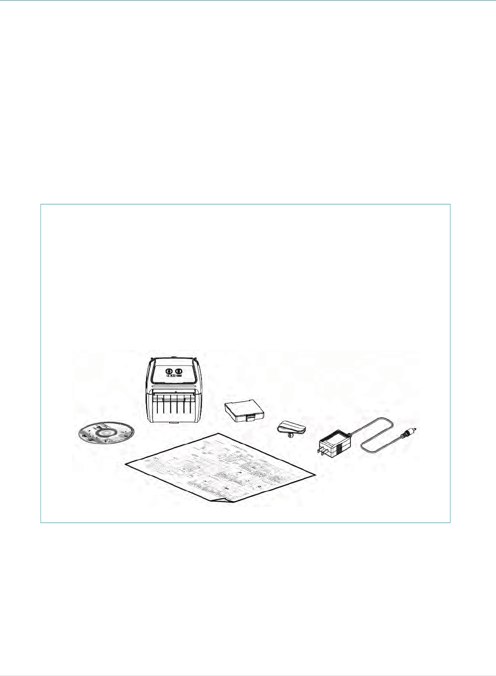
2.1 Unpacking and Inspection
This printer has been specially packaged to withstand damage during shipping. Please
carefully inspect the packaging and printer upon receiving the bar code printer. Please
retain the packaging materials in case you need to reship the printer.
Unpacking the printer, the following items are included in the carton.
If any parts are missing, please contact the Customer Service Department of your
purchased reseller or distributor.
One printer unit
One Li-ion rechargeable battery (5800 mAh)
One Windows labeling software/Windows driver CD disk
One quick installation guide
One auto-switching AC adaptor
One belt clip
- 8 -
2.2 Printer Overview
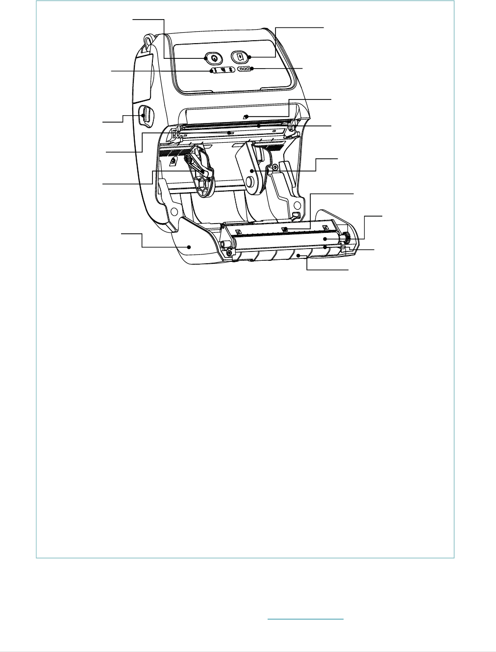
2.2.1 Front View
Note:
* The media sensor position is selectable by factory adjustment. Please refer to this figure
for default settings. (Default – center position)
* For LCD control panel (option), please refer to subsection 2.3.2 for more details.
1. Power on/off button
2. Feed button
3. Printer status LED indicator
4. Battery status LED indicator
5. Media cover release button
6. Peel-off sensor (Without for linerless model)
7. Print head
8. Transmissive sensor – Gap sensor
9. Media holder lock switch
10. Media holder
11. Media cover
12. Reflective sensor – Black mark sensor
13. Platen roller
14. Tear/Peeler bar (Without for linerless model)
15. Peeler module
9
2
1
34
6
8
7
5
10
11
12
13
15
14
- 9 -
2.2.2 Rear View
Note:
* Recommended MicroSD card specification.
SD card spec SD card capacity Approved SD card manufacturer
V1.0, V1.1 MicroSD 128 MB Transcend, Panasonic
V1.0, V1.1 MicroSD 256 MB Transcend, Panasonic
V1.0, V1.1 MicroSD 512 MB Transcend, Panasonic
V1.0, V1.1 MicroSD 1 GB Transcend, Panasonic
V2.0 SDHC CLASS 6 MicroSD 4 GB Transcend
- The DOS FAT file system is supported for the SD card.ġ
- Folders/files stored in the SD card should be in the 8.3 filename formatġ
1. Li-ion battery
2. Belt chip
3. Battery open clasp
4. Hanger for shoulder strap
5. External label entrance chute
6. USB interface
7. * MicroSD card socket
8. Power jack
1
3
2
4
7
6
5
8
- 10 -
2.3 Operator Control
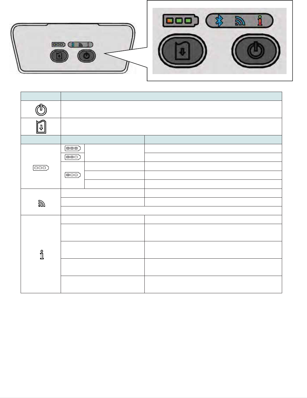
2.3.1 LED Indication and Keys
Keys Function
о Press and hold for 2-3 seconds to turn on the printer
о Press and hold for 2-3 seconds to turn off the printer
о Ready status: Feed one label
о Printing status: Pause the print job
LEDs Status Indication
Green (solid) Full charged
2/3 charged level
Green (solid) 1/3 charged level
Green (blinking) Low battery
Amber (solid) Battery is charging
Blue (solid) WiFi device is ready
Blue (blinking) WiFi device is communicating
Note: WiFi device is optional.
Off Printer is ready
Green (blinking) о Printer is paused
о Printer is downloading data
Red (solid) о Media cover is open
о Out of memory
Red (blinking) о No paper
о Paper jam
Amber (solid) о Clean data
о Printer is busy
- 11 -
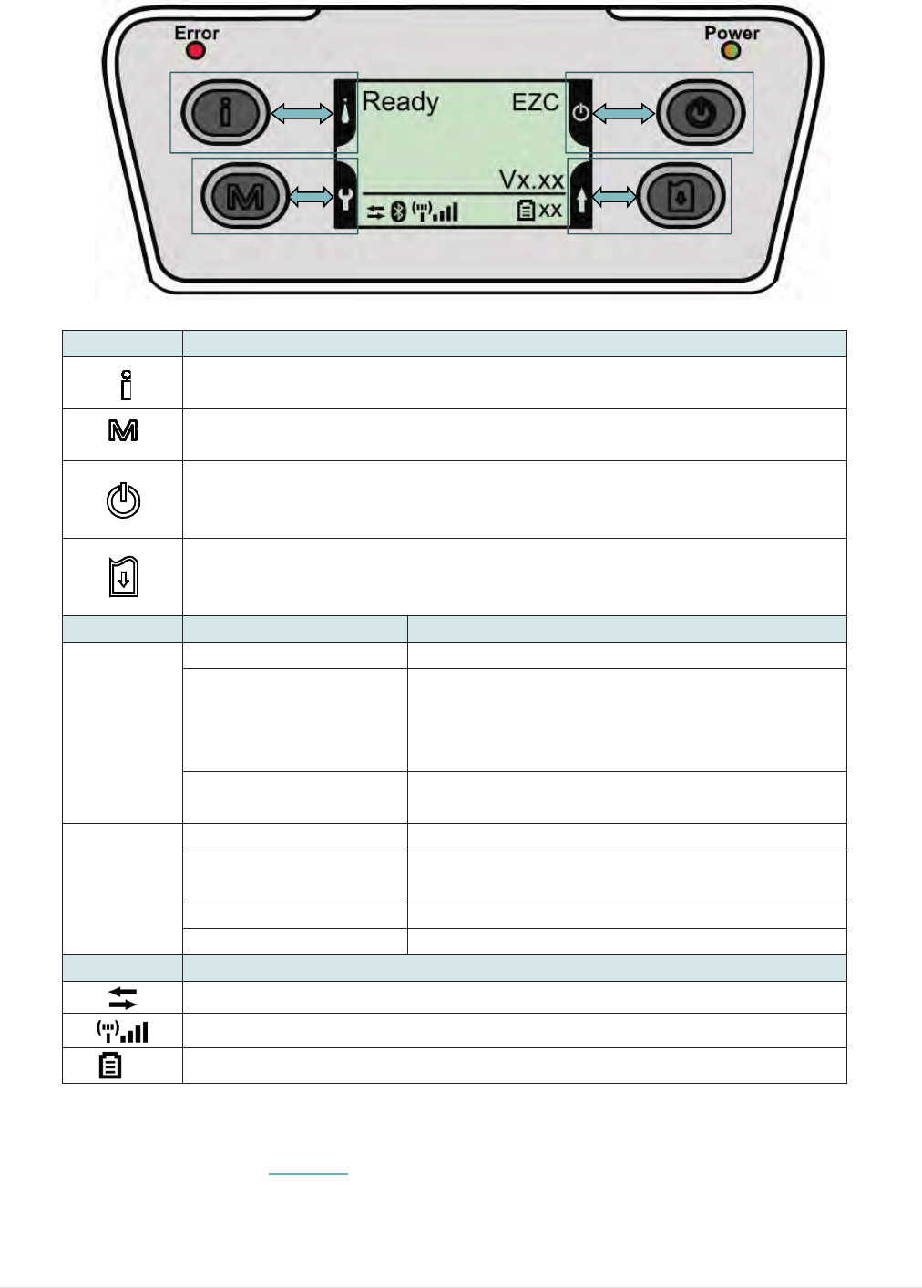
2.3.2 LED Indication and Keys for LCD (Option)
Note: Please refer to the section 6 for more details about LCD.
Keys Function
о Display the printer information
о Button for LCD setting menu
о Enter the printer setting menu
о Button for LCD setting menu
о Press and hold for 2-3 seconds to turn on the printer
о Press and hold for 2-3 seconds to turn off the printer
о Button for LCD setting menu
о Ready status: Feed one label
о Printing status: Pause the print job
о Button for LCD setting menu
LEDs Status Indication
Error
Off Printer is ready
Red (solid)
о Media cover is open
о Out of memory
о Clean data
о Printer is busy
Red (blinking) о No paper
о Paper jam
Power
Off Printer power is turned off
Green (solid) о Printer power is turned on
о Battery is full charged
Green (blinking) Low battery
Amber (solid) Battery is charging
LCD Indication
Printer has been connected with cable
Wi-Fi device has been connected
XX Battery capacity %
3
3
3
. Setu
p
3
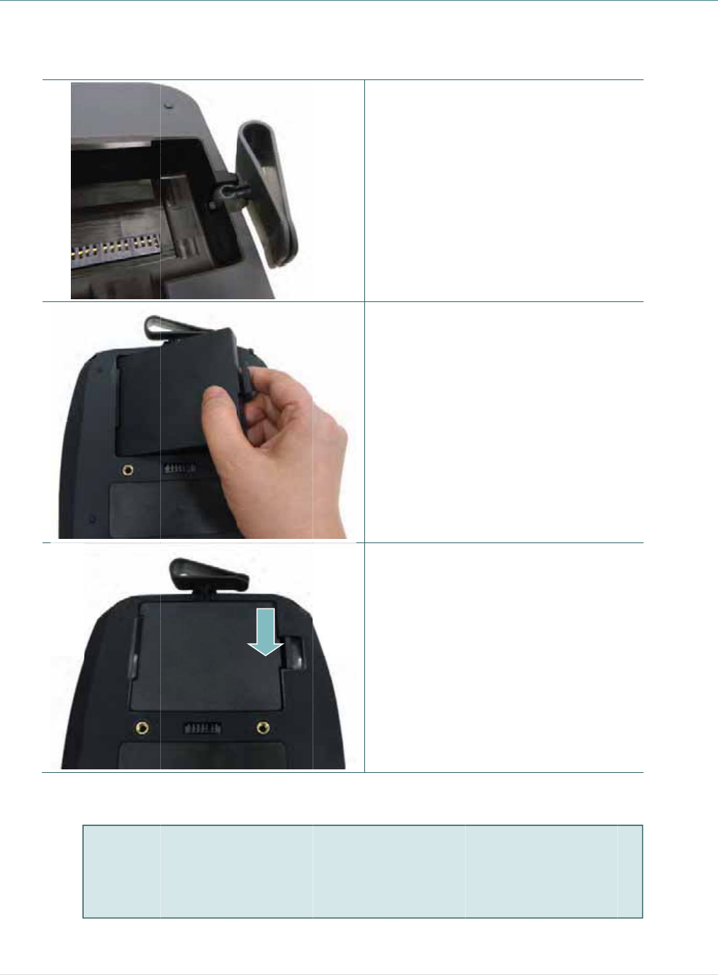
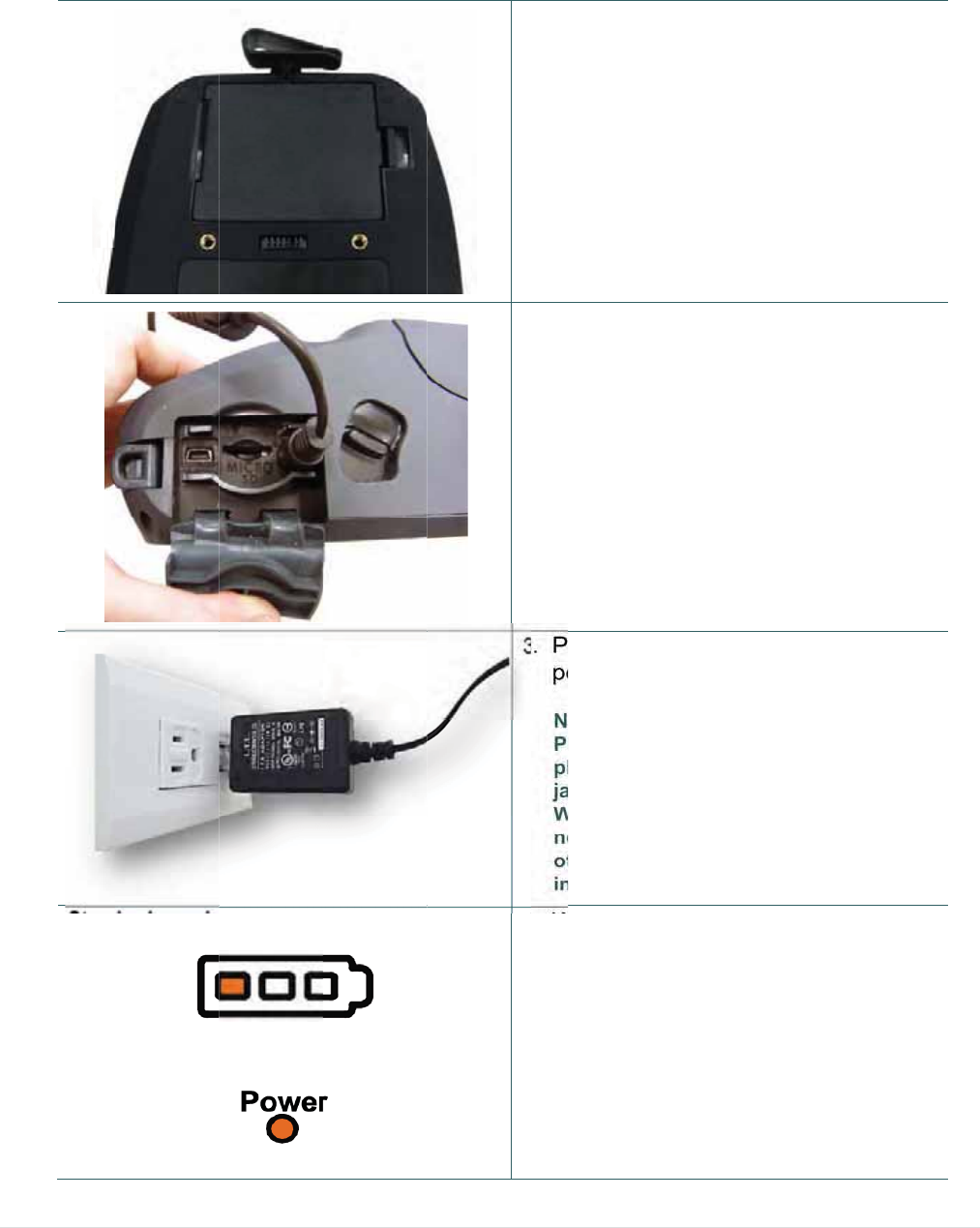
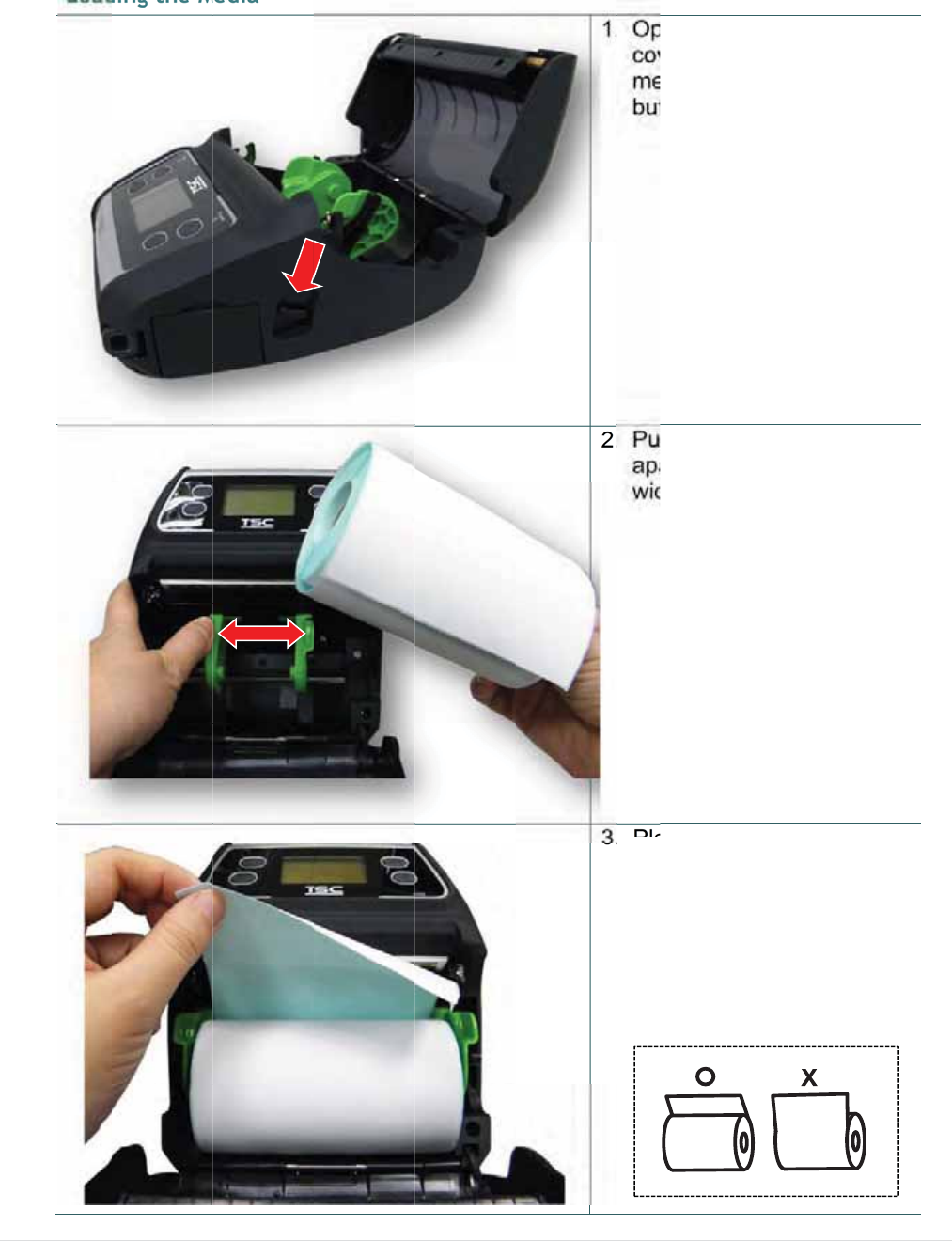
.1 Insta
p
ll the Be
Battery sa
f
DO NOT t
h
DO NOT d
The symb
o
placed in
m
lt Clip a
n
f
ety warning
:
h
row the bat
t
isassemble
t
o
l of the cros
m
unicipal wa
n
d Batte
r
t
ery in fire.
D
t
he battery.
D
sed out whe
s
te.
PUSH
- 12 -
ry
1.
2.
3.
D
O NOT sho
r
D
O NOT thr
o
e
eled bin indi
Insert th
e
Insert th
e
battery a
t
printer.
Push the
battery.
r
t circuit the
c
o
w the batte
r
cates that t
h
e
belt clip f
i
e
left side t
o
t
the rear
o
right side
c
ontacts.
r
y in munici
p
e battery sh
o
irst.
o install th
o
f the
of the
p
al waste.
o
uld not be
e
3
3
3
.2 Char
g
It tak
e
the b
a
3
.2.1 Cha
r
Stan
d
LCD
g
e the B
a
e
s 5~6 ho
u
a
ttery is 3
0
r
ge the B
a
d
ard panel:
panel: (opti
o
a
ttery
u
rs to fully
0
0 times fo
a
ttery
o
n)
charge th
e
r charge/d
- 13 -
e
battery b
e
ischarge
c
1
2
3
4
e
fore the
f
c
ycles.
.
The bat
t
printer.
2
.
Open th
the pow
e
3
.
Plug th
e
power o
Note:
Please s
w
plug in t
h
jack.
When th
e
not rem
o
otherwis
e
into a po
w
4
.
When t
h
color of
is solid
a
Note:
The batt
e
the amb
e
green.
i
rst time u
s
t
ery is inst
a
e
interfac
e
er
cord to
t
power co
r
u
tlet.
w
itch OFF
p
h
e power c
o
e
battery is
c
ve the batt
e
e
, please re
-
w
er outlet.
h
e battery i
b
attery st
a
a
mber.
e
ry is compl
e
r of LED in
d
s
age. The
a
lled into t
h
e
cover an
d
t
he power
rd into a p
r
p
rinter pow
e
o
rd to printe
c
harging, p
l
e
ry from th
e
-plug the p
o
s changin
g
a
tus LED i
n
l
etely charg
d
icator will
t
lifetime of
h
e
d
plug
jack.
r
operly
e
r prior to
r power
l
ease do
e
printer,
o
wer cord
g
, the
n
dicator
ed and
t
urn to
3
3
3
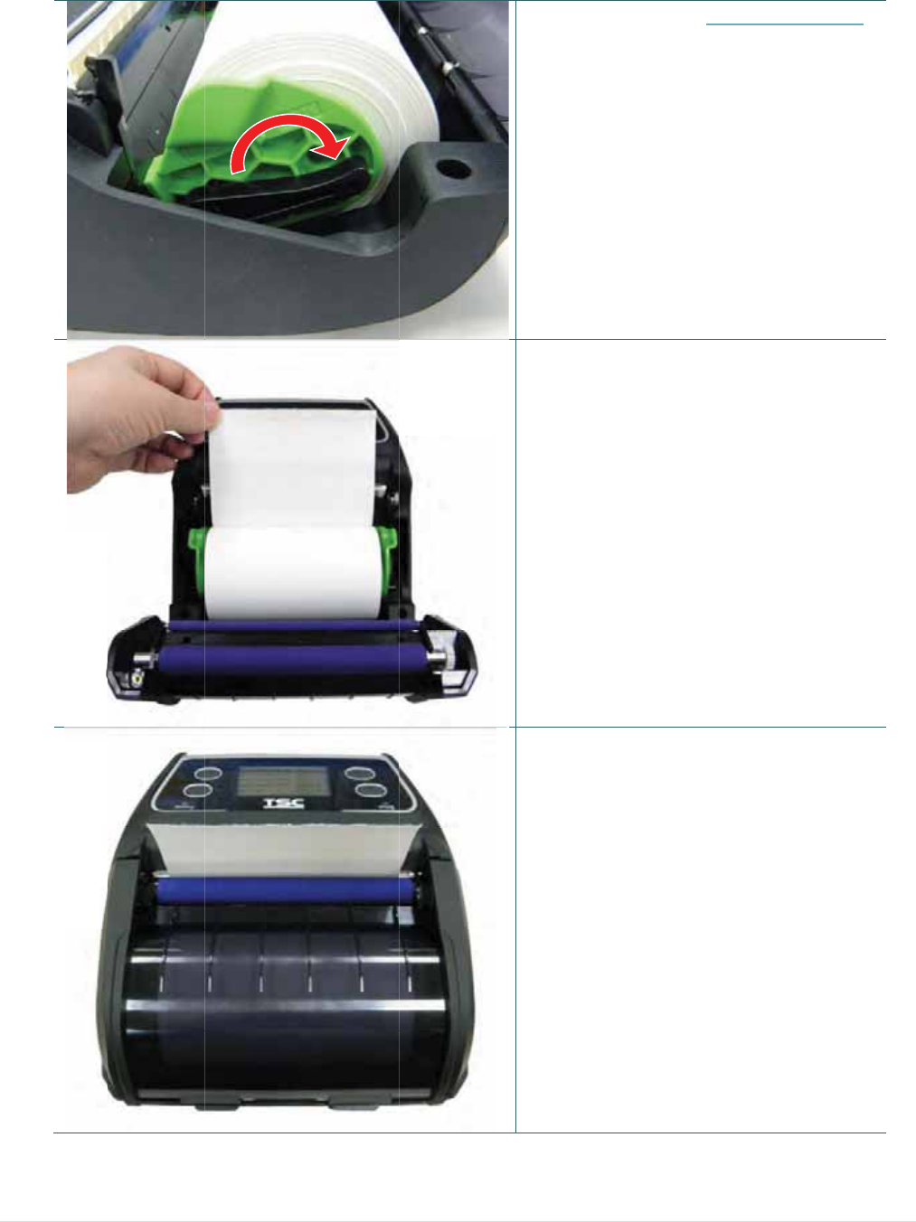
.3 Load
i
3
.3.1 Loa
d
i
ng the
M
d
ing the
M
M
edia
M
edia
- 14 -
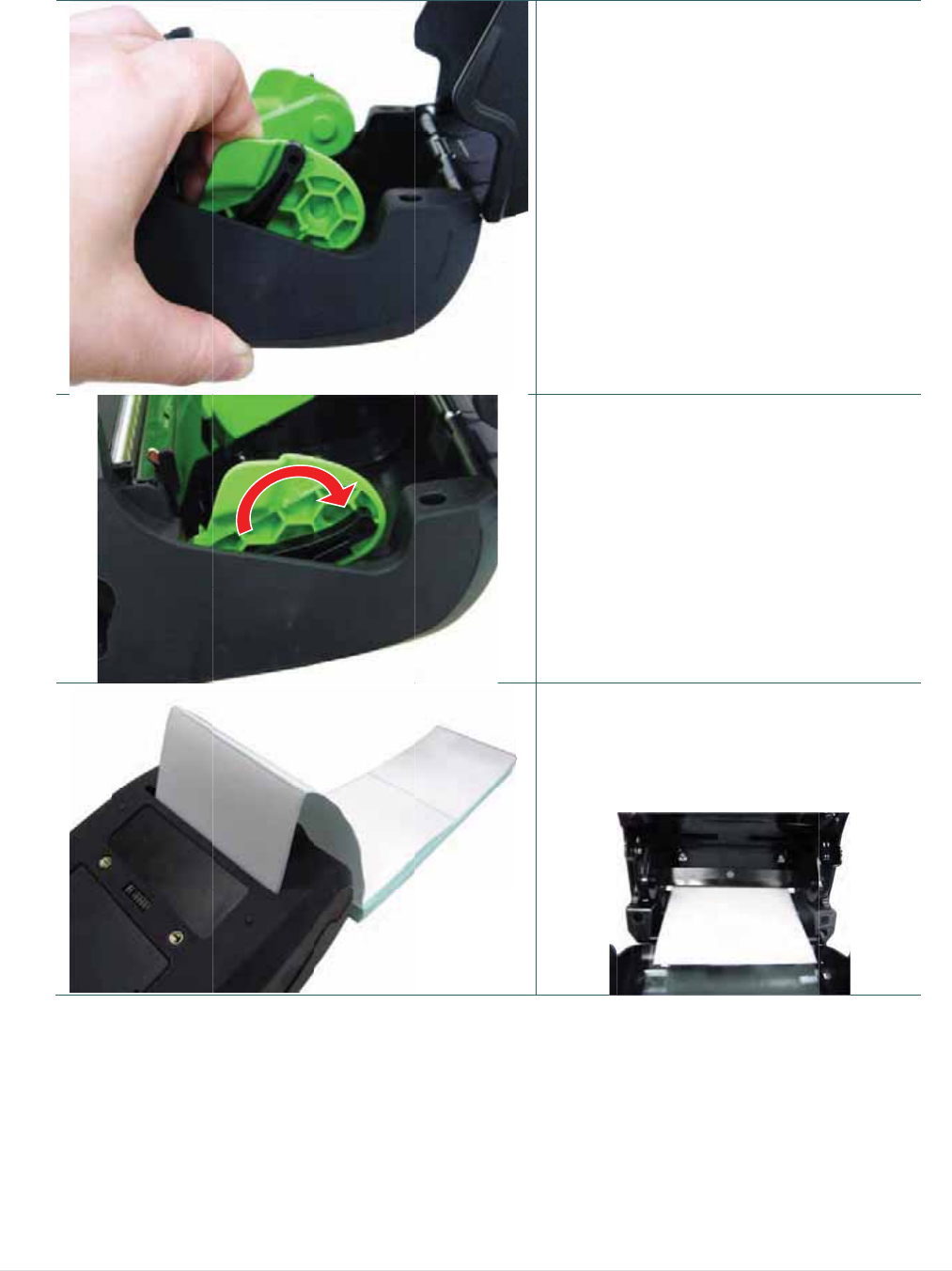
1.
2.
3.
Open th
e
cover by
media c
o
button.
Pull the
m
apart to
f
width.
Place th
e
media h
o
them on
t
the pap
e
face up,
enough
p
head.
e
printer
m
y
pressing
t
o
ver relea
s
m
edia hol
d
f
it the lab
e
e
roll betw
e
o
lders and
t
o the cor
e
e
r, printing
and pull o
p
aper ove
r
m
edia
t
he
s
e
d
ers
l roll
e
en the
close
e
. Place
side
u
t
r
the print

- 15 -
4. Press e
a
cover to
cover an
media c
o
correctly
Note:
* Please c
a
mark sen
media. T
u
open/clo
s
then it wi
sensor a
u
* Please r
e
YouTube
a
ch side o
f
close the
m
n
d make s
u
o
ver close
d
y
.
a
librate the
n
sor when c
u
rn on the
p
s
e the medi
i
ll calibrate
t
u
tomaticall
y
e
fer to vide
o
or driver C
f
media
m
edia
u
re the
d
gap/black
hanging
p
rinter and
a
cover
t
he
y
.
o
on TSC
D.
3
3
.3.2 Loa
d
d
ing Medi
a
a
in Peel-
o
o
ff Mode
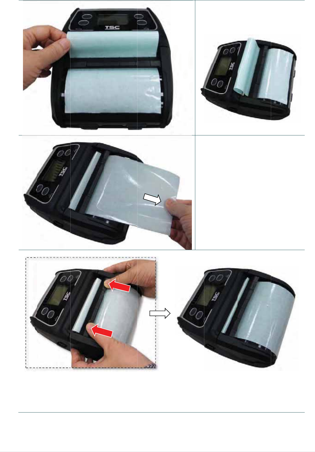
- 16 -
1.
2.
3.
Please r
e
3.3.1 to l
roll into t
Note:
Please cal
mark sens
media in p
on the pri
n
the media
calibrate t
h
automatic
a
Remove
the liner.
Press e
a
cover to
cover an
media c
o
correctly
e
fer to su
b
l
oading th
e
t
he printer.
ibrate the g
s
or after loa
d
p
eel-off mo
d
n
ter and op
e
cover then
h
e sensor
a
lly.
1~2 label
s
.
a
ch side o
f
close the
m
n
d make s
u
o
ver close
d
y
.
b
section
e
media
ap/black
d
ing
d
e. Turn
e
n/close
it will
s
from
f
media
m
edia
u
re the
d
6.
M
m
M
ove the p
m
odule. (c
o
eeler mod
u
o
ver the pl
a
u
le to nea
r
a
ten roller
)
- 17 -
r
the peel
e
)
4.
5.
e
r bar by p
u
Feed th
e
the peel
e
figure sh
Pull the l
u
shing ea
c
e
liner go t
h
e
r module.
h
own)
l
iner tightl
y
c
h side of
p
h
rough
(as
y
.
p
eeler
7.
P
Loo
s
P
ress dow
n
s
e the pee
l
n
the peel
e
l
er modul
e
e
r module
t
in the rev
e
- 18 -
t
o lock it.
erse proc
e
e
dures:
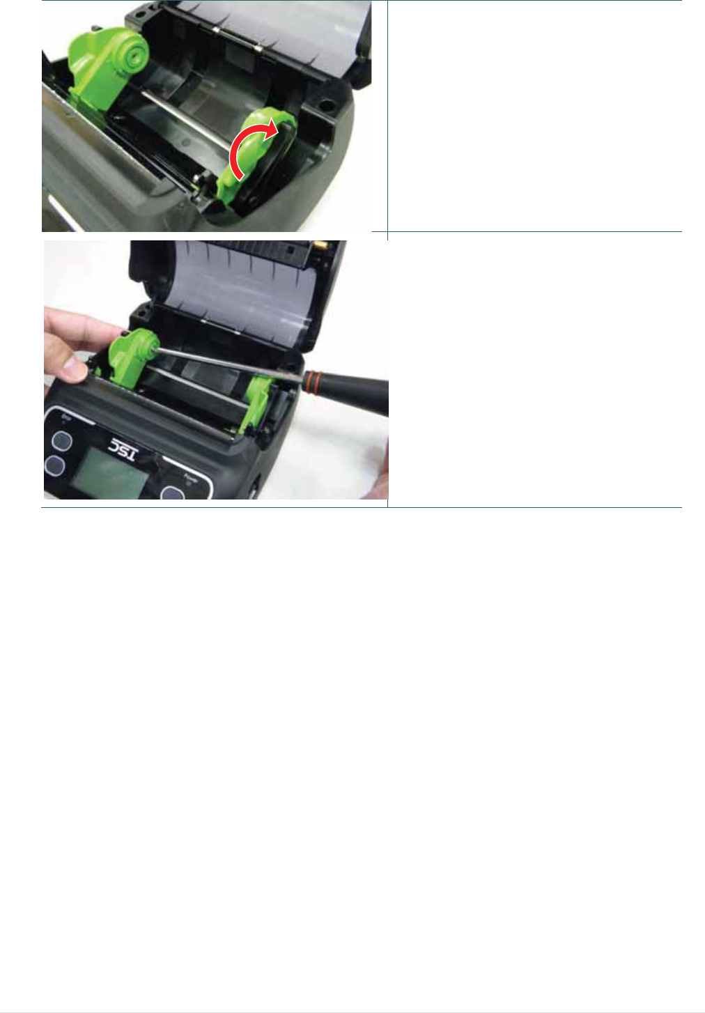
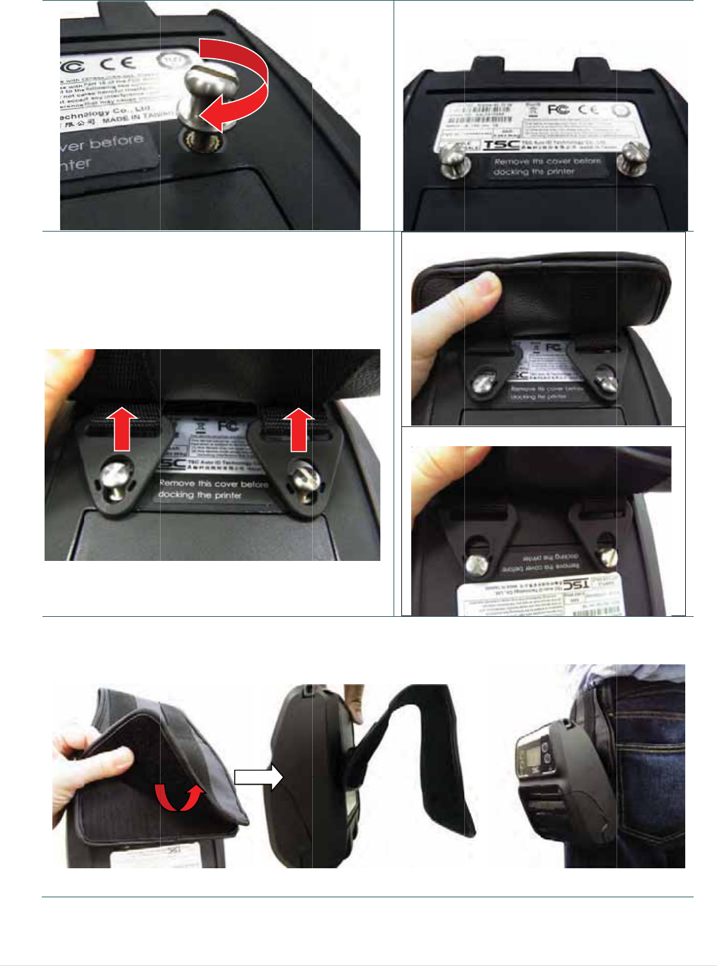
3
3
.3.3 Loa
d
d
ing the F
a
a
n-fold/E
x
x
ternal M
e
- 19 -
e
dia
1. Op
e
pre
s
rele
hol
d
wid
t
2. Pu
s
hol
d
me
d
3. Fe
e
ext
e
Pla
c
fac
e
e
n the prin
t
s
sing the
m
ase butto
n
d
ers apart
t
t
h.
s
h down e
a
d
er lock s
w
d
ia holder.
e
d the med
e
rnal label
c
e the pap
e
up.
t
er media
c
m
edia cov
e
n
. Pull the
to fit the
m
a
ch side o
f
w
itch to fix
d
ia through
entrance
c
er, printin
g
c
over by
e
r
m
edia
m
edia
f
media
t
he
the rear
c
hute.
g
side
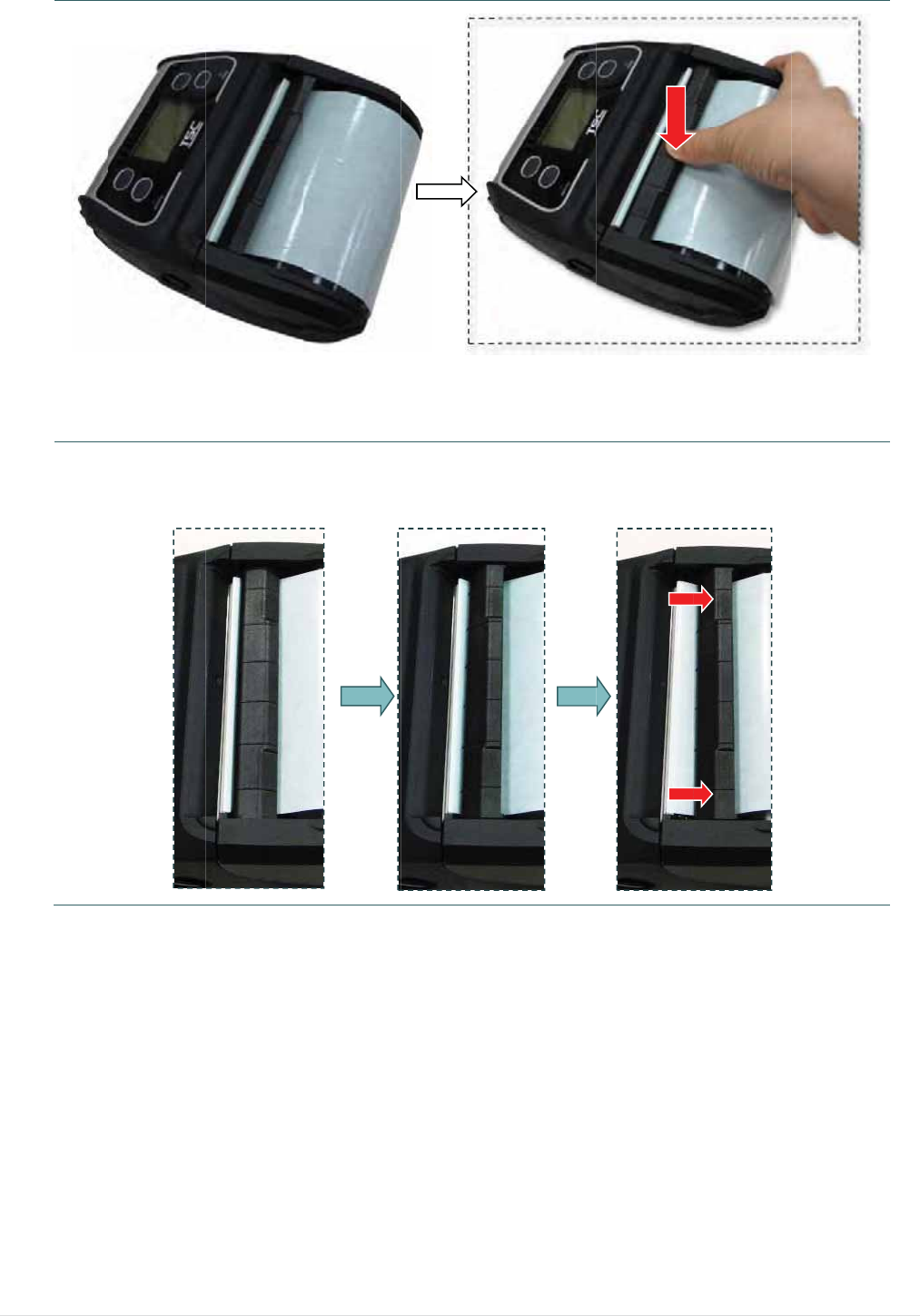
- 20 -
4. Pre
s
to c
ma
k
clo
s
Note
Plea
s
sens
on t
h
medi
sens
s
s each si
d
lose the
m
k
e sure th
e
s
ed correc
t
:
s
e calibrate
o
r when ch
a
h
e printer a
n
a cover the
n
o
r automati
d
e of med
i
m
edia cove
e
media c
o
t
ly.
the gap/bl
a
a
nging me
d
n
d open/clo
s
n it will cali
b
cally.
i
a cover
r
and
o
ver
a
ck mark
d
ia. Turn
s
e the
b
rate the
3
3
.3.4 Loa
d
d
ing the L
i
i
nerless
M
edia (Opt
i
- 21 -
i
on)
1. Ple
a
to l
o
prin
2. Pu
s
hol
d
me
d
me
d
3. Pla
c
fac
e
pa
p
4. Pre
s
to c
ma
k
clo
s
Note
Plea
s
sens
on t
h
medi
sens
a
se refer t
o
o
ading the
ter.
s
h down e
a
d
er lock s
w
d
ia holde
r
f
d
ia.
c
e the pap
e
up, and
p
er over th
e
s
s each si
d
lose the
m
k
e sure th
e
s
ed correc
t
:
s
e calibrate
o
r when ch
a
h
e printer a
n
a cover the
n
o
r automati
o
subsecti
o
media roll
a
ch side o
f
w
itch to fix
f
or using li
er, printin
g
p
ull out en
o
e
print he
a
d
e of med
i
m
edia cove
e
media c
o
t
ly.
the gap/bl
a
a
nging me
d
n
d open/clo
s
n it will cali
b
cally.
o
n 3.3.1
into the
f
media
t
he
nerless
g
side
o
ugh
d.
i
a cover
r
and
o
ver
a
ck mark
d
ia. Turn
s
e the
b
rate the
3
3
3
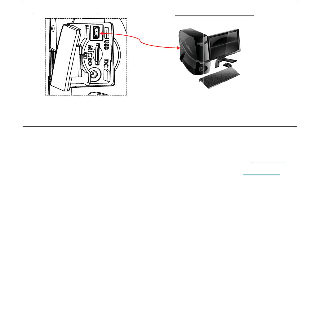
3
.4 Conn
The
p
be pri
*
*
3
.4.1 Cabl
Op
e
(ho
3
.4.2 Wir
e
Y
ou
s
setti
n
WLA
N
U
ecting t
h
p
rinter mu
s
nted. The
r
By a cabl
e
By a Wir
e
e Commu
n
e
n the int
e
st termina
e
less Com
s
hould set
t
n
g the Wi-Fi
N settings.
SB connect
o
h
e Print
e
s
t establis
h
r
e are thre
e
e
between
e
less LAN
(
n
ications
e
rface cov
e
l) with US
B
municati
o
t
he WLAN s
e
module. If
y
o
r (Printer)
e
r
communi
c
e
ways to
c
the printe
r
(
Option)
e
r and con
n
B
cable. (
U
o
ns with
W
e
ttings via
t
y
our printe
r
- 22 -
c
ation wit
h
c
onnect f
o
r
and its h
o
nect the p
r
U
SB to US
B
W
i-Fi (Opti
t
he cable fo
r
supports t
h
a host te
r
o
r Alpha-4
L
o
st termin
a
r
inter to th
e
B
or USB
t
on)
r first usin
g
he LCD, pl
e
USB/RS-2
r
minal whi
c
L
series,
a
l
e
compute
t
o RS-232
)
g
. Please re
f
e
ase refe
r
t
h
32 connecto
c
h sends t
er
/smart p
h
)
f
er to sectio
h
esection 6
o
r (PC)
h
e data to
h
one
n 5.4 to
.
3.4 to set t
h
h
e
3
3
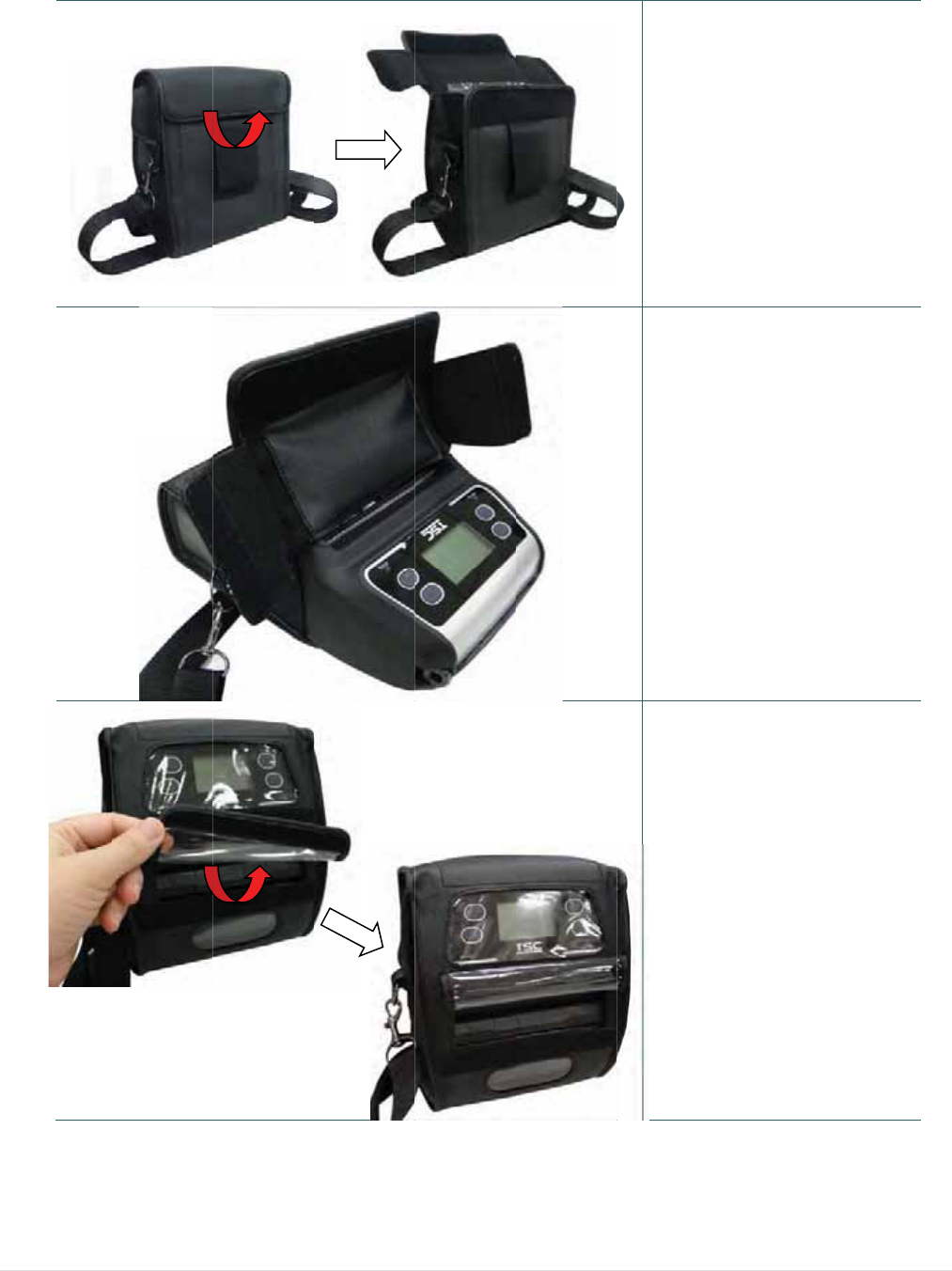
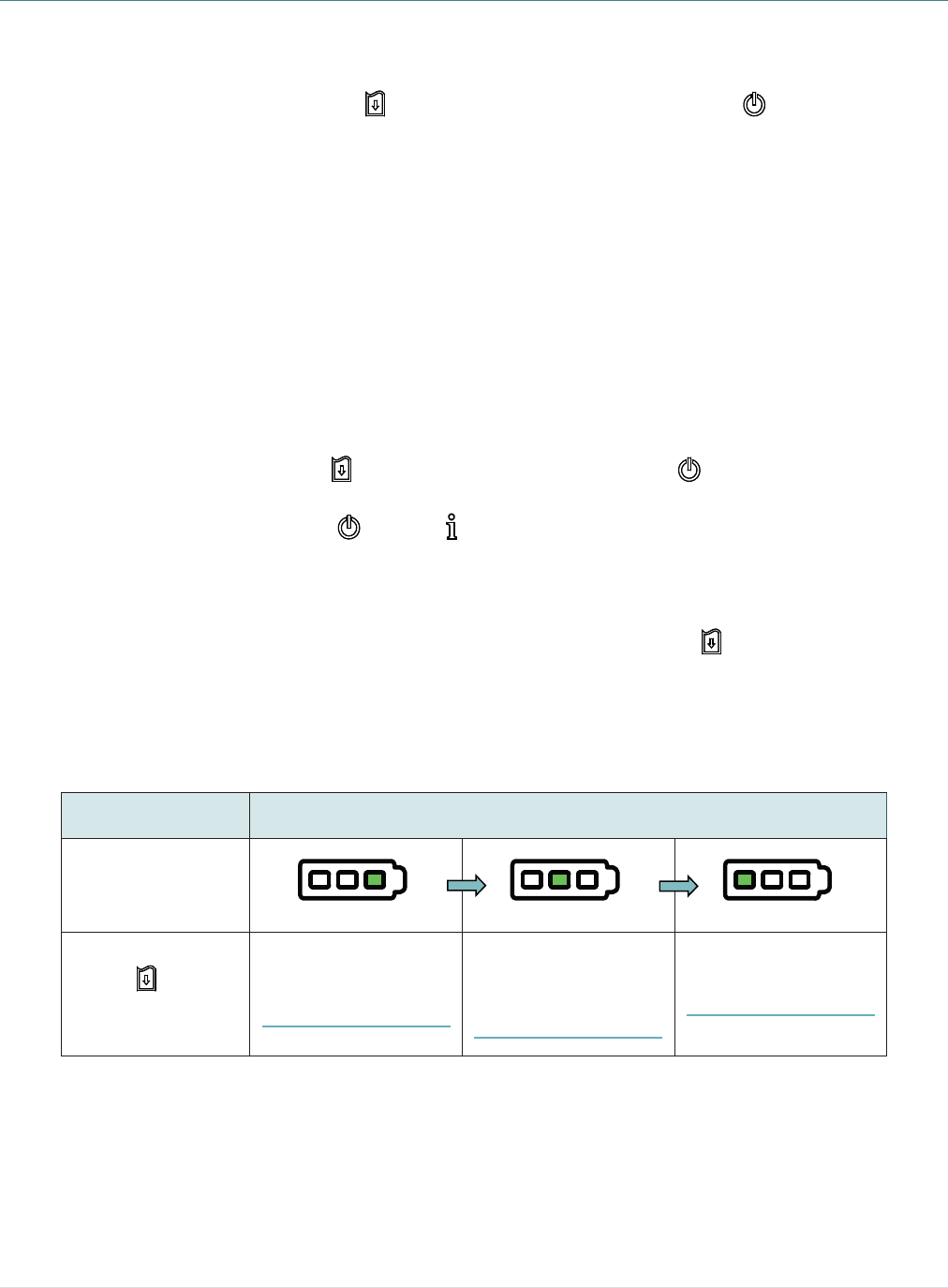
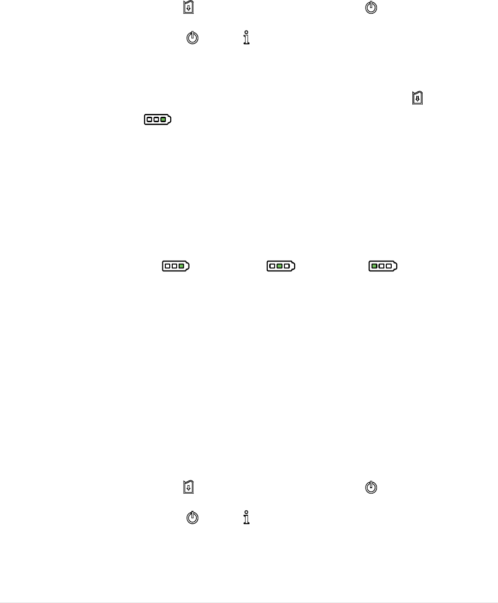
.5 Install the IP
5
5
4-rated Environ
- 23 -
mental
C
C
ase wit
h
h
Should
e
1. Op
e
co
v
2. Pu
t
ca
s
3. Cl
o
co
v
co
v
op
e
e
r Strap
en the ca
s
v
er.
t
the print
e
s
e.
o
se the ca
s
v
er. The o
u
v
er should
e
ned whil
e
(Option
)
s
e top
er
into the
s
e top
u
tside
be
printing.
)
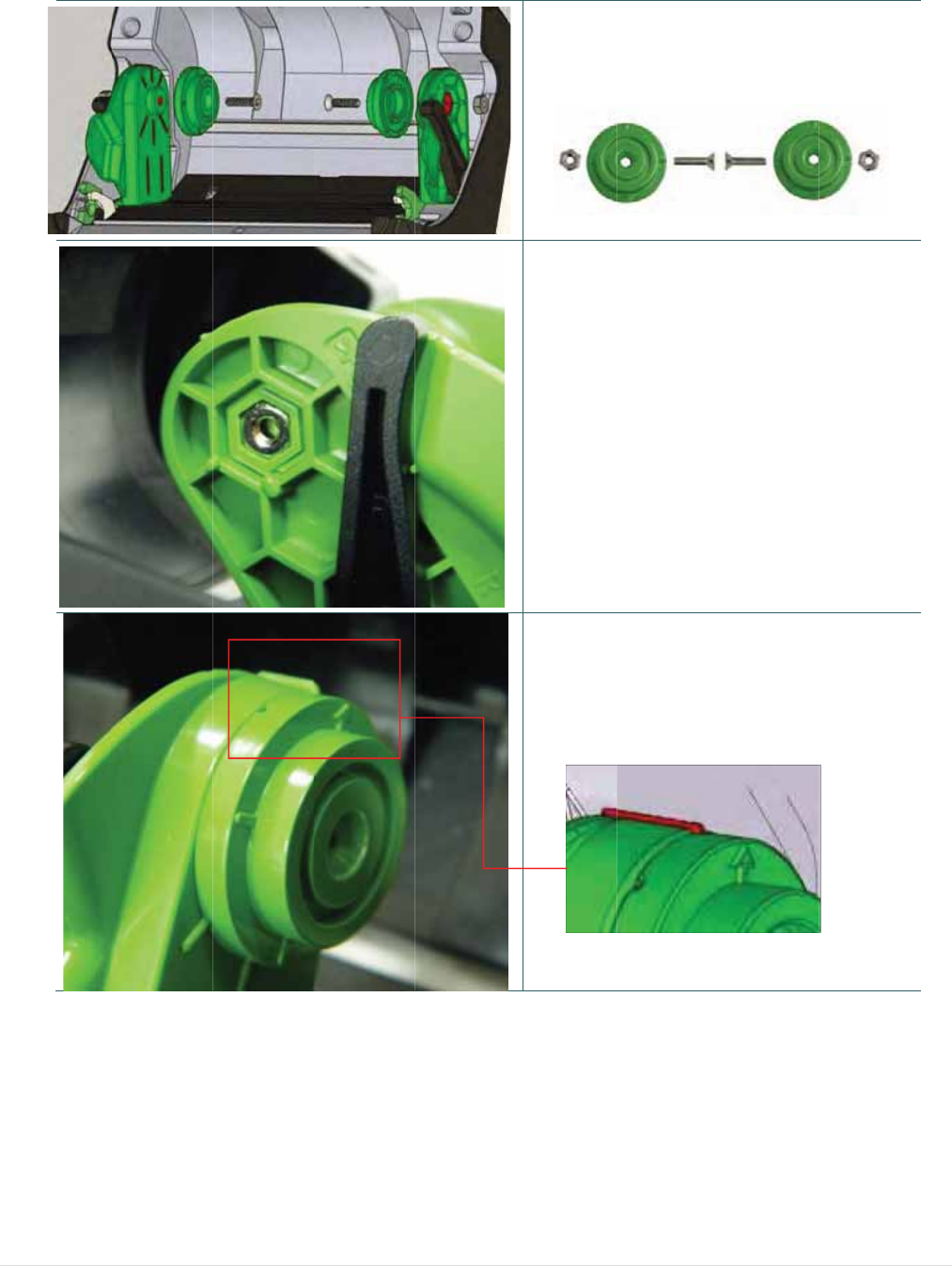
3
3
.6 Install the A
d
d
apter for 0.75”
a
- 24 -
a
nd 1”
P
P
aper Co
r
1. Che
c
A
S
N
2. Put t
h
3. Mak
e
to in
s
r
e (Opti
o
c
k the part
s
dapter x 2
crew x 2
ut x 2
h
e nut on
t
e
the arro
w
s
tall the ad
o
n)
s
.
t
he media
w
direction
apter.
holde
r
.
is as fig.
- 25 -
4. Pull the media holders apart.
Push down another side of media
holder lock switch to keep the
media holder in max width.
5. Tighten the screw on nut for fixing
the adapter on media holder.
Note: Press the nut with hand when
tighten the screw.
3
3
.7 Insta
2.
P
s
3.
O
ll the Be
P
ull up th
e
s
crews.
O
pen the
b
lt Strap
e
belt strap
b
elt strap f
o
(
Option/
to lock it
o
o
r using.
- 26 -
Standa
r
o
n the
r
d for lin
e
1. Tigh
For lin
e
For sta
n
e
rless m
o
ten 2 scre
w
rless mod
e
n
dard mo
d
odel)
w
s on the
e
l
d
el
printer.

- 27 -
- 28 -
4. Power-on Utilities
There are three power-on utilities to set up and test printer hardware. These utilities are
activated by pressing FEED button ( ) then turning on the printer power ( ) simultaneously
and release the button at different positions of LED indicator.
4.1 Power-on Utility for Standard Panel
Please follow the steps below for different power-on utilities.
1. Turn off the printer power switch.
2. Hold on the FEED button ( ) then turn on the power switch ( ).
3. Release the power switch ( ) when LED color turn on amber.
Note: In this moment, you should still hold on the FEED button.
4. The printer will beep sound twice later, then release the button ( ) when battery LED
indicates with different positions for each function.
Power on utilities
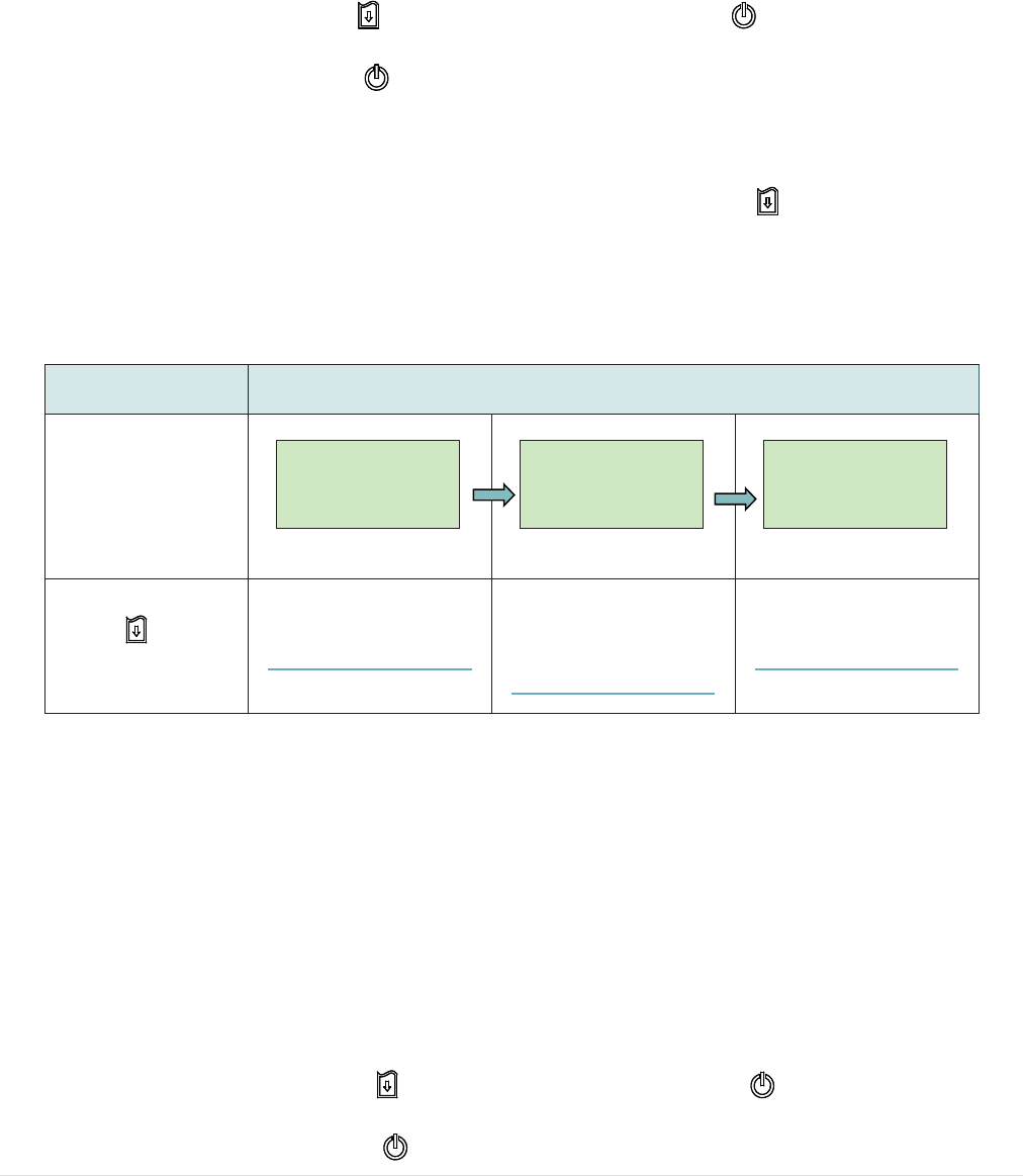
for standard panel The battery LED light will be changed as following.
LED
(5 blinks)
(5 blinks)
(5 blinks)
Release FEED
button ( ) for
different functions
Media sensor
calibration
(Please refer to 4.1.1)
Media sensor
calibration, self-test
and enter dump mode
(Please refer to 4.1.2)
Printer initialization
(Please refer to 4.1.3)
- 29 -
4.1.1 Media Sensor Calibration
Please follow the steps below to calibrate the media sensor.
1. Turn off the printer power switch.
2. Hold on the FEED button ( ) then turn on the power switch ( ).
3. Release the power switch ( ) when LED color turn on amber.
Note: In this moment, you should still hold on the FEED button.
4. The printer will beep sound twice later, then release the FEED button ( ) when the
indicator becomes and blinking.
5. Printer will calibrate the gap/black mark sensor sensitivity.
Note: You also can do this function by open/close the media cover when turn on the
printer.
The LEDs will be changed as following figures:
Beep sound twice Æ(5 blinks) Æ (5 blinks) Æ (5 blinks) Æ Turn
on the printer
4.1.2 Self-test and Dump Mode
Please follow the steps below.
1. Turn off the printer power switch.
2. Hold on the FEED button ( ) then turn on the power switch ( ).
3. Release the power switch ( ) when LED color turn on amber.
Note: In this moment, you should still hold on the FEED button.
- 30 -
4. The printer will beep sound twice later, then release the FEED button ( ) when the
indicator becomes and blinking.
5. Printer will calibrate the sensor and print out the internal settings, then enter the dump
mode.
Note: Turn off/on the power or press FEED button to resume printer from dump mode
to normal printing mode. Please refer to sections 4.3 and 4.4 for more details of
self-test and dump mode.
The LEDs will be changed as following figures:
Beep sound twice Æ(5 blinks) Æ (5 blinks) Æ (5 blinks) Æ Turn
on the printer
4.1.3 Printer Initialization
Printer initialization is used to clear DRAM and restore printer settings to defaults.
Printer initialization is activated by the following procedures.
1. Turn off the printer power switch.
2. Hold on the FEED button ( ) then turn on the power switch ( ).
3. Release the power switch ( ) when LED color turn on amber.
Note: In this moment, you should still hold on the FEED button.
4. The printer will beep sound twice later, then release the FEED button ( ) when the
indicator becomes and blinking.
5. Printer will restore printer settings to defaults.
Note: Please refer to section 4.5 for printer defaults.
The LEDs will be changed as following figures:
Beep sound twice Æ(5 blinks) Æ (5 blinks) Æ (5 blinks) Æ Turn
on the printer
- 31 -
4.2 Power-on Utility for LCD Panel (Option)
Please follow the steps below for different power-on utilities.
1. Turn off the printer power switch.
2. Hold on the FEED button ( ) then turn on the power switch ( ).
3. Release the power switch ( ) when “Error” LED color turn on red.
Note: In this moment, you should still hold on the FEED button.
4. The printer will beep sound twice later, then release the button ( ) when LCD indicate
for different functions.
4.2.1 Media Sensor Calibration
Please follow the steps below to calibrate the media sensor.
1. Turn off the printer power switch.
2. Hold on the FEED button ( ) then turn on the power switch ( ).
3. Release the power switch ( ) when “Error” LED color turn on red.
Power on utilities
for LCD panel The LCD will be changed as following.
LCD
Calibrate…..
(5 dots)
Self Test…..
(5 dots)
Initialize…..
(5 dots)
Release FEED
button ( ) for
different functions
Media sensor calibration
(Please refer to 4.2.1)
Media sensor
calibration, self-test and
enter dump mode
(Please refer to 4.2.2)
Printer initialization
(Please refer to 4.2.3)

- 32 -
Note: In this moment, you should still hold on the FEED button.
4. The printer will beep sound twice later, then release the FEED button ( ) when LCD
showing “Calibrate…..”.
5. Printer will calibrate the gap/black mark sensor sensitivity.
Note: You also can do this function by open/close the media cover when turn on the
printer.
The LCD will be changed as following:
Beep sound twice ÆCalibrate….. (5 dots) Æ Self Test….. (5 dots) Æ Initialize….. (5
dots) Æ Turn on the printer
4.2.2 Self-test and Dump Mode
Please follow the steps below.
1. Turn off the printer power switch.
2. Hold on the FEED button ( ) then turn on the power switch ( ).
3. Release the power switch ( ) when “Error” LED color turn on red.
Note: In this moment, you should still hold on the FEED button.
4. The printer will beep sound twice later, then release the FEED button ( ) when LCD
showing “Self Test…..”.
5. Printer will calibrate the sensor and print out the internal settings, then enter the dump
mode.
Note: Turn off/on the power or press FEED button to resume printer for normal printing.
(Ready mode) Please refer to sections 4.3 and 4.4 for more details.
The LCD will be changed as following figures:

- 33 -
Beep sound twice ÆCalibrate….. (5 dots) Æ Self Test….. (5 dots) Æ Initialize….. (5
dots) Æ Turn on the printer
4.2.3 Printer Initialization
Printer initialization is used to clear DRAM and restore printer settings to defaults.
Printer initialization is activated by the following procedures.
1. Turn off the printer power switch.
2. Hold on the FEED button ( ) then turn on the power switch ( ).
3. Release the power switch ( ) when “Error” LED color turn on red.
Note: In this moment, you should still hold on the FEED button.
4. The printer will beep sound twice later, then release the FEED button ( ) when the
LCD showing “Initialize…..”.
5. Printer will restore printer settings to defaults.
Note: Please refer to section 4.5 for printer defaults.
The LCD will be changed as following figures:
Beep sound twice ÆCalibrate….. (5 dots) Æ Self Test….. (5 dots) Æ Initialize….. (5
dots) Æ Turn on the printer
- 34 -
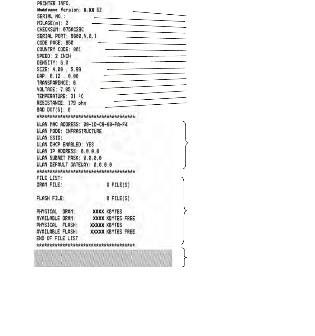
4.3 Self-test
Printer will print the printer configuration after media sensor calibration. Self-test
printout can be used to check if there is any dot damage on the heater element,
printer configurations and available memory space.
Note: Self-test printout requires 4” wide paper width.
Printer model name & Main board firmware version
Printer serial number
Printed mileage
Main board firmware checksum
Serial port setting
Code page
Country code
Print speed
Print darkness
Label size (width, height)
Gap/Black mark (vertical gap, offset)
Sensor sensitivity
Battery voltage
Print head temperature
Print head average resistance
Bad dots of print head
WiFi settings information (option)
File management information
Print head test pattern
- 35 -
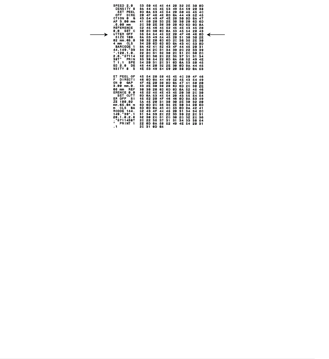
4.4 Dump mode
Printer will enter dump mode after printing printer configuration. In the dump mode, all
characters will be printed in 2 columns as following. The left side characters are
received from your system and right side data are the corresponding hexadecimal
value of the characters. It allows users or engineers to verify and debug the program.
Note:
1. Dump mode requires 4” wide paper width.
2. Turn off / on the power or press FEED button to resume printer for normal printing.
(Ready mode)
ASCII Data Hex decimal data related to left
column of ASCII data

- 36 -
4.5 Printer defaults
Printer configuration will be restored to defaults as below after initialization.
Parameter Default setting
Speed 50.8 mm/sec (2 ips)
Density 8
Media Width 4” (101.5 mm)
Media Height 4” (101.5 mm)
Sensor Type Gap sensor
Print Direction 0
Reference Point 0,0 (upper left corner)
Gap Offset 0
Post-Print Action Tear mode
Serial Port Settings 9600 bps, none parity, 8 data bits, 1 stop bit
Code Page 850
Country Code 001
Clear Flash Memory No
Note:
When printer initialization is done, please calibrate the gap or black mark sensor before
printing.
- 37 -
5. Diagnostic Tool
TSC’s Diagnostic Utility is an integrated tool incorporating features that enable you to
explore a printer’s settings/status; change a printer’s settings; download graphics, fonts
and firmware; create a printer bitmap font; and send additional commands to a printer.
With the aid of this powerful tool, you can review printer status and setting in an instant,
which makes it much easier to troubleshoot problems and other issues.
5.1 Start the Diagnostic Tool
1. Double click on the Diagnostic tool icon to start the software.
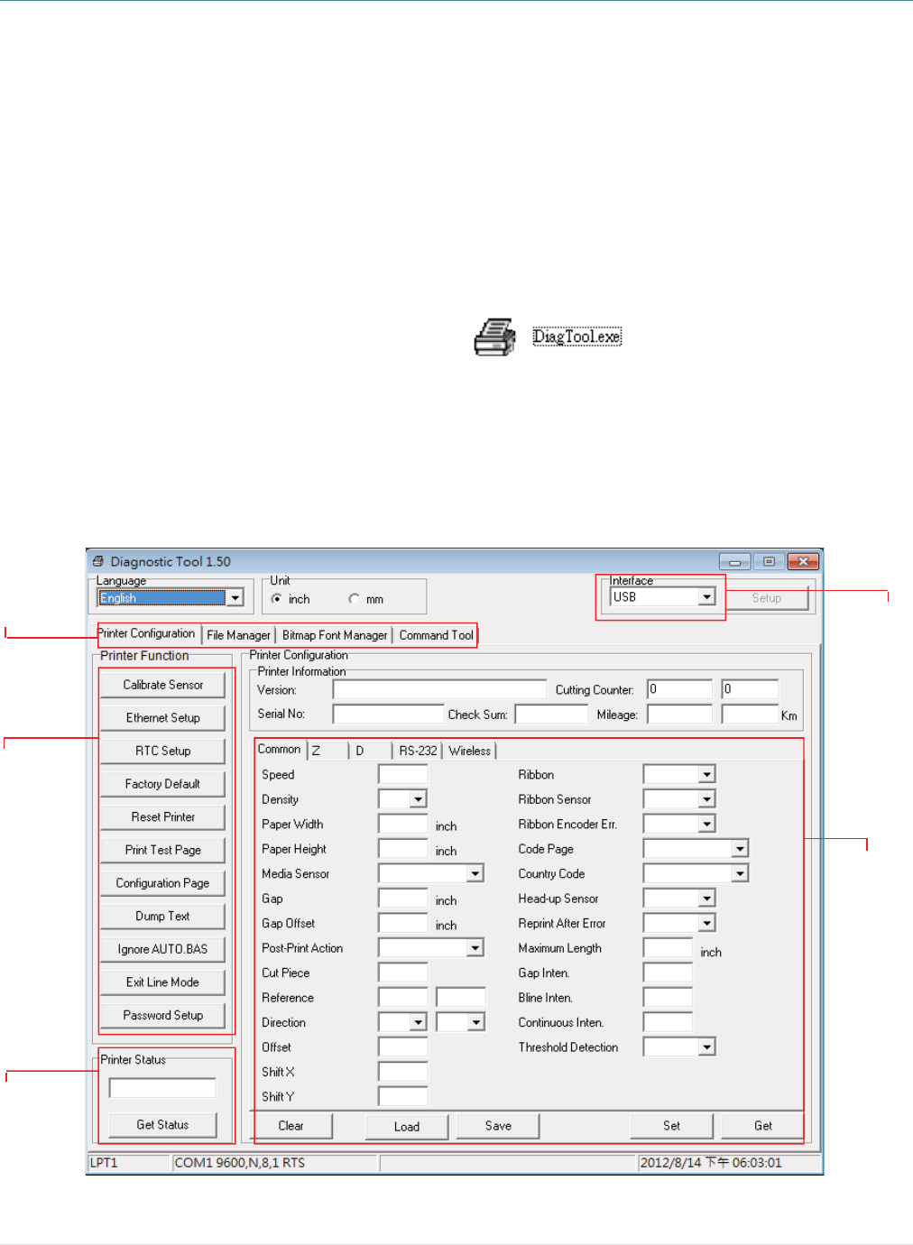
2. There are four features (Printer Configuration, File Manager, Bitmap Font Manager,
Command Tool) included in the Diagnostic utility.
Features tab
Printer
functions
Interface
Printer Status
Printer setup
5
5
.2 Print
1. C
o
N
2. S
e
U
T
i
c
s
i
3. Cl
4. T
h
Fo
r
gui
d
er Func
t
o
nnect the
N
ote:
* The print
e
(option).
e
lect the P
U
SB to US
B
T
he default i
n
nterface. If
U
c
onnected w
s
ettings nee
d
nterface fiel
d
ick the “P
r
h
e detail f
u
r
more infor
de in the C
D
t
ion
printer an
e
r connects
C interfac
e
B
cable
n
terface sett
U
SB interfac
e
ith printer, n
o
d
to be chan
g
d
.
r
inter Func
u
nctions in
F
C
E
R
F
R
P
C
D
I
g
E
P
mation abo
u
D
disk \ Utili
d comput
e
with the co
m
e
connect
e
ing is USB
e
is
o
other
g
ed in the
t
ion” butto
the Printe
r
unction
C
alibrate Sen
thernet Set
u
R
TC Setup
actory Defa
u
R
eset Printer
rint Test Pa
g
C
onfiguration
D
ump Text
g
nore AUTO
.
xit Line Mod
assword Se
t
u
t Diagnost
ties directo
- 38 -
e
r with a c
a
mputer via
U
e
d with ba
r
USB to R
S
n to setup
.
r
Function
D
e
n
sor C
a
S
e
u
p S
e
th
e
S
y
u
lt In
i
fa
c
R
e
g
e P
r
Page P
r
T
o
.BAS Ig
n
d
e E
x
t
up S
e
t
ic Tool, ple
a
ry.
a
ble.
U
SB to US
B
r
code prin
t
S
-232 cable
.
Group ar
e
e
scription
a
librate the
s
e
tup group
m
e
tup the IP a
e
on board
E
y
nchronize p
tialize the p
r
c
tory default
e
boot printer
r
int a test pa
g
r
int printer c
o
o
activate th
e
n
ore the do
w
x
it line mode
e
t the passw
o
a
se refer to
1
B
cable or U
S
t
e
r
.
e
listed as
b
ensor speci
f
m
edia sensor
d
dress, sub
n
E
thernet
r
inter Real
T
r
inter and re
s
.
g
e
o
nfiguration
e
printer du
m
w
nloaded AU
.
o
rd to prote
c
the diagno
s
2
SB to RS-2
3
below.
f
ied in the P
r
r
field
n
et mask, g
a
T
ime Clock
w
s
tore the set
t
m
p mode.
U
TO.BAS pr
o
c
t the setting
s
tic utility q
3
2 cable
r
inter
a
teway for
w
ith PC
t
ings to
o
gram
s
uick start
- 39 -
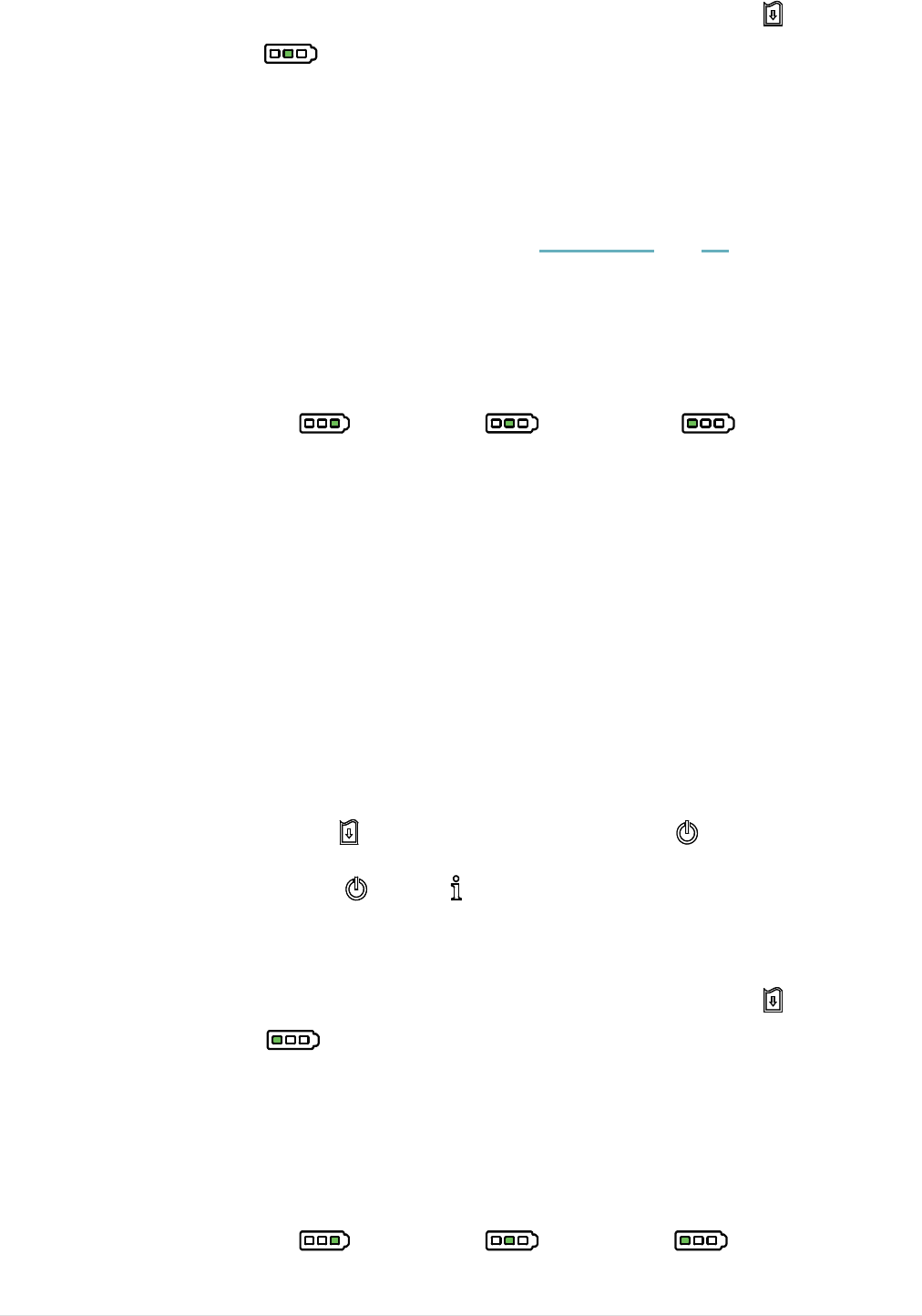
5.4 Setting Wi-Fi by Diagnostic Tool (Option)
1. Connect the printer and computer with the cable.
Note:
* The printer connects with the computer via USB to USB cable or USB to RS-232 cable
(option).
2. Turn on the printer power switch.
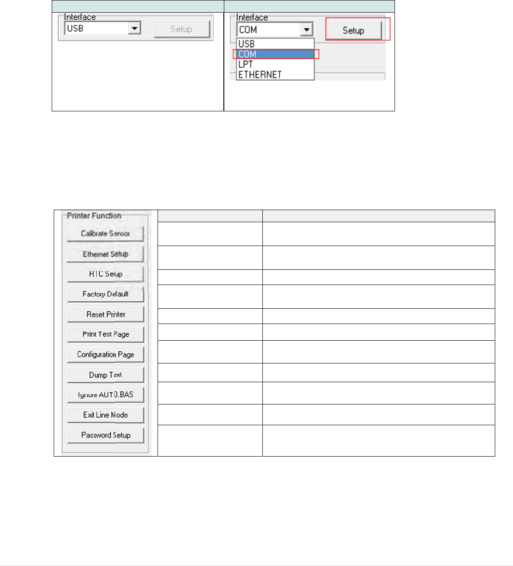
3. Open Diagnostic tool and set interface. (The default setting is USB.)
USB to USB cable USB to RS-232 cable
The default interface setting is USB
interface. If USB interface is
connected with printer, no other
settings need to be changed in the
interface field.
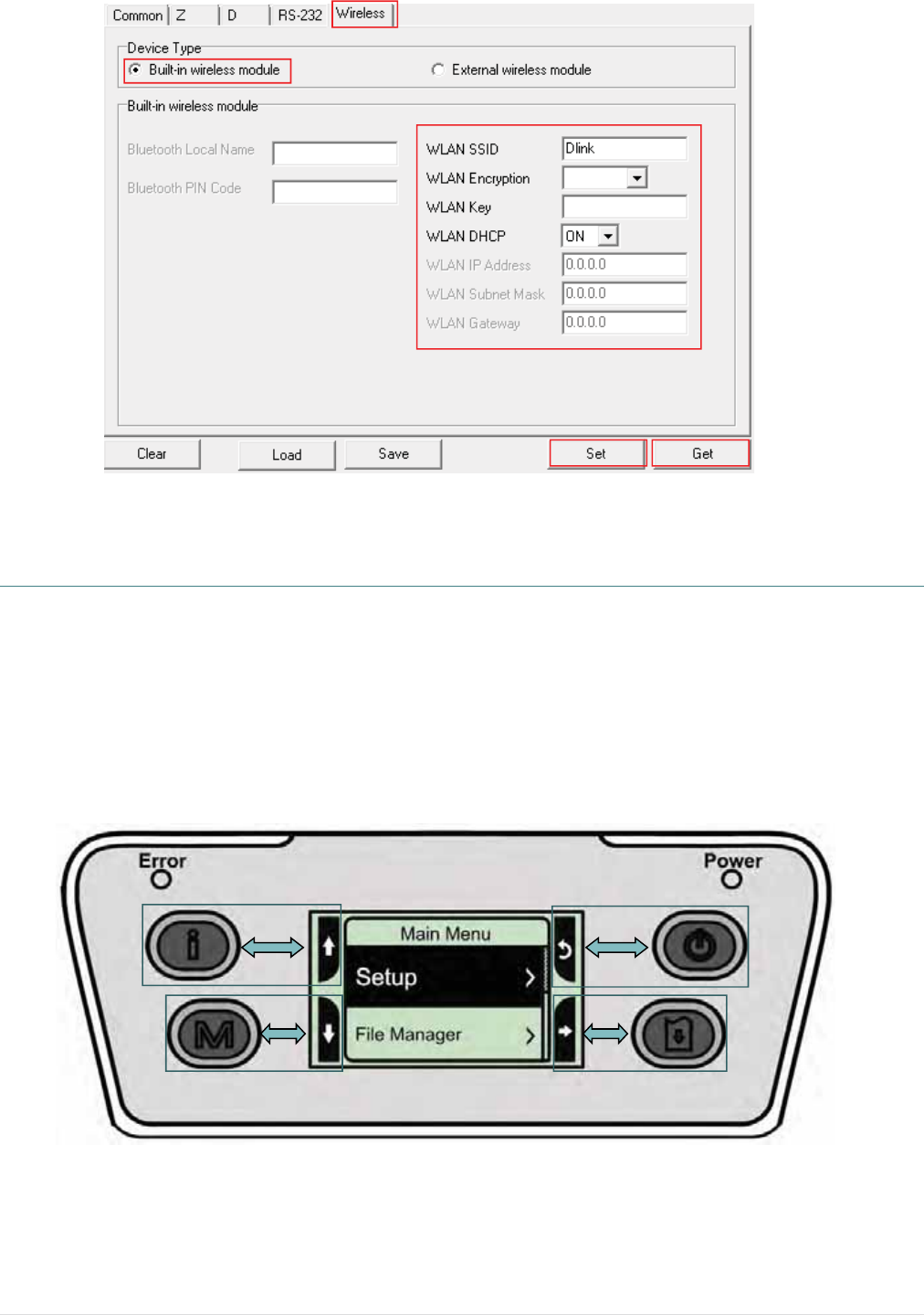
4. Select “Wireless” tab and click on “Built-in wireless module” item.
5. Enter the new WLAN settings in the editor.
6. Press “Set” button to set the new settings to the printer.
7. The Wi-Fi LED will turn on blue (the Wi-Fi icon will be shown for LCD panel) if device
has been connected.
8. Print out the self-test page to confirm if it’s connected with right settings.
9. Remove the cable to print a data for test.
1
2
- 40 -
6. LCD Menu Function (Option)
The Alpha-4L series offer the LCD panel for selection to further enhance its capabilities to meet the
demands of a wide range of printing solutions. This option feature includes LCD control panel, 4
buttons and 2 LED display. Please press the “M” button to enter the setting menu.
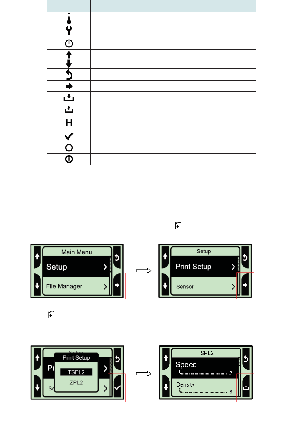
6.1 How to use the LCD to set the printer
Press the “M” button to display the function menu screen as following shown.
You can use this 4 buttons to scroll, select, enter or return the menu, depend on the icons from 4-
sides of LCD. It was selected if the item with the black ground on the screen. The icon function is
listed as below,
1
2
3
4 5
- 41 -
Icon Function
Display printer information
Enter setting menu
Power switch
Scroll up
Scroll down
Return to previous menu
Enter to next menu
Enter setting mode
Exit setting mode
Save the selected settings and return to previous
menu
Select
Alter to OFF
Alter to ON
For example:
Change the speed setting, please following steps as below.
1. Press “M” button to enter the setting menu. Press button to enter the “Setup” item.
2. Press button to enter the “Print Setup” item. Select the “TSPL2” item. Enter the “Speed”
setting mode.
- 42 -
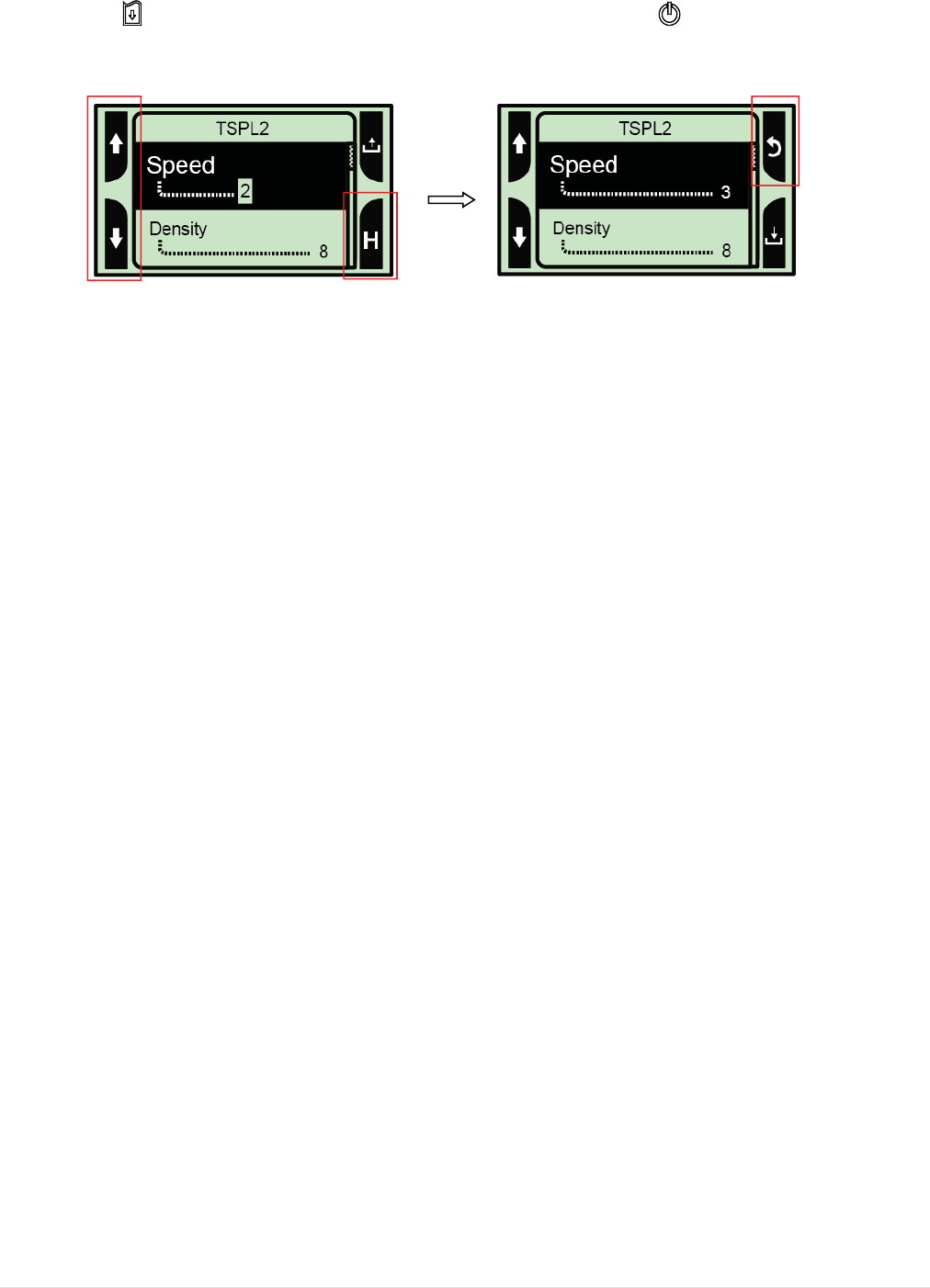
3. At this status, you can scroll up or scroll down to select the value of print speed. Then press
the button to save the selected value into the printer. Press “ ” butter to back to “Ready
mode”.
- 43 -
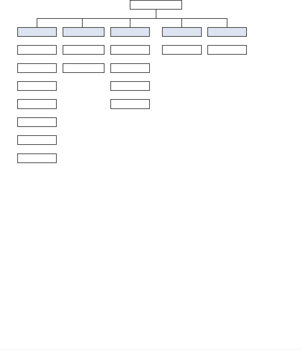
6.2 Main Menu Overview
There are 5 categories for the main menu. You can easy to set the settings of printer without
connecting the computer. Please refer to following sections for more details.
ɧ
Date Time
Display
ɧ
Bluetooth
Print Head
*Wireless
LAN
ɧ
ɧɧ
Serial Battery
ɧɧ
Dump Mode
Initialization
ɧɧɧ
Sensor FLASH
Service
ɧɧɧ ɧɧ
Main Menu
Setup File Manager Diagnostics Language
Printer DRAM Print Config. English
Note:
* The Wireless LAN function is optional for Alpha-4L series.
6
6
6
.3 Setu
p
This “
S
settin
g
6
.3.1 Prin
t
6.3.1-1
P
Item
Spee
d
Densi
t
Direc
t
p
S
etup” cate
g
g
s.
t
er Setup
P
rinter se
t
d
t
y
t
ion
Main
M
g
o
r
y can s
e
t
up for T
S
Descripti
Use this i
t
0.5 ips. A
v
Use this
o
from 0 to
based on
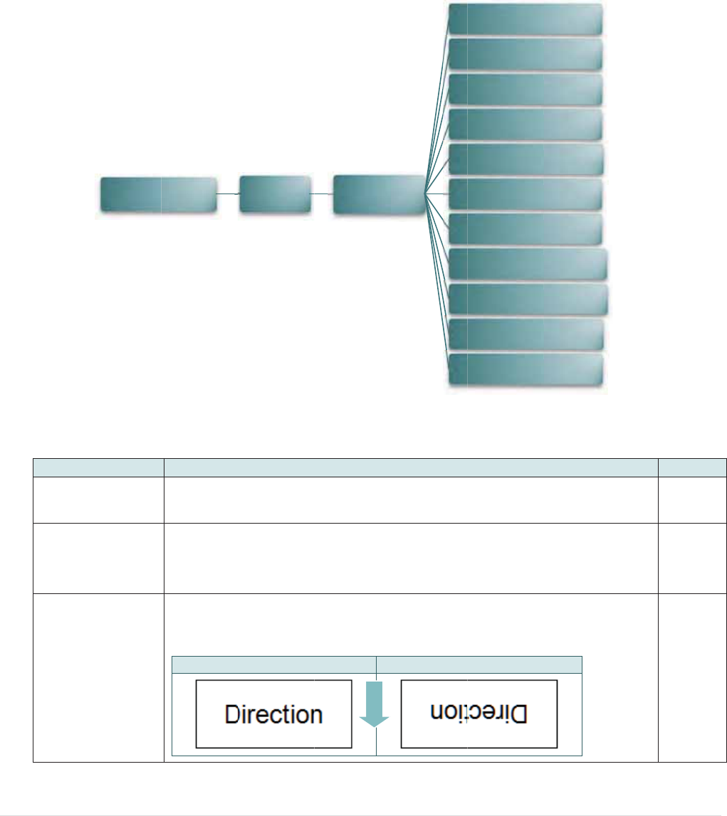
The direc
t
printout d
D
M
enu
e
t up the se
S
PL2
on
t
em to setu
v
ailable se
t
o
ption to se
t
15, and th
e
selected
m
t
ion setting
irection.
D
IRECTION
0
Setup
- 44 -
nsor, serial
p print spe
e
t
ting is fro
m
t
up printing
e
step is 1.
Y
m
edia.
value is ei
t
0
TSP
L
FEED
comm., wi
r
e
d. The ea
c
m
1 to 6.
darkness.
Y
ou may n
e
t
her 1 or 0.
DIR
E
L
2
r
eless, dat
e
c
h inc
r
ease
The availa
b
e
ed to adju
s
Use this ite
CTION 1
Spee
d
Densit
y
Directi
o
Print M
o
Offse
t
Shift
X
Shift
Y
Referen
c
Referen
c
Code P
a
Count
r
e
time and
d
or decreas
b
le setting i
s
s
t your den
s
e
m to setup
d
t
y
o
n
o
de
t
X
Y
c
e X
c
e Y
a
ge
r
y
d
isplay
Def
a
e is 2
s
s
ity 8
the
0
a
ult

- 45 -
Print mode
This item is used to set the print mode. There are 3 modes as below,
Printer Mode Description
None Next label top of form is aligned to the print
head burn line location. (Tear Off Mode)
Batch Mode
Once image is printed completely, label
gap/black mark will be fed to the tear plate
location for tear away.
Peeler Mode Enable the label peel off mode.
Batch
Mode
Offset This item is used to fine tune media stop location. Available setting
value is from “+” to “-” or “0” to “9”. +000
Shift X This item is used to fine tune print position. Available setting value is
from “+” to “-” or “0” to “9”.
+000
Shift Y +000
Reference X This item is used to set the origin of printer coordinate system horizontally
and vertically. Available setting value is from “0” to “9”.
000
Reference Y 000
Code page Use this item to set the code page of international character set. 850
Country Use this option to set the country code. 001
Note: If printing from enclosed software/driver, the software/driver will send out the
commands, which will overwrite the settings set from the panel.
6.3.1-2
P
Item
Densi
t
Print
S
Tear
O
Print
m
Print
W
P
rinter se
t
t
y
S
peed
O
f
f
m
ode
W
idth
t
up for Z
P
Descr
i
Use th
from 0
densit
y
Use th
is 1 ip
s
This it
e
setting
This it
e
below,
Print
e
Te
a
M
Peel
e
This it
e
to “9”.
Main Men
P
L2
i
ption
i
s item to s
e
to 30, and
y
based on
i
s item to s
e
s
. Available
e
m is used
t
value is fr
o
e
m is used
t
e
r Mode D
e
a
r Off
ode
N
e
h
e
e
r Mode E
n
e
m is used
t
u
Set
u
- 46 -
e
tup printin
g
the step is
selected m
e
tup print s
p
setting is f
r
t
o fine tune
o
m “+” to “-
”
t
o set the p
e
scription
e
xt label top
e
ad burn lin
e
n
able the la
b
t
o set print
u
pZPL
2
g
darkness
1. You ma
y
e
dia.
p
eed. The
e
r
om 1 to 6.
media sto
p
”
or “0” to “
9
rint mode.
T
of form is al
e
location.
b
el peel off
m
width. The
2
P
r
T
P
r
P
r
L
Li
s
Li
s
L
Co
n
Fo
r
Del
Med
i
H
e
Le
f
.
The avail
a
y
need to a
d
e
ach inc
r
ea
p
location.
A
9
”.
T
here are
2
igned to the
m
ode.
available v
a
Density
int Speed
T
ear Of
f
r
int Mode
r
int Width
ist Fonts
s
t Images
s
t Formats
ist Setup
n
trol Prefix
r
mat Prefix
imiter Cha
r
a Power U
p
e
ad Close
f
t Position
a
ble setting
d
just your
a
se or decr
e
A
vailable
2
modes as
print
a
lue is fro
m
x
r
p
Def
a
is
1
6
e
ase 2
+0
0
Te
a
O
f
m
“0” 81
a
ult
6
0
0
a
r
ff
2
- 47 -
List Fonts
This feature is used to print current printer available fonts list to
the label. The fonts stored in the printer’s DRAM, Flash or
optional memory card.
N/A
List Images
This feature is used to print current printer available images list to
the label. The images stored in the printer’s DRAM, Flash or
optional memory card.
N/A
List Formats
This feature is used to print current printer available formats list to
the label. The formats stored in the printer’s DRAM, Flash or
optional memory card.
N/A
List Setup This feature is used to print current printer configuration to the
label. N/A
Control Prefix This feature is used to set control prefix character. N/A
Format Prefix This feature is used to set format prefix character. N/A
Delimiter Char This feature is used to set delimiter character. N/A
Media Power Up
This option is used to set the action of the media when you turn
on the printer.
Selections Description
Feed Printer will advance one label
Calibration Printer will calibration the sensor levels,
determine length and feed label
Length Printer determine length and feed label
No Motion Printer will not move media
No
Motion
Head Close
This option is used to set the action of the media when you close
the print head.
Selections Description
Feed Printer will advance one label
Calibration Printer will calibration the sensor levels,
determine length and feed label
Length Printer determine length and feed label
No Motion Printer will not move media
No
Motion
Label Top This option is used to adjust print position vertically on the label.
The range is -120 to +120 dots. 0
Left Position This option is used to adjust print position horizontally on the
label. The range is -9999 to +9999 dots. +0000
Note: If printing from enclosed software/driver, the software/driver will send out the
commands, which will overwrite the settings set from the panel.
6
6
.3.2 Sen
s
Item
Auto
C
Manu
a
Thres
Maxi
m
Adva
n
Main
Menu
s
or
C
alibratio
n
a
l Setup
hold
m
um Lengt
n
ced
Setup
Descr
i
n
This it
e
select
e
senso
r
In cas
e
“Manu
a
follow
t
Note:
Y
ou c
a
close
t
This it
e
hThis it
e
This it
e
turned
gap/bl
a
Senso
r
i
ption
e
m is used
t
e
d senso
r
.
P
r
sensitivity
e
“
A
uto Cali
a
l Setup” f
u
t
he shown
s
a
n open th
e
t
he media
c
e
m is used
t
e
m is used
t
e
m is used
f
“ON” then
y
a
ck mark si
z
Au
Calib
Manu
a
Thre
Max
Le
n
A
dv
a
Min.
Max. G
- 48 -
t
o set the
m
P
rinter will
f
automatic
a
i
bration” ca
n
u
nction to c
a
s
tep from L
e
media c
o
cover for
e
t
o fix the c
a
t
o set the
m
f
or pre-prin
t
y
ou can se
t
z
e.
u
to
b
ration
a
l Setup
e
shold
x
imum
n
gth
a
nced
Pape
r
ap/Mark
m
edia sens
o
f
eed 2 to 3
g
a
lly.
n
not apply
t
a
librate the
CD to do.
o
ver to mo
v
e
ach scan.
a
librated se
n
m
ax. calibra
t
t
ed pape
r
.
I
t
up the min
Gap
Black Ma
r
Continuo
u
Gap
Black Ma
r
Continuo
u
Auto
Fixed
ON
OFF
o
r type and
g
ap labels
t
t
o the medi
a
sensor ma
n
v
e the pap
e
n
sor sensiti
t
e length.
f this adva
n
. paper an
d
r
k
u
s
Scan Ba
r
kSca
n
u
sR
e
L
calibrate t
h
t
o calibrate
a, please u
nually. Ple
a
e
r but hav
e
i
vity.
n
ced functi
o
d
max.
a
cking
S
P
n
Mark
S
P
e
move
L
abel
Def
a
h
e
the N/
A
se
a
se
e
to
N/
A
Au
t
15
o
n is
O
F
S
can
a
pe
r
S
can
P
ape
r
Scan
Paper
a
ult
A
A
t
o
2
F
F
6
6
.3.3 Seri
a
Item
Baud
Parity
Data
B
Stop
B
a
l Comm.
Rate
B
its
B
it(s)
Main Men
u
Descripti
This item
This item
This item
This item
u
S
e
on
is used to
s
is used to
s
is used to
s
is used to
s
e
tup
S
- 49 -
s
et the RS-
2
s
et the RS-
2
s
et the RS-
2
s
et the RS-
2
S
erial Com
m
2
32 baud r
a
2
32 parity.
2
32 Data B
2
32 Stop B
m
.
Bau
P
a
Da
t
Sto
p
a
te.
its.
i
ts.
d
Rate
a
rity
t
a Bits
p
Bit(s)
1200 bp
s
2400 bp
s
4800 bp
s
9600 bp
s
19200 b
p
38400 b
p
57600 b
p
115200 b
p
None
Odd
Even
7
8
1
2
Def
a
96
0
No
n
8
1
s
s
s
s
p
s
p
s
p
s
p
s
a
ult
0
0
n
e
6
6
.3.4 Wir
e
Item
Oper
a
Scan
A
DHCP
Mai
e
less LAN
a
ting Mode
A
P
P
n Menu
Descr
i
This it
e
local a
Note:
Infras
t
point
f
Ad ho
c
direct
l
This it
e
This it
e
Host
C
Setup
i
ption
e
m is used
t
rea networ
k
t
ructure m
o
f
or this co
m
c
mode in
v
y to anoth
e
e
m is used
t
e
m is used
t
C
onfiguratio
n
Wi
r
- 50 -
to set the
o
k
s to conn
e
o
de requir
e
m
municati
o
v
olves con
er comput
e
to scan the
to ON or O
n
Protocol)
reless LAN
perating m
o
ct devices
t
e
s the use
o
n to take
necting a
c
er
.
access po
i
F
F the DH
C
network pr
o
Oper
a
S
c
D
o
de of wirel
t
o the netw
o
of an acc
e
p
lace.
c
omputer
nt devise
C
P (Dynam
i
o
tocol.
a
ting Mode
c
an AP
D
HCP
l
ess
o
rks.
e
ss In
ic
Infrast
r
Ad-
h
O
O
F
Default
f
rastructu
r
N/A
ON
r
ucture
h
oc
N
F
F
r
e

6
6
.3.5 Dat
e
Ite
m
Da
t
Ti
m
e
Time
m
t
e
m
e
Main Me
Descripti
This item
This item
nu
on
is used to
s
is used to
s
Setup
- 51 -
s
et the dat
e
s
et the tim
e
Da
e
. (ex: 2013
-
e
. (ex: 19:2
0
te Time
-
05-30)
0
:02)
D
Date
Time
D
efault
N/A
N/A
6
6
.3.7 Disp
Ite
m
Co
n
Ba
c
lay
m
n
trast
c
klight
Main Men
u
Descripti
This item
This item
u
Setu
p
on
is used to
s
is used to
s
p
Di
s
- 52 -
s
et the con
t
s
et the bac
k
s
play
t
rast for dis
p
k
light time f
o
Contra
s
Backlig
h
p
lay.
o
r display.
s
t
h
t
A
A
5
1
3
5
1
3
D
10
A
lways On
A
lways Of
f
5
Seconds
1
0 Second
3
0 Second
1 Minute
5
Minutes
1
0 Minutes
3
0 Minutes
1 Hour
5 Hours
D
efault
50
Seconds
6
6
.4 File
M
This fe
Ite
m
DR
A
FL
A
CA
R
Main
M
M
anager
ature is us
e
m
A
M
A
SH
R
D
M
enu
e
d to check
Descripti
Use this
m
the files s
Use this
m
the files s
Use this
m
the files s
File
the printer
on
m
enu to sh
o
aved in the
m
enu to sh
o
aved in the
m
enu to sh
o
aved in the
Manage
r
- 53 -
available
m
o
w availabl
e
printer DR
A
o
w availabl
e
printer Fla
s
o
w availabl
e
printer Mi
c
(
A
(
A
(
A
m
emory an
d
e
memory
s
A
M memor
y
e
memory
s
s
h memory
e
memory
s
c
roSD card
DRA
M
A
vailable
m
FLAS
H
A
vailable m
CAR
D
A
vailable
m
d
file list.
s
pace and r
u
y
.
s
pace and r
u
.
s
pace and r
u
m
emory.
M
m
emory)
H
emory)
D
m
emory
un (.BAS)
un (.BAS)
un (.BAS)
Sav
e
Save
d
Save
d
e
d file list
d
file list
d
file list

6
6
6
6
.5 Diag
n
6
.5.1 Pri
n
This
prin
t
dam
6
.5.2 Dum
Cap
t
the
d
side
hex
a
pro
g
Not
e
Du
m
Pri
n
n
ostics
n
t Config.
feature is
u
t
out, there i
s
age on the
p Mode
t
ures the d
a
d
ump mod
e
characters
a
decimal v
a
g
ram.
e
:
m
p mode r
e
n
t Config.
Main Me
n
Main Me
n
u
sed to pri
n
s
a print he
a
print head
a
ta from th
e
e
, all chara
c
are receiv
e
a
lue of the
c
e
quires 4”
n
u
n
u
n
t current p
r
a
d test patt
heater ele
m
e
communi
c
c
ters will be
e
d from yo
u
c
haracters.
wide pape
r
Dump Mod
e
D
D
- 54 -
r
inter confi
g
t
ern, which
m
ent. Pleas
c
ations port
printed in
2
u
r system a
n
It allows u
s
r
width.
Main Men
Diagnosti
c
e
D
iagnostics
D
iagnostics
g
uration to t
h
is useful fo
r
e refer to s
e
and prints
2
columns.
n
d right sid
e
s
ers or engi
n
u
c
s
Batte
h
e label. O
n
r
checking i
f
e
ction 4.3 f
o
out the dat
a
(
Please ref
e
e
data are
t
n
eers to ve
r
y
Pr
i
D
u
n
the confi
g
f there is a
n
o
r more de
t
a
received
b
e
r to sectio
t
he corresp
o
rify and de
b
Prin
t
i
nt Config.
u
mp Mode
g
uration
n
y dot
t
ails.
b
y printe
r
. I
n
4.4) The
l
o
nding
b
ug the
t
Head
n
l
eft

6
6
6
.5.3 Batt
e
This
6
.5.4 Prin
t
This
e
ry
feature is
u
t
Head
feature is
u
Main Me
n
Main Me
n
u
sed to ch
e
u
sed to ch
e
n
u
n
u
e
ck the prin
t
e
ck the prin
t
D
D
- 55 -
t
e
r
battery
v
t
e
r
tempera
D
iagnostics
D
iagnostics
v
oltage.
ture, resist
a
a
nce, and
b
P
b
ad dots fo
r
Battery
P
rint Head
print head
.
.

6
6
6
.6 Lang
u
This
6
.7 Servi
This
Not
e
Wh
e
prin
u
age
option is u
s
ce
feature is
u
e
:
e
n printer i
n
ting.
Main Me
n
Main Me
n
s
ed to setu
u
sed to res
t
n
itializatio
n
n
u
n
u
p the langu
t
ore printer
n
is done,
p
L
- 56 -
age on LC
D
settings to
please cal
i
L
anguage
Service
D
display.
defaults. P
l
i
brate the
g
ease refer
t
g
ap or bla
c
In
to section
4
c
k mark se
English
itialization
4
.5.
nsor befo
r
r
e

- 57 -
7. Troubleshooting
The following guide lists the most common problems that may be encountered when operating this
bar code printer. If the printer still does not function after all suggested solutions have been
invoked, please contact the Customer Service Department of your purchased reseller or distributor
for assistance.
Problem Possible Cause Recovery Procedure
Power indicator does not
illuminate
* The battery is not properly
installed.
* Battery out of power.
* The battery is dead.
* Reinstall the battery.
* Switch the printer on.
* Charge the battery.
* Replace a new battery.
Not Printing
* Check if interface cable is well
connected to the interface
connector.
* Check if wireless device is well
connected between host and
printer.
* The port specified in the
Windows driver is not correct.
* Re-connect cable to interface.
* Please reset the wireless device
setting.
* Select the correct printer port in the
driver.
No print on the label * Label loaded not correctly.
* Use wrong type paper
* Follow the instructions in loading the
media.
* Use thermal type paper
The printer status from
DiagTool or LCD shows “Head
Open”.
* The printer carriage is open. * Please close the print carriage.
The printer status from
DiagTool or LCD shows “Out
of Paper”..
* Running out of media roll.
* The media is installed
incorrectly.
* Media sensor is not calibrated.
* Supply a new media roll.
* Follow the instructions in loading the
media to reinstall the media roll.
* Calibrate the media sensor.
The printer status from
DiagTool or LCD shows “Paper
Jam”.
* Media sensor is not set properly.
* Make sure media size is set
properly.
* Label may be stuck inside the
printer mechanism.
* Calibrate the media sensor.
* Set media size correctly.
* Remove the stuck label inside the
printer mechanism.
The printer status from LCD
shows "Strong light. Press
FEED to print."
* Peel-off sensor can’t work in
strong light place.
* Remove the printer to proper place to
print for peer-off mode.
Can’t downloading the file to
memory (FLASH /
DRAM/CARD)
* The space of memory is full.
* Delete unused files in the memory.
* The max. numbers of DRAM is 256
files.
* The max. user addressable memory
space of DRAM is 2048KB.
* The max. numbers of file of FLASH is
256 files.
* The max. user addressable memory
space of FLASH is 14336KB.

- 58 -
Poor Print Quality
* Media is loaded incorrectly
* Dust or adhesive accumulation
on the print head.
* Print density is not set properly.
* Print speed is not set properly.
* Print head element is damaged.
* Reload the supply.
* Clean the print head.
* Clean the platen roller.
* Adjust the print density and print
speed.
* Run printer self-test and check the
print head test pattern if there is dot
missing in the pattern.
* Change proper media roll.
Missing printing on the left or
right side of label * Wrong label size setup. * Set the correct label size.
Gray line on the blank label * The print head is dirty.
* The platen roller is dirty.
* Clean the print head.
* Clean the platen roller.
Please refer to section 8
Irregular printing * The printer is in Hex Dump
mode.
* Turn off and on the printer to skip the
dump mode.
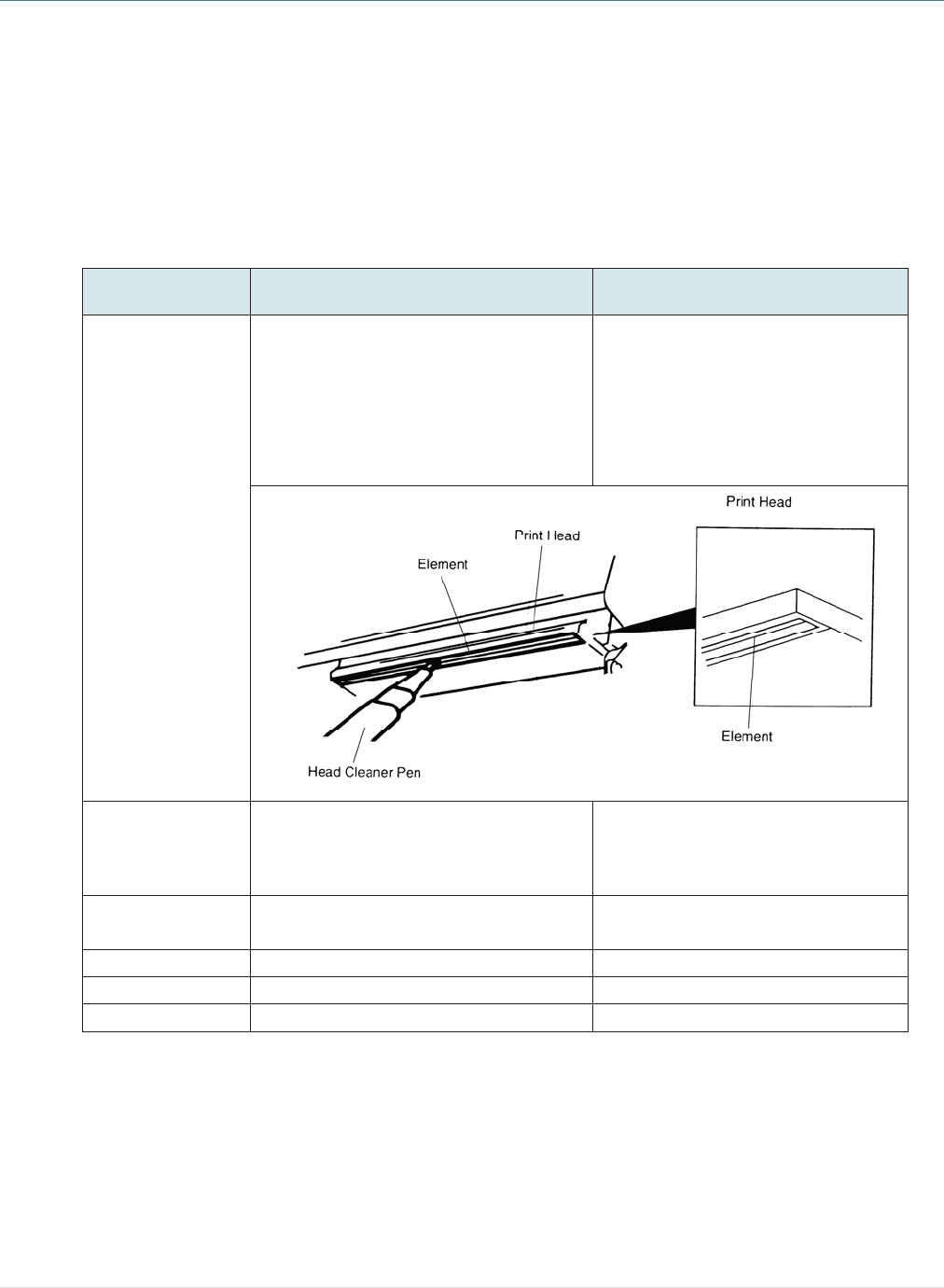
- 59 -
8. Maintenance
This session presents the clean tools and methods to maintain your printer.
1. Please use one of following material to clean the printer.
Cotton swab
Lint-free cloth
Vacuum / Blower brush
100% Ethanol or Isopropyl Alcohol
2. The cleaning process is described as following,
Printer Part Method Interval
Print Head
1. Always turn off the printer before
cleaning the print head.
2. Allow the print head to cool for a
minimum of one minute.
3. Use a cotton swab and 100% Ethanol
or Isopropyl Alcohol to clean the print
head surface.
Clean the print head when changing
a new label roll.
Platen Roller
1. Turn the power off.
2. Rotate the platen roller and wipe it
thoroughly with water.
Clean the platen roller when
changing a new label roll
Peel Bar Use the lint-free cloth with 100% ethanol
to wipe it. As needed
Sensor Compressed air or vacuum Monthly
Exterior Wipe it with water-dampened cloth As needed
Interior Brush or vacuum As needed
Note:
z Do not touch printer head by hand. If you touch it careless, please use ethanol to clean it.
z Please use 100% Ethenol or Isopropyl Alcohol. DO NOT use medical alcohol, which may damage
the printer head.
z Regularly clean the print head and supply sensors once change a new media to keep printer
performance and extend printer life.

- 60 -
Revise History
Date Content Editor
2013/10/4 Modify section 2.3.2 Camille
2013/10/31 Modify section 1.3 and 3.2 Camille
2014/1/8 * Modify section 1.2.2
* Add section 3.6 (Install the adapter for 0.75” and 1” paper core) Camille
2014/1/23 Modify section 1.3 Camille
2014/4/30 Add section 3.7 (Install the belt strap) Camille
2014/5/19 Modify section 1.2.2 Camille
2015/2/10 Update wireless module information Camille

Corporate Headquarters Li Ze Plant
9F., No.95, Minquan Rd., Xindian Dist., No.35, Sec. 2, Ligong 1st Rd., Wujie Township,
New Taipei City 23141, Taiwan (R.O.C.) Yilan County 26841, Taiwan (R.O.C.)
TEL: +886-2-2218-6789 TEL: +886-3-990-6677
FAX: +886-2-2218-5678 FAX: +886-3-990-5577
Web site: www.tscprinters.com
E-mail: printer_sales@tscprinters.com
tech_support@tscprinters.com
TSC Auto ID Technology Co., Ltd.