TSC Auto ID Technology RFWRN WiFi abgn module User Manual Alpha 3R user manual
TSC Auto ID Technology Co., Ltd. WiFi abgn module Alpha 3R user manual
Contents
User Manual

A
l
B
a
lp
ha-
3
a
rcod
3
R S
e
e Pri
n
e
ries
n
ter
i
US
E
MAN
E
R’S
UAL

ii
Copyright Information
©2012 TSC Auto ID Technology Co., Ltd,
The copyright in this manual, the software and firmware in the printer
described therein are owned by TSC Auto ID Technology Co., Ltd, All
rights reserved.
CG Triumvirate is a trademark of Agfa Corporation. CG Triumvirate Bold
Condensed font is under license from the Monotype Corporation. Windows
is a registered trademark of Microsoft Corporation.
All other trademarks are the property of their respective owners.
Information in this document is subject to change without notice and does
not represent a commitment on the part of TSC Auto ID Technology Co.
No part of this manual may be reproduced or transmitted in any form or by
any means, for any purpose other than the purchaser’s personal use,
without the expressed written permission of TSC Auto ID Technology Co.

Ag
e
Wi
c
1.
B
2.
H
3.
V
F
R
4.
D
z
5.
D
6.
B
F
7.
B
8.
D
w
e
ncy Com
p
C
E
E
I
E
E
E
F
C
F
C
F
C
F
C
I
C
I
C
I
C
I
E
A
A
R
E
x
E
c
htige Sich
e
B
itte lesen
S
H
eben Sie
d
V
or jedem
R
F
lüssig-ode
r
R
einigung.
D
ie Netzan
s
z
ugänglich
s
D
as Gerät i
s
B
ei der Auf
s
F
allen könn
t
B
eachten Si
D
ieses Ger
ä
w
erden.
p
liance an
d
E CLASS
B
N 55022:2
0
N 55024:2
0
E
C61000-4
-
N301489-1
N50556:20
C
C CFR Ti
C
C CFR Ti
C
C CFR Ti
C
C 47 CF
R
C
ES-003 Is
s
C
RSS-102
C
RSS-247
E
C 62209-2
A
S/NZS CI
S
A
S/NZS 42
6
R
adio com
m
x
posure)
S
N50566:20
e
rheits-Hin
w
S
ie diese Hi
d
iese Anleit
u
R
einigen ist
r
Aerosolrei
s
chluß-Stec
s
ein.
s
t vor Feuc
h
s
tellung des
t
e Beschäd
e beim An
s
ä
t kann bis
z
d
Approval
s
B
0
10/AC:20
1
0
10 ,IEC61
0
-
5, IEC610
0
,EN30148
9
13,EN6231
t
le 47 Part
t
le 47 Part
t
le 47 Part
R
Part 2(2.1
s
ue 5 Clas
s
Issue 5
Issue 1
(2010),IEE
E
PR22:200
9
8
m
unication
s
S
tandard 2
0
13,EN6231
w
eise
nweis sorg
f
u
ng fűr den
das Gerät
v
niger. Am
b
kdose soll
n
h
tigkeit zu
s
Gerätes is
t
igungen he
s
chluß ans
S
z
u einer Au
iii
s
1
1, EN610
0
0
00-4-2,IE
C
0
0-4-6, IEC
6
9
-17,EN30
0
1
1:2008, E
N
15 Subpa
r
15 Subpa
r
15 Subpa
r
093) ,ANS
/
s
B
E 1528-20
1
9
/A1:2010
C
s (Electro
m
0
14
1
1:2008,EN
f
ältig durch
späteren
G
v
om Strom
e
b
esten eign
n
ahe dem
G
s
chűtzen.
t auf siche
r
rvorrufen.
S
tromnetz
d
ßentempe
r
0
0-3-2:201
4
C
61000-4-
3
6
1000-4-8,
0
328,EN30
1
N
62209-2:2
r
t B Class
B
r
t C
r
t E
/
IEEE C95.
1
3
C
lass B
m
agnetic
R
62209-2:2
0
.
G
ebrauch a
e
ntz zu tre
n
et sich ein
a
G
erät ange
b
r
en Stand z
u
d
ie Anschl
u
r
atur von m
a
4
,EN61000-
, IEC6100
0
IEC61000-
4
893,EN60
9
010, EN62
4
B
1
-1992, IE
E
R
adiation
—
0
10,EN624
7
u
f.
nen. Verw
e
a
ngefeucht
e
b
racht und
l
u
achten. E
ßwerte.
a
ximal 40
℃
-
3-3:2013
0
-4-4,
-
4-11
9
50-1
4
79:2010
E
E 1528-2
0
—
Human
7
9:2010
e
nden Sie
k
etes Tuch
z
l
eicht
E
in Kippen
o
℃
betrieben
0
03
k
eine
z
ur
o
der

iv
Battery safety warning:
DO NOT throw the battery in fire.
DO NOT short circuit the contacts.
DO NOT disassemble the battery.
DO NOT throw the battery in municipal waste.
The symbol of the crossed out wheeled bin indicates that the battery should not be
placed in municipal waste.
ClassB:
FEDERAL COMMUNICATIONS COMMISSION INTERFERENCE STATEMENT
This equipment has been tested and found to comply with the limits for a Class B
digital device, pursuant to part 15 of the FCC Rules. These limits are designed to
provide reasonable protection against harmful interference in a residential installation.
This equipment generates, uses and can radiate radio frequency energy and, if not
installed and used in accordance with the instructions, may cause harmful
interference to radio communications. However, there is no guarantee that
interference will not occur in a particular installation. If this equipment does cause
harmful interference to radio or television reception, which can be determined by
turning the equipment off and on, the user is encouraged to try to correct the
interference by one or more of the following measures:
-Reorient or relocate the receiving antenna.
-Increase the separation between the equipment and receiver.
-Connect the equipment into an outlet on a circuit different from that to which the
receiver is connected.
-Consult the dealer or an experienced radio/ TV technician for help.
CAUTION:
Any changes or modifications not expressly approved by the grantee of this device
could void the user's authority to operate the equipment.
This device complies with Part 15 of the FCC Rules. Operation is subject to the
following two conditions: (1) This device may not cause harmful interference, and (2)
this device must accept any interference received, including interference that may
cause undesired operation.
v
IMPORTANT NOTE:
Federal Communication Commission (FCC) Radiation Exposure Statement
This EUT is compliance with SAR for general population/uncontrolled exposure limits in
ANSI/IEEE C95.1-1999 and had been tested in accordance with the measurement methods
and procedures specified in OET Bulletin 65 Supplement C. This equipment should be
installed and operated contact with the radiator & your body.
For body worn operation, this device has been tested and meets the FCC RF exposure
guidelines when used with the belt clip accessory provided by TSC. Use of other accessories
may not ensure compliance with FCC RF exposure guidelines.
This device complies with Industry Canada's licence-exempt RSSs. Operation is subject to the
following two conditions:
(1) This device may not cause interference; and
(2) This device must accept any interference, including interference that may cause undesired
operation of the device.
Le présent appareil est conforme aux CNR d'Industrie Canada applicables aux appareils radio
exempts de licence. L'exploitation est autorisée aux deux conditions suivantes : (1) l'appareil
ne doit pas produire de brouillage, et (2) l'utilisateur de l'appareil doit accepter tout brouillage
radioélectrique subi, même si le brouillage est susceptible d'en compromettre le
fonctionnement.
High Power Radars: High power radars are allocated as primary users (meaning they have
priority) in the 5250MHz to 5350MHz and 5650MHz to 5850MHz bands. These radars could
cause interference and/or damage to Wireless LAN devices used in Canada.
Les utilisateurs de radars de haute puissance sont désignés utilisateurs principaux (c.-à-d.,
qu'ils ont la priorité) pour les bandes 5250 - 5350 MHz et 5650 - 5850 MHz. Ces radars
pourraient causer du brouillage et/ou des dommages aux dispositifs LAN-EL.
IC Radiation Exposure Statement
This EUT is compliance with SAR for general population/uncontrolled exposure limits in IC
RSS-102 and had been tested in accordance with the measurement methods and procedures
specified in IEEE 1528.
RFexposurewarning(WiFi)
This equipment must be installed and operated in accordance with provided
instructions and must not be co-located or operating in conjunction with any other
antenna or transmitter. End-users and installers must be providing with antenna
installation instructions and transmitter operating conditions for satisfying RF
exposure compliance.
vi
SAR Value: 0.023 W/kg
Canada, Industry Canada (IC) Notices
This Class B digital apparatus complies with Canadian ICES-003 and RSS-247.
Operationissubjecttothefollowingtwoconditions:(1)thisdevicemaynotcause
interference,and(2)thisdevicemustacceptanyinterference,includinginterference
thatmaycauseundesiredoperationofthedevice.
Radio Frequency (RF) Exposure Information
The radiated output power of the Wireless Device is below the Industry Canada
(IC) radio frequency exposure limits. The Wireless Device should be used in such
a manner such that the potential for human contact during normal operation is
minimized.
ThisdevicehasbeenevaluatedforandshowncompliantwiththeICSpecificAbsorption
Rate(“SAR”)limitswheninstalledinspecifichostproductsoperatedinportable
exposureconditions.(ForWiFi)
Canada, avis de l'Industry Canada (IC)
Cet appareil numérique de classe B est conforme aux normes canadiennes ICES-003
et RSS-247.
Son fonctionnement est soumis aux deux conditions suivantes : (1) cet appareil ne
doit pas causer d'interférence et (2) cet appareil doit accepter toute interférence,
notamment les interférences qui peuvent affecter son fonctionnement.
Informations concernant l'exposition aux fréquences radio (RF)
La puissance de sortie émise par l’appareil sans fil est inférieure à la limite
d'exposition aux fréquences radio de l'Industry Canada (IC). Utilisez l’appareil
sans fil de façon à minimiser les contacts humains lors du fonctionnement normal.
CepériphériqueaétéévaluéetdémontréconformeauxlimitesSAR(SpecificAbsorption
Rate–Tauxd'absorptionspécifique)parl'IClorsqu'ilestconnectéàdesdispositifshôtes
spécifiquesopérantdansdesconditionsd’utilisationmobile.(PourleWi‐Fi)
vii
NCC 警語:
經型式認證合格之低功率射頻電機,非經許可,公司、商號或使用者均不得擅自變更頻率、加大
功率或變更原設計之特性及功能。(即低功率電波輻射性電機管理辦法第十二條)
低功率射頻電機之使用不得影響飛航安全及干擾合法通信;經發現有干擾現象時,應立即停用,
並改善至無干擾時方得繼續使用。
前項合法通信,指依電信法規定作業之無線電通信。低功率射頻電機須忍受合法通信或工業、科
學及醫療用電波輻射性電機設備之干擾。(即低功率電波輻射性電機管理辦法第十四條)
viii
Contents
1.Introduction ................................................. 1
1.1 Product Introduction ........................................................................................... 1
1.2 Product Features ................................................................................................. 2
1.2.1 Printer Standard Features ....................................................................... 2
1.2.2 Printer Optional Features ........................................................................ 3
1.3 General Specifications ........................................................................................ 3
1.4 Print Specifications ............................................................................................. 4
1.5 Media Specifications ........................................................................................... 4
2.Operations Overview .......................................... 5
2.1 Unpacking and Inspection .................................................................................. 5
2.2 Printer Overview .................................................................................................. 6
2.2.1 Front View ................................................................................................. 6
2.2.2 Interior View .............................................................................................. 7
2.2.3 Rear View .................................................................................................. 8
2.3 Operator control ................................................................................................... 9
2.3.1 LED Indication and Keys ......................................................................... 9
2.3.1 LED Indication and Keys ....................................................................... 10
3.Setup ..................................................... 11
3.1 Install the Battery ............................................................................................... 11
3.2 Charge the Battery ............................................................................................. 12
3.2.1 Charge the Battery ................................................................................. 12
3.2.2 Charge by Charger Station (Optional) .................................................. 13
3.2.3 Charge by Vehicle Power Adaptor (Optional) ...................................... 14
3.3 Communicate ..................................................................................................... 15
3.3.1 Connecting with the Communication Cable ........................................ 15
3.4 Loading the Media ........................................................................................... 166
Loading the Media ............................................................................................ 16
4.Accessories ................................................ 18
4.1Install the Belt Clip ............................................................................................ 18
4.2 Install the IP54-rated environmental case with shoulder strap (Optional) ... 19
5.Power-on Utilities ........................................... 20
5.1Media Sensor Calibration ................................................................................. 20
5.2Self-test and Dump Mode ................................................................................. 21
5.3Printer Initialization ........................................................................................... 24
6.Diagnostic Tool ............................................. 25
ix
6.1Start the Diagnostic Tool .................................................................................. 25
6.2Printer Function ................................................................................................. 26
6.3Calibrating Media Sensor by Diagnostic Tool ................................................ 27
6.3.1 Auto Calibration ..................................................................................... 27
6.4Setting Wi-Fi by Diagnostic Tool (Optional) ................................................... 28
7.Troubleshooting ............................................ 29
7.1 Common Problems ............................................................................................ 29
8.Maintenance ............................................... 31
Revise History ................................................ 32
1. Introduction
1.1 Product Introduction
Thank you very much for purchasing TSC bar code printer.
Enjoy TSC’s reputation for cost-efficient, high durability printers with the Alpha-3R
economical printer. The Alpha-3R is a comfortable, light-weight printer capable of
working with any mobile printing application where you need quick, simple
receipts/labels on demand.
Our Alpha-3R is designed for a rough life, inside the IP54-rated protective case to
resist dust and water and with its rubber over-mold design prepared to take up to a five
foot fall and keep printing.
These small and light printers can be worn comfortably for a full shift, without interfering
with the user’s tasks. Use USB, 802.11a/b/g/n Wireless or Serial to connect to a
mobile computer or even a smart phone and produce clear easy-to-read receipts hour
after hour.
This document provides an easy reference for operating the Alpha-3R.
The online version of the Programmer's manual, or more information can be
downloaded from service and support web site as an Adobe Acrobat Reader file.
To print label formats, please refer to the instructions provided with your labeling
software; if you need to write the custom programs, please refer to the TSPL/TSPL2
programming manual that can be found on the accessories CD-ROM or on TSC
website at http://www.tscprinters.com.
− Applications
Direct store deliveries (DSD)
Field repair/installation
Mobile point of sale
Parking citations
Mobile ticketing
Onboard transportation ticketing
Utility billing/meter reading

2
1.2 Product Features
1.2.1 Printer Standard Features
The printer offers the following standard features.
Product standard feature
Direct thermal printing
Black mark reflective sensor
Head open sensor
3 operation buttons (On/off, feed, and cover-open)
2 color LED for printer status, 3 LEDs for battery status
USB 2.0 (full speed) interface
8 MB SDRAM memory
4 MB FLASH memory
Powerful 32 bit 200 MHz RISC processor
Eltron® and Zebra® emulation languages support
Internal 8 alpha-numeric bitmap fonts
Fonts and bar codes can be printed in any one of the four directions (0,
90,180, 270 degree)
Internal Monotype Imaging® true type font engine with one CG Triumvirate
Bold Condensed scalable font
Downloadable fonts from PC to printer memory
Downloadable firmware upgrades
Text, bar code, graphics/image printing (Please refer to the TSPL/TSPL2
programming manual for supporting code page)
Supported bar code Supported image
1D bar code 2D bar code
BITMAP,
BMP,
PCX
(Max. 256 colors
graphics)
Code 39,
Code 93,
Code128UCC,
Code128 subsets
A,B,C, Codabar,
Interleaved 2 of 5,
EAN-8, EAN-13,
EAN-128,
UPC-A, UPC-E,
EAN and UPC 2(5)
digits add-on, MSI,
PLESSEY,
POSTNET,
China POST,
GS1 DataBar,
PDF-417,
Maxicode,
DataMatrix,
QR code,
Aztec,

3
1.2.2 Printer Optional Features
The printer offers the following optional features.
Product option feature User
options
Factory
options
802.11 a/b/g/n wireless ○
CPCL emulation
○
Black mark sensor position
(left / right / center) ○
Charge station 1 cell
(with changeable power connector) ○
Vehicle power adapter ○
IP54-rated environmental case with shoulder
strap ○
USB to RS-232 cable ○
USB cable ○
Li-ion battery ○
1.3 General Specifications
General Specifications
Physical dimensions 116 mm (W) x 148 mm (H) x 70 mm (D)
Enclosure Plastic enclosure with rubber over-mold construction
Weight 550 g (1.21 lb)
Electrical DC 7.4V/ 2500 mA/ h rechargeable battery
Environmental
condition
Operation: -10 ~ 50°C (14 ~ 122°F), 10 ~ 90% non-condensing
Storage: -40 ~ 60 °C (-40 ~ 140°F), 10 ~ 90% non-condensing

4
1.4 Print Specifications
Print Specifications Alpha-3R
Print head resolution 203 dots/inch (8 dots/mm)
Printing method Direct thermal
Dot size 0.125 x 0.125 mm
(width x length) (1 mm = 8 dots)
Print speed 2, 3, 4 ips selectable
(inches per second) Up to 4 ips
Max. print width 72 mm (2.83”)
Max. print length 2286 mm (90”)
Printout bias Vertical: 1 mm max.
Horizontal: 1 mm max.
1.5 Media Specifications
Media Specifications Alpha-3R
Media roll capacity Receipt: 57 mm (2.25”) OD
Label: 55 mm (2.16”) OD
Media type
Receipt paper,
Bline receipt paper
(Black mark in printing side) &
Selected label
Media wound type Printing face outside wound
Media width Receipt: 2” ~ 3.15”
Label: 2” ~ 3.07”
Media thickness
Receipt: 0.0508 ~ 0.1016 mm (2 ~ 4 mil)
Label: Fasson standard label media up to
0.14 mm (5.5 mil)
Media height Label: Min. 25.4 mm (1”)
Media core diameter 10.2 ~ 25.4 mm (0.4“ ~ 1“)
5
2. Operations Overview
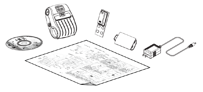
2.1 Unpacking and Inspection
This printer has been specially packaged to withstand damage during shipping. Please
carefully inspect the packaging and printer upon receiving the bar code printer. Please
retain the packaging materials in case you need to reship the printer.
Unpacking the printer, the following items are included in the carton.
One printer unit
One Li-ion battery
One Windows labeling software/Windows driver CD disk
One quick installation guide
One power adaptor
One belt clip
If any parts are missing, please contact the Customer Service Department of your
purchased reseller or distributor.
2.2 Pr
i
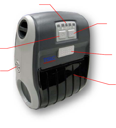
2.2.1 F
r
i
nter O
v
r
ont Vie
w
1. LE
D
2. Fe
e
3. Po
w
4. M
e
5. M
e
6. M
e
v
erview
w
D
indicato
r
e
d button
w
er on/off
e
dia cover
r
e
dia holder
e
dia cove
r
3
5
r
button
r
elease bu
adjustme
n
1
6
u
tton
n
t knob
2
4
6
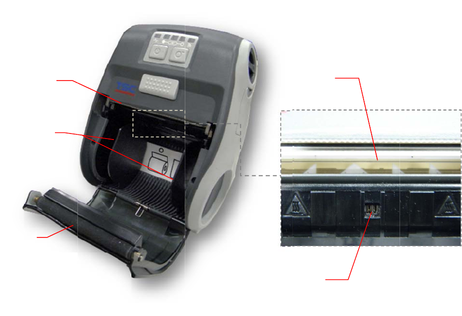
2.2.2 In
4
terior Vi
1. Te
a
2. Pri
n
3. M
e
4. Pl
a
5. Bl
a
1
3
ew
a
r edge
n
t head
e
dia holde
r
a
ten
a
ck mark s
e
e
nso
r
7
2
5
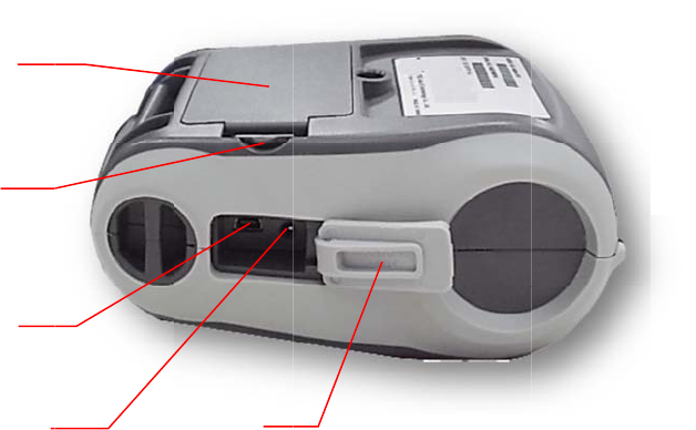
2.2.3 R
e
e
ar Vie
w
1. Li-i
2. Ba
t
3. US
4. Po
w
5. Int
e
3
2
4
1
w
on battery
t
tery open
B interfac
e
w
er jack
e
rface cov
e
clasp
e
er
5
8
9
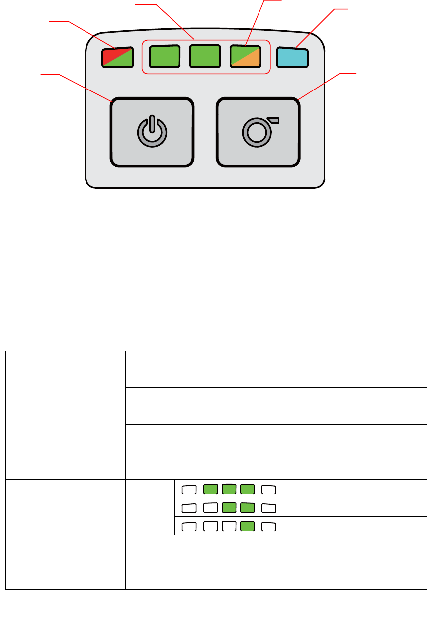
2.3 Operator control
2.3.1 LED Indication and Keys
1. Power on/off button
2. Printer status LED indicator
3. Battery charge level LED indicator
4. Battery status LED indicator
5. Wireless status LED indicator
6. Feed button
LED Status Indication
Printer status LED
indicator
Off Printer is ready
Green (blinking) Printer is paused
Red (solid) Media cover is open
Red (blinking) Printer error
Battery status LED
indicator
Green (blinking) Recharge the battery
Amber (solid) Battery is charging
Battery charge level
LED indicator
Green
(solid)
Full charged
2/3 charged level
1/3 charged level
Wireless status LED
indicator
Blue (solid) Wireless device is ready
Blue (blinking) Wireless device is
communicating
2
3 4 5
1 6
Note: Wireless module is optional for Alpha-3R model.

10
Keys Function
1. Press and hold for 2-3 seconds to turn on the printer.
2. Press and hold for 2-3 seconds to turn off the printer.
1. Ready status: Feed one label
2. Printing status: Pause the print job
3. S
e
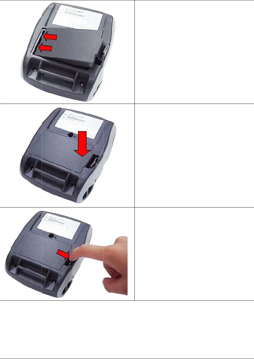
3.1 In
s
B
D
D
T
p
e
tup
s
tall th
e
B
attery safe
t
D
O NOT thr
o
D
O NOT dis
a
T
he symbol
p
laced in m
u
e
Batter
y
t
y warning:
o
w the batt
e
a
ssemble t
h
of the cr
o
u
nicipal wa
s
y
e
ry in fire. D
h
e battery.
D
ssed out
w
s
te.
PUSH
11
O NOT sho
r
D
O NOT thr
o
w
heeled bin
1. Inser
t
batte
r
2. Push
3. Pull t
h
batte
r
r
t circuit th
e
o
w the batt
e
indicates
t
the left si
d
r
y at the re
the right s
h
e battery
c
r
y.
e
contacts.
e
ry in muni
c
t
hat the ba
t
d
e to insta
e
ar of the
p
ide of the
b
clasp to lo
c
ipal waste.
a
ttery shoul
ll the
p
rinte
r
.
b
attery.
ck the
d
not be
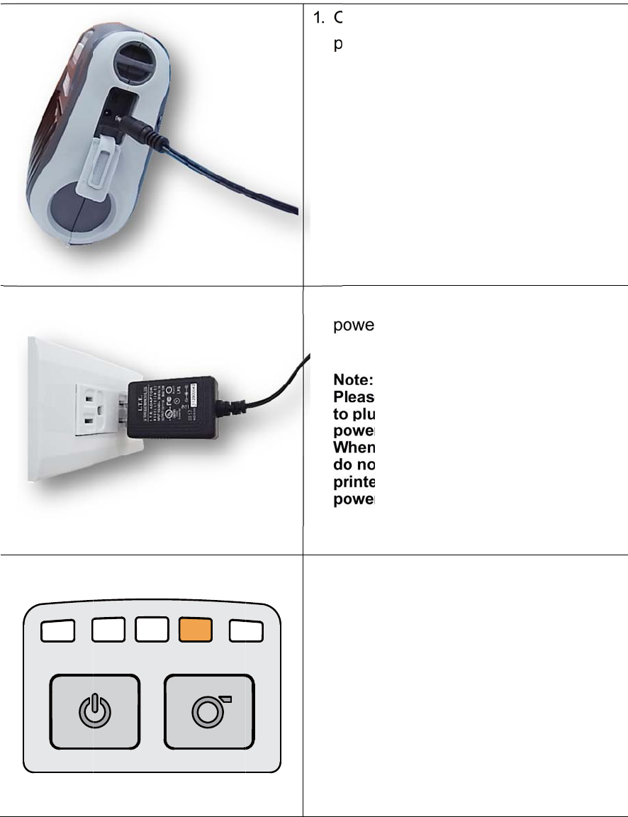
3.2 C
h
It t
a
of t
h
3.2.1 C
h
h
arge th
a
kes 2 to 3
h
e battery
h
arge th
e Batte
hours to
f
is 300 tim
e
e Batter
y
ry
f
ully charg
e
e
s for cha
r
y
12
e
the batt
e
r
ge/discha
1
2
3
ry before
t
rge cycles
. Open th
e
power c
o
. Plug the
power o
u
Note:
Please s
w
to plug i
n
power ja
c
When th
e
do not r
e
printer,
o
power c
o
. When th
e
color of
b
solid am
b
Note:
When ch
battery i
s
amber o
f
t
he first ti
m
.
e
interface
o
rd to the
p
power cor
u
tlet.
w
itch OFF
n
the powe
c
k.
e
battery i
s
e
move the
b
o
therwise,
p
o
rd into a
p
e
battery i
s
b
attery sta
t
b
er.
a
rging ov
e
s
complete
f
LED indic
m
e usage.
T
cover an
d
p
ower jac
k
r
d into a p
r
printer po
w
e
r cord to
p
s
charging,
b
attery fro
p
lease re-
p
p
ower outl
e
s
charging
t
us LED in
e
r 4 ~ 8 hrs
e
ly charge
d
c
ator will b
e
T
he lifetim
e
d
plug the
.
r
operly
w
er prior
p
rinter
please
m
the
p
lug the
e
t.
, the
dicator is
, the
d
and the
e
off.
e
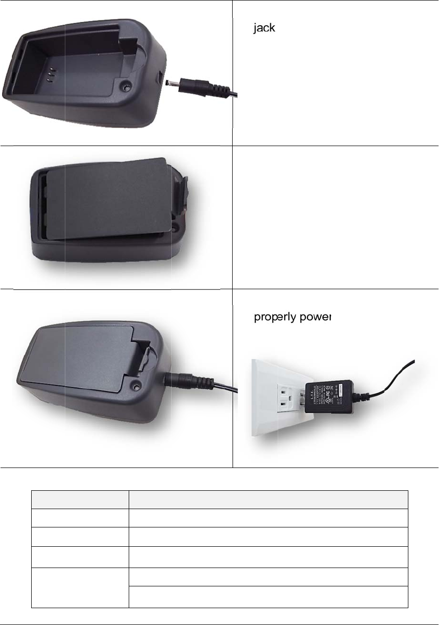
3.2.2 C
h
h
arge b
y
L
E
Gre
R
e
Red
y
Charg
e
E
D Colo
r
en / Solid
e
d / Solid
/ Blinking
Off
e
r Statio
n
Batter
y
Batter
y
Batter
y
No bat
t
Batter
y
13
n
(Optio
n
y
is compl
e
y
is chargi
n
y
charging
tery
y
is compl
e
n
al)
1. Plug
j
ack
2. Inst
a
stati
o
3.1)
3. Plug
prop
e
Descri
p
e
tely char
g
n
g
erro
r
e
tely char
g
the powe
r
o
n the ch
a
a
ll the batt
e
o
n. (Refer
t
the powe
r
e
rly powe
r
tion
ed
ed over 4
r
cord to t
h
a
rger stati
o
e
ry in the
c
to steps o
n
r
co
r
d into
r
outlet.
~ 8 hrs.
h
e power
o
n.
c
harger
n
section
a
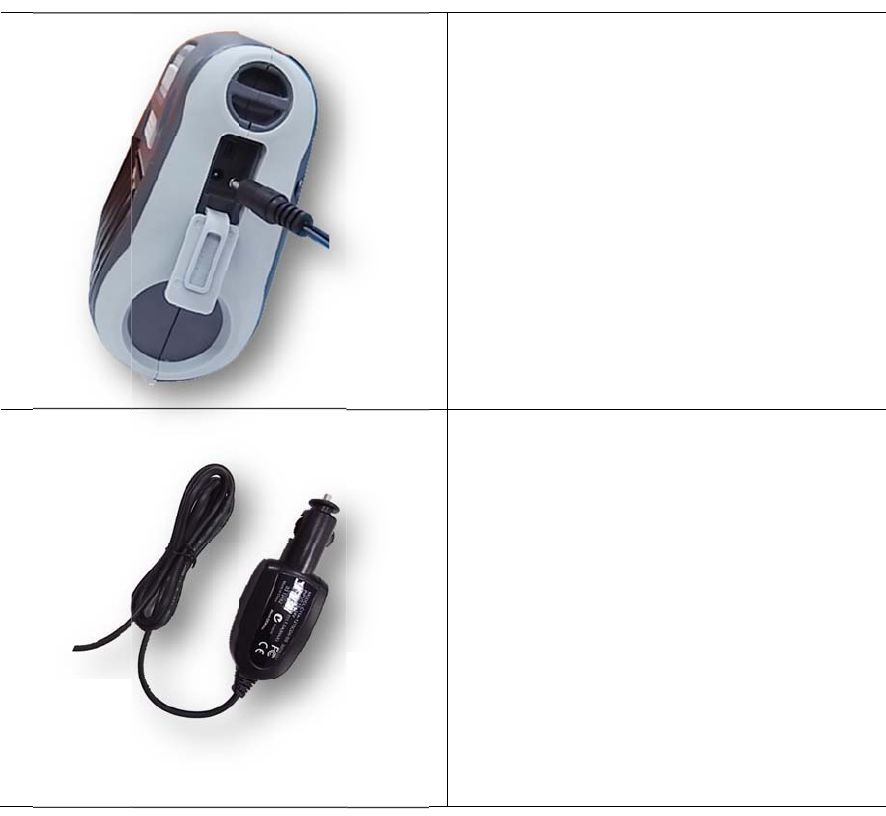
3.2.3 C
h
h
arge b
y
y
V
ehicl
e
e
Power
A
14
A
daptor
(Option
a
1. Ope
n
the p
o
2. Plug
t
into t
h
a
l)
n
the interf
a
o
wer cord
t
he vehicl
e
h
e car cig
a
a
ce cover
to the po
w
e
power a
d
a
rette light
e
and plug
w
er jack.
d
aptor
e
r socket.
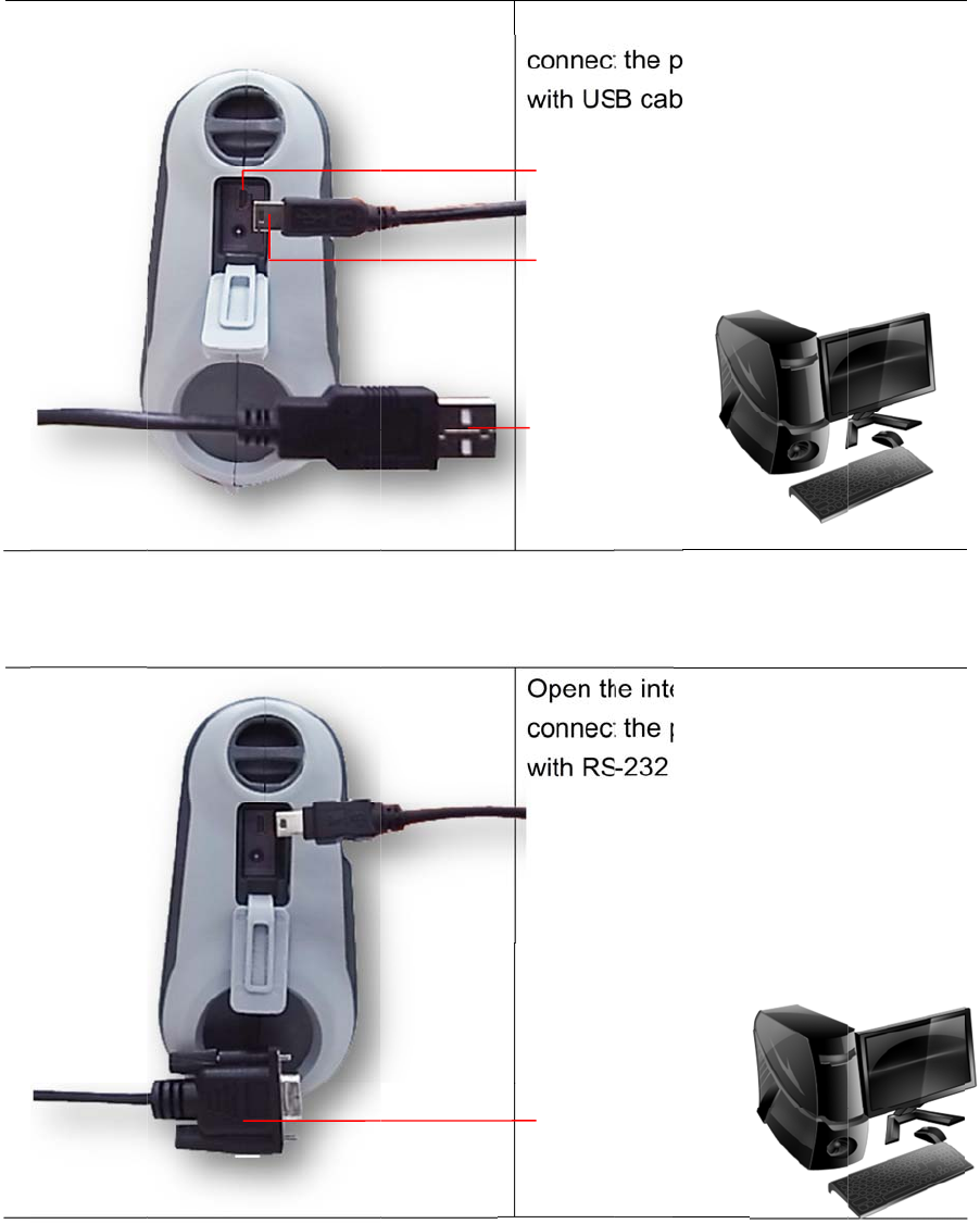
3.3 C
o
3.3.1 C
o
*
U
*
U
o
mmuni
o
nnecti
n
U
SB to U
S
U
SB to R
S
cate
n
g with t
h
S
B Cable (
O
S
-232 Cabl
e
h
e Com
m
O
ptional)
e
(Option
a
15
m
unicati
a
l)
on Cabl
e
Open t
h
connec
t
with U
S
Open t
h
connec
t
with R
S
USB
c
(Print
e
USB c
o
(PC)
USB i
n
RS-2
3
(PC)
e
h
e interfac
e
t
the print
e
B cable.
h
e interfac
e
t
the print
e
-232 cabl
e
onnector
e
r)
o
nnector
n
terface
3
2 connect
o
e
cover an
e
r to the c
o
e
cover an
e
r to the c
o
e
.
o
r
d
o
mputer
d
o
mputer
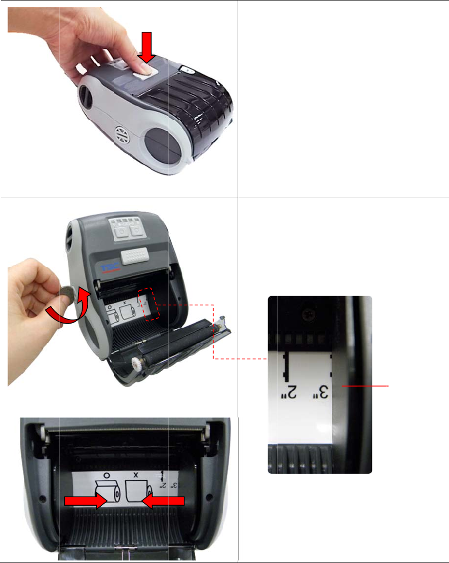
3.4
L
L
oadin
g
g
the M
e
e
dia
16
1. O
p
r
r
e
2. U
s
h
o
m
a
t
m
Note:
The
m
overl
a
medi
a
visib
l
pen the pr
r
essing th
e
e
lease butt
o
s
e a coin t
o
o
lder adju
s
edia hold
e
the corre
c
edia roll.
m
edia holde
a
p the bold
a
holder ali
g
e.
r
inter medi
a
e
media c
o
on.
t
o rotate th
s
tment kn
o
er
should
b
c
t place to
e
r should b
e
line and re
m
g
nment ind
i
a
cover b
y
ver
e media
o
b, and th
e
b
e placed
fit the
e
positioned
m
ain the
cator
Media h
o
y
e
o
lde
r
17
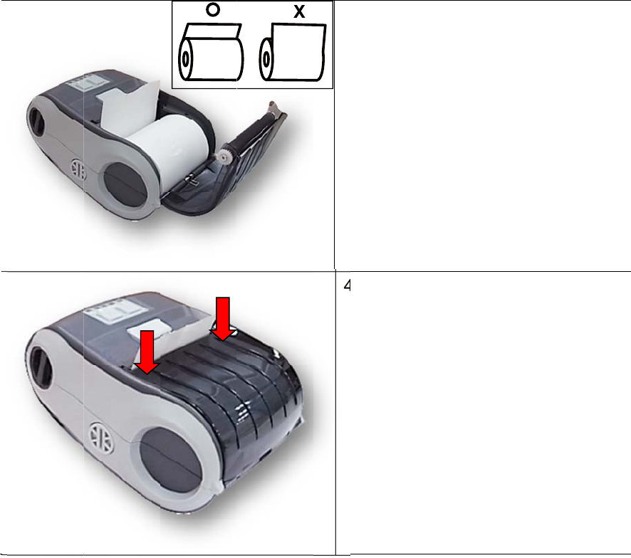
3. P
l
c
o
p
a
4. P
r
t
o
m
cl
o
ace the m
o
rrect side
,
a
per over
t
r
ess each
s
close the
ake sure t
h
o
sed corr
e
edia roll a
t
,
and pull
o
t
he tear e
d
side of m
e
media co
v
he media
c
e
ctly.
t
the
o
ut enoug
h
d
ge.
e
dia cover
v
er and
c
over
h
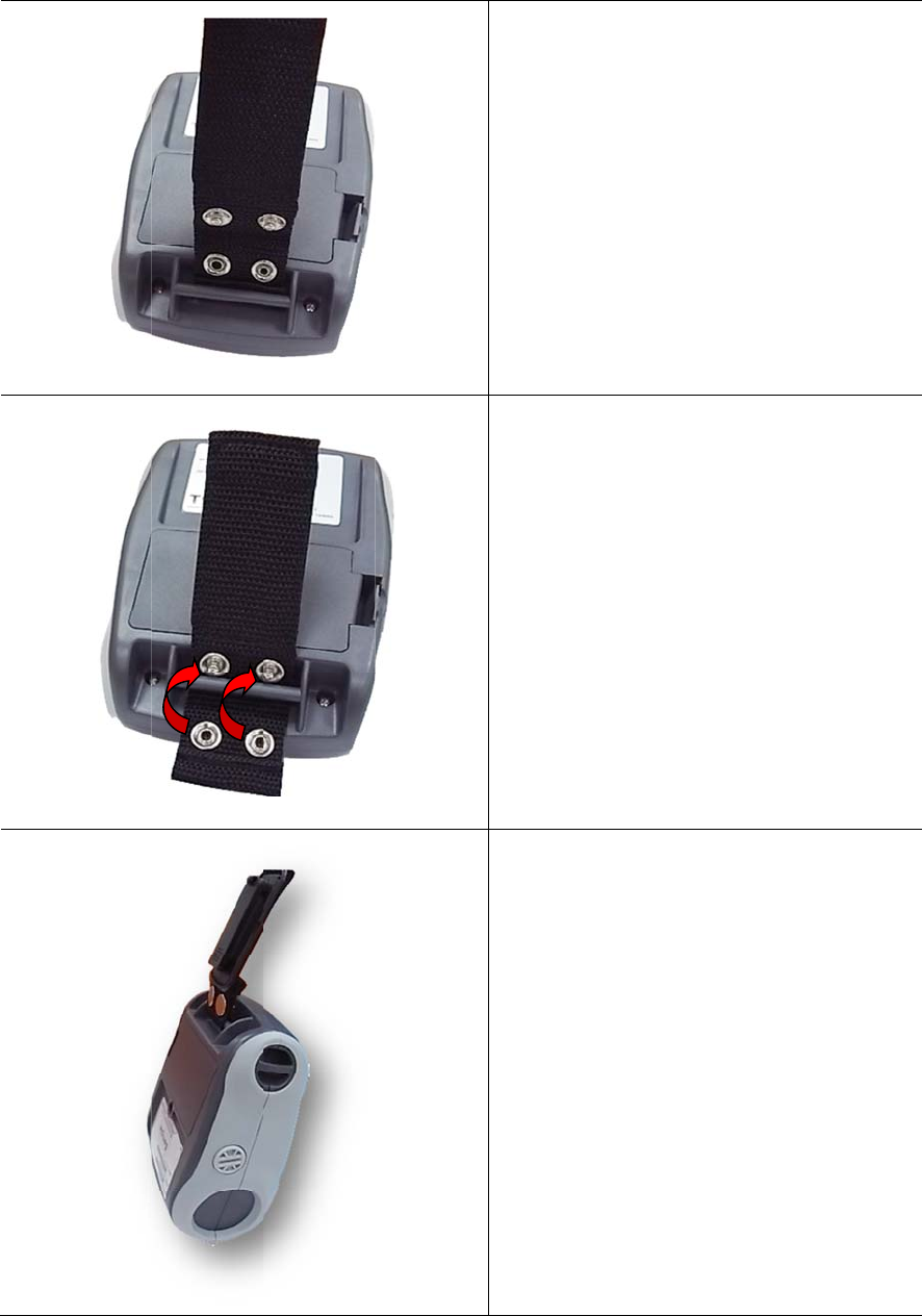
4. A
c
4.1 In
s
c
cess
o
s
tall the
o
ries
Belt C
l
l
ip
18
1. Ref
e
belt
c
the
b
2. Fast
butt
o
3. The
belt.
e
r to figure
c
lip throug
b
attery.
e
n the bel
t
o
ns.
printer ca
n
beside. L
o
h the slot
b
t
clip with
2
n
be hung
o
op the
b
elow
2
o
n the
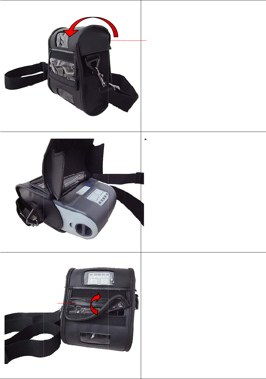
4.2 In
s
(O
s
tall the
ptional
)
Outside c
o
IP54-r
a
)
o
ve
r
a
ted en
v
19
v
ironm
e
e
ntal c
a
1. Ope
n
2. Put
t
3. Clos
the
o
ope
n
Top co
v
a
se wit
h
n
the case
t
he printer
e the cas
e
o
utside co
v
n
ed while
p
v
e
r
h
shoul
d
e
top cover
into the c
a
e
top cove
r
v
er should
p
rinting.
d
er stra
.
a
se.
r
. And
be
p
20
5. Power-on Utilities
There are three power-on utilities to set up and test printer hardware. These utilities are
activated by pressing FEED button( ) then turning on the printer power simultaneously
and release the button at different positions of LED indicator.
Please follow the steps below for different power-on utilities.
1. Turn off the printer power switch.
2. Hold on the FEED button( ) then turn on the power switch.
3. Release the button( ) when LED indicates with different positions for different
functions.
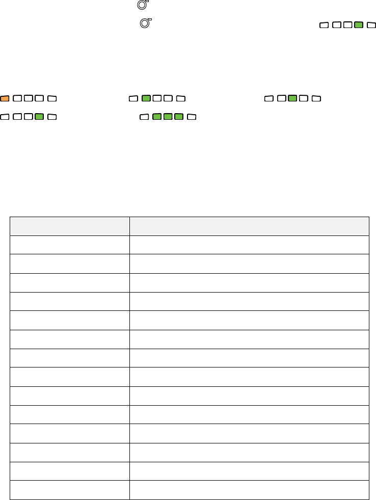
Power on utilities The positions of LED light will be changed as following pattern:
LED
Functions (Solid) (5 blinks) (5 blinks)
(5 blinks) (Solid green)
1. Media sensor calibration Release
2. Self-test and enter dump
mode
Release
3. Printer initialization Release
5.1 Media Sensor Calibration
Please follow the steps below to calibrate the media sensor.
1. Turn off the power switch.
2. Hold on the FEED button( ) then turn on the power switch.
3. Release the FEED button( ) when the indicator becomes and
blinking. (Any green will do during the 5 blinks)
It will calibrate the black mark sensor sensitivity.
The LEDs will be changed as following order:
(amber) (5 blinks) (5 blinks)
(5 blinks) (solid green)

21
5.2 Self-test and Dump Mode
Please follow the steps below.
1. Turn off the power switch.
2. Hold on the FEED button( ) then turn on the power switch.
3. Release the FEED button( ) when the indicator becomes and
blinking. (Any green will do during the 5 blinks)
The LEDs will be changed as following order:
(amber) (5 blinks) (5 blinks)
(5 blinks) (solid green)
4. It calibrates the sensor and measures the media length and prints internal settings
then enter the dump mode.
5. Turn off / on the power to resume printer for normal printing.
22
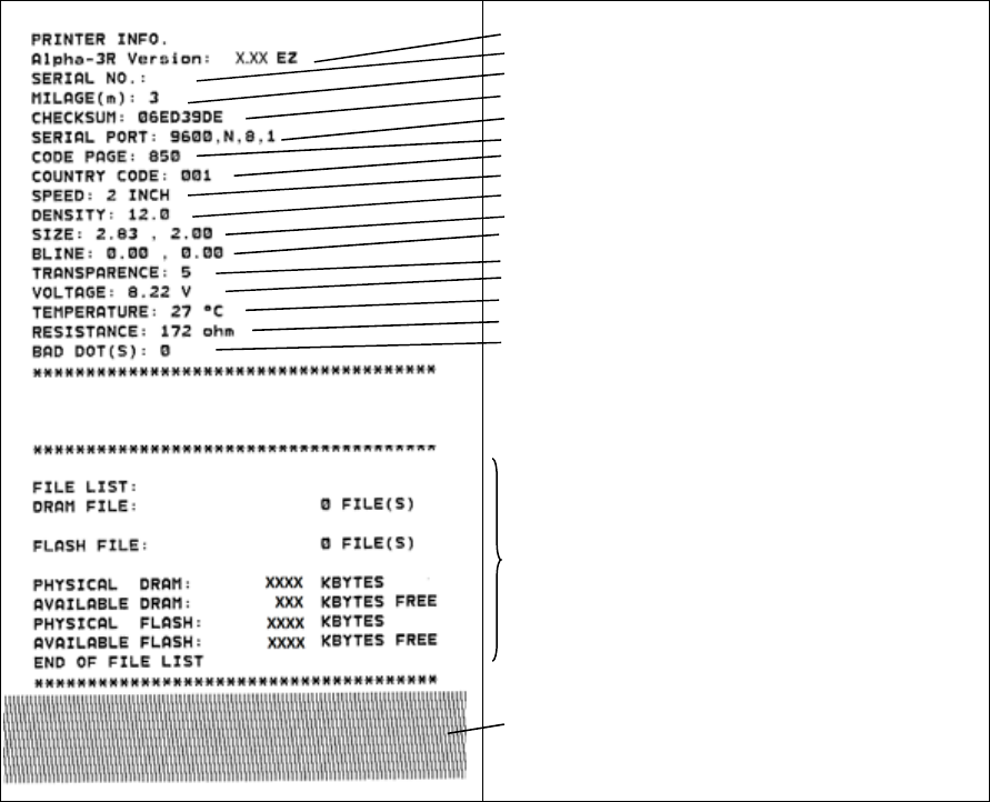
Self-test
Printer will print the printer configuration after media sensor calibration. Self-test
printout can be used to check if there is any dot damage on the heater element,
printer configurations and available memory space.
Printer model name & Main board firmware version
Printer serial number
Printed mileage
Main board firmware checksum
Serial port setting
Code page
Country code
Print speed
Print darkness
Label size (width, height)
Black mark (vertical gap, offset)
Sensor sensitivity
Battery voltage
Print head temperature
Print head average resistance
Bad dots of print head
File management information
Print head test pattern
23
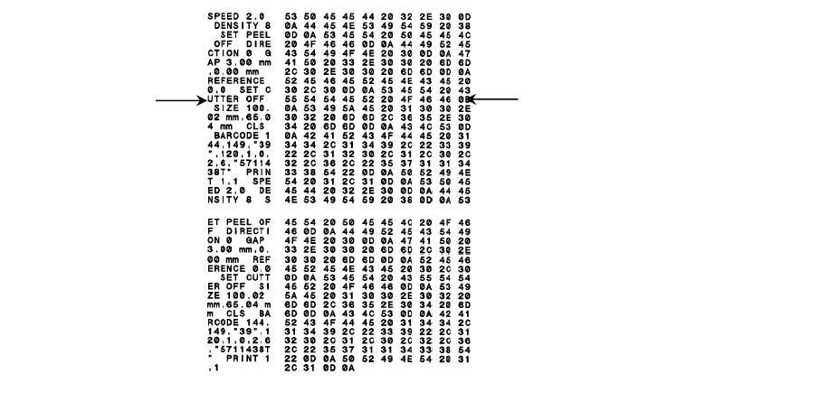
Dump mode
Printer will enter dump mode after printing printer configuration. In the dump mode,
all characters will be printed in 2 columns as following. The left side characters are
received from your system and right side data are the corresponding hexadecimal
value of the characters. It allows users or engineers to verify and debug the
program.
Note:
1. Dump mode requires 3” wide paper width.
2. Turn off / on the power to resume printer for normal printing.
ASCII Data Hex decimal data related to left
column of ASCII data
24
5.3 Printer Initialization
Printer initialization is used to clear DRAM and restore printer settings to defaults.
Printer initialization is activated by the following procedures.
1. Turn off the power switch.
2. Hold on the FEED button( ) then turn on the power switch.
3. Release the FEED button( ) when the indicator becomes and
blinking. (Any green will do during the 5 blinks).
The LEDs will be changed as following:
(amber) (5 blinks) (5 blinks)
(5 blinks) (solid green)
Printer configuration will be restored to defaults as below after initialization.
Parameter Default setting
Speed 50.8 mm/sec (2 ips)
Density 8
Media Width 2.83” (72 mm)
Media Height 4” (101.5 mm)
Sensor Type Black mark sensor (As paper end sensor)
Black Mark Setting As paper end sensor
Print Direction 0
Reference Point 0,0 (upper left corner)
Offset 0
Serial Port Settings 9600 bps, none parity, 8 data bits, 1 stop bit
Code Page 850
Country Code 001
Clear Flash Memory No
IP Address DHCP
25
6. Diagnostic Tool
TSC’s Diagnostic Utility is an integrated tool incorporating features that enable you to
explore a printer’s settings/status; change a printer’s settings; download graphics,
fonts and firmware; create a printer bitmap font; and send additional commands to a
printer. With the aid of this powerful tool, you can review printer status and settings in
an instant, which makes it much easier to troubleshoot problems and other issues.
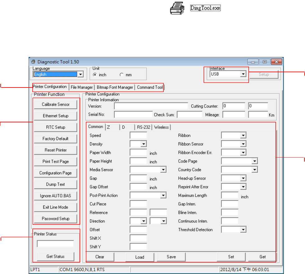
6.1 Start the Diagnostic Tool
1. Double click on the Diagnostic tool icon to start the software.
2. There are four features (Printer Configuration, File Manager, Bitmap Font Manager,
Command Tool) included in the Diagnostic utility.
Features tab
Printer functions
Interface
Printer Status
Printer setup
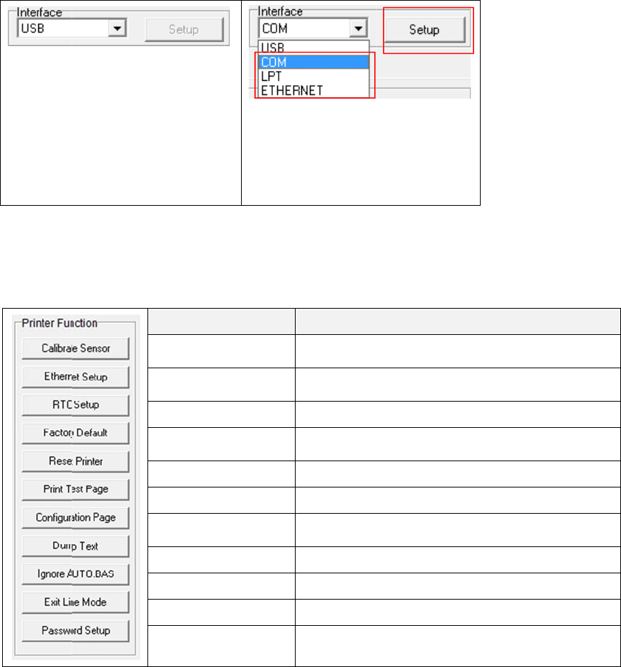
6.2 Pri
1.
2.
3.
F
g
nter F
u
Select the
The defa
u
USB inte
r
is conne
c
other set
t
changed
Click the “
The detail
F
or more in
f
g
uide in the
u
nction
PC interf
a
u
lt interfac
e
r
face. If US
c
ted with pri
t
ings need
t
in the inter
f
Printer Fu
n
functions
f
ormation a
b
CD disk \ U
a
ce conne
c
e
setting is
B
interface
nter, no
t
o be
f
ace field.
n
ction” bu
t
in the Prin
Fun
c
Calibrate
S
Ethernet S
e
RTC Setu
p
Factory De
Reset Prin
t
Print Test
P
Configurati
o
Dump Text
Ignore AU
T
Exit Line M
Password
S
b
out Diagn
o
t
ilities dire
c
26
c
ted with
b
t
ton to set
u
ter Functi
o
c
tion
S
ensor
e
tup
p
e
fault
t
er
P
age
on Page
t
T
O.BAS
M
ode
S
etup
o
stic Tool,
p
c
tory.
b
ar code p
r
u
p.
o
n Group
a
Calibrate th
e
group medi
a
Setup the I
P
the on boar
d
Synchroniz
e
Initialize the
factory defa
Reboot prin
t
Print a test
p
Print printer
5.2)
To activate
t
Ignore the
d
Exit line mo
d
Set the pas
s
p
lease refer
1
r
inte
r
.
a
re listed a
Desc
r
e
sensor sp
e
a
sensor fiel
d
P
address, s
u
d
Etherne
t
e
printer Re
a
printer and
u
lt. (Please
r
t
er
p
age
configuratio
t
he printer d
u
ownloaded
A
d
e.
s
word to pro
t
to the diag
n
2
a
s below.
ription
e
cified in the
d
u
bnet mask,
a
l Time Cloc
k
restore the
s
r
efer section
n (Please re
u
mp mode.
A
UTO.BAS
p
t
ect the setti
n
ostic utilit
y
2
Printer Setu
gateway for
k
with PC
s
ettings to
5.3)
fer section
p
rogram
ngs
y
quick star
t
p
t
27
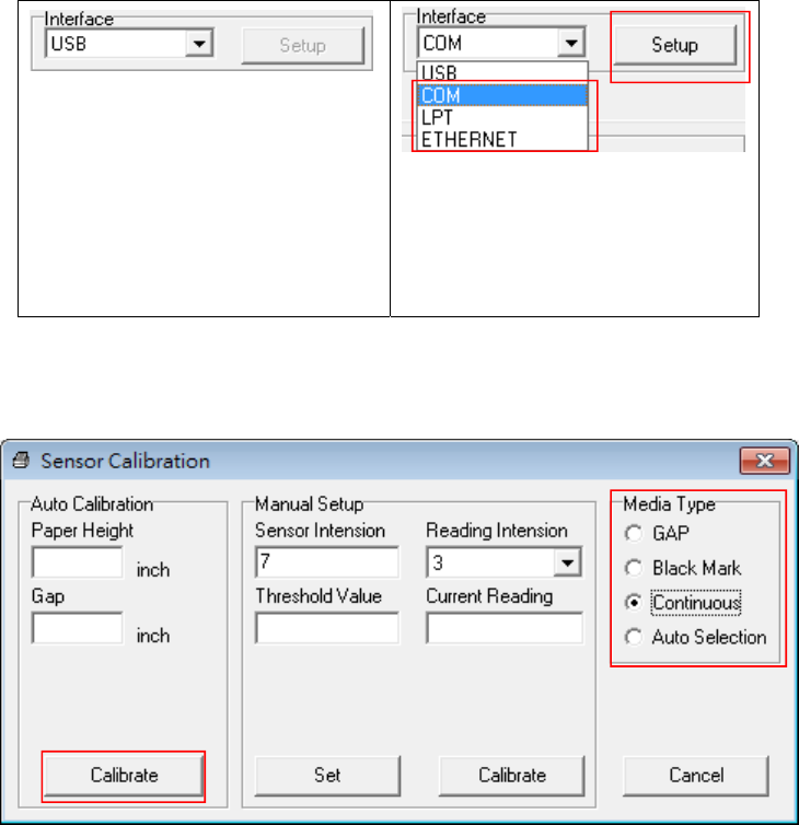
6.3 Calibrating Media Sensor by Diagnostic Tool
6.3.1 Auto Calibration
1. Make sure the media is installed ready and media cover is closed. (Please refer to
section 3.4)
2. Turn on the printer power switch.
3. Open Diagnostic tool and set interface. (The default setting is USB)
The default interface setting is
USB interface. If USB interface
is connected with printer, no
other settings need to be
changed in the interface field.
4. Click the “Calibrate Sensor” button.
5. Select the media type and click the “Calibrate” button.
Note:
The Alpha-3R can only support black mark and continuous of media type.
1
2
1
2
28
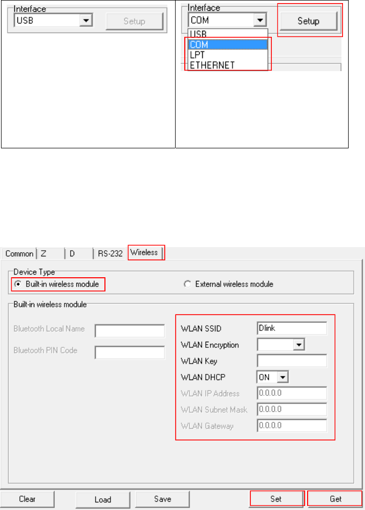
6.4 Setting Wi-Fi by Diagnostic Tool (Optional)
1. Make sure the media is installed ready and media cover is closed. (Please refer to
section 3.4)
2. Turn on the printer power switch.
3. Open Diagnostic tool and set interface. (The default setting is USB)
The default interface setting is
USB interface. If USB interface
is connected with printer, no
other settings need to be
changed in the interface field.
4. Select “Wireless” tab and “Built-in wireless module” item.
5. Enter and select the new WLAN settings in the editor.
6. Press “Set” button to set the new settings to the printer.
7. Press “Get” button to make sure WLAN is set properly.
Note:
* The printer connects with the computer via USB cable or RS-232 cable, which are option.
* Diagnostic tool higher than V1.50 and the firmware higher than V1.22 can support this
function.
1
2
3
4
1
2
5

29
7. Troubleshooting
7.1 Common Problems
The following guide lists the most common problems that may be encountered when operating
this bar code printer. If the printer still does not function after all suggested solutions have been
invoked, please contact the Customer Service Department of your purchased reseller or
distributor for assistance.
Problem Possible Cause Recovery Procedure
Power indicator does not
illuminate
* The battery is not properly
installed.
* The battery is dead.
* Reinstall the battery.
* Switch the printer on.
* Charge the battery.
- The printer status from
DiagTool shows “Head
Open”.
* The printer carriage is open. * Please close the print carriage.
- The printer status from
DiagTool shows “Out of
Paper”..
* Running out of media roll.
* The media is installed
incorrectly.
* Black mark sensor is not
calibrated.
* Supply a new media roll.
* Please refer to the steps on section 3.4 to
reinstall the media roll.
* Calibrate the black mark sensor.
- The printer status from
DiagTool shows “Paper Jam”.
* Black mark sensor is not set
properly.
* Make sure media size is set
properly.
* Media may be stuck inside
the printer mechanism.
* Calibrate the black mark sensor.
* Set media size correctly.
Memory full
( FLASH / DRAM )
* The space of FLASH/DRAM
is full.
* Delete unused files in the FLASH/DRAM.
* The max. numbers of DRAM is 256 files.
* The max. user addressable memory space
of DRAM is 256KB.
* The max. numbers of file of FLASH is 256
files.
* The max. user addressable memory space
of FLASH is 2560KB.
Poor Print Quality
* Media is loaded incorrectly
* Dust or adhesive
accumulation on the print
head.
* Print density is not set
properly.
* Printhead element is
damaged.
* Reload the supply.
* Clean the print head.
* Clean the platen roller.
* Adjust the print density and print speed.
* Run printer self-test and check the print
head test pattern if there is dot missing in
the pattern.
* Change proper media roll.
Missing printing on the left or
right side of label * Wrong label size setup. * Set the correct label size.
Gray line on the blank label * The print head is dirty.
* The platen roller is dirty.
* Clean the print head.
* Clean the platen roller.

30
Irregular printing
* The printer is in Hex Dump
mode.
* The RS-232 setting is
incorrect.
* Turn off and on the printer to skip the
dump mode.
* Re-set the Rs-232 setting.
31
8. Maintenance
This session presents the clean tools and methods to maintain your printer.
1. Please use one of following material to clean the printer.
Cotton swab
Lint-free cloth
Vacuum / Blower brush
100% Ethanol or Isopropyl Alcohol
2. The cleaning process is described as following,
Printer Part Method Interval
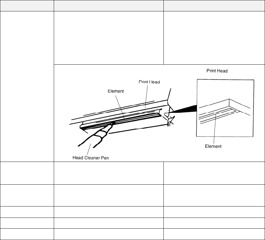
Print Head
1. Always turn off the printer before
cleaning the print head.
2. Allow the print head to cool for a
minimum of one minute.
3. Use a cotton swab and 100%
Ethanol or Isopropyl Alcohol to
clean the print head surface.
Clean the print head when
changing a new label roll
Platen Roller 1. Turn the power off.
2. Rotate the platen roller and wipe it
thoroughly with water.
Clean the platen roller when
changing a new label roll
Tear Bar/Peel
Bar
Use the lint-free cloth with 100%
ethanol to wipe it. As needed
Sensor Compressed air or vacuum Monthly
Exterior Wipe it with water-dampened cloth As needed
Interior Brush or vacuum As needed
Note:
Do not touch printer head by hand. If you touch it careless, please use ethanol to clean
it.
Please use 100% Ethenol or Isopropyl Alcohol. DO NOT use medical alcohol, which
may damage the printer head.
Regularly clean the print head and supply sensors once change a new ribbon to keep
printer performance and extend printer life.

32
Revise History
Date Content Editor
2013/4/3 Add standards for C-Tick Camille
2013/5/14 Modify the section 1.3 Camille
2013/5/24 Modify the section 1.5 Camille
2013/8/26 Update pictures for Alpha-3R Camille
2013/11/12 Modify section 1.1
Modify section 1.5 Camille

Corporate Headquarters Li Ze Plant
9F., No.95, Minquan Rd., Xindian Dist., No.35, Sec. 2, Ligong 1st Rd., Wujie Township,
New Taipei City 23141, Taiwan (R.O.C.) Yilan County 26841, Taiwan (R.O.C.)
TEL: +886-2-2218-6789 TEL: +886-3-990-6677
FAX: +886-2-2218-5678 FAX: +886-3-990-5577
Web site: www.tscprinters.com
E-mail: printer_sales@tscprinters.com
tech_support@tscprinters.com
TSC Auto ID Technology Co., Ltd.