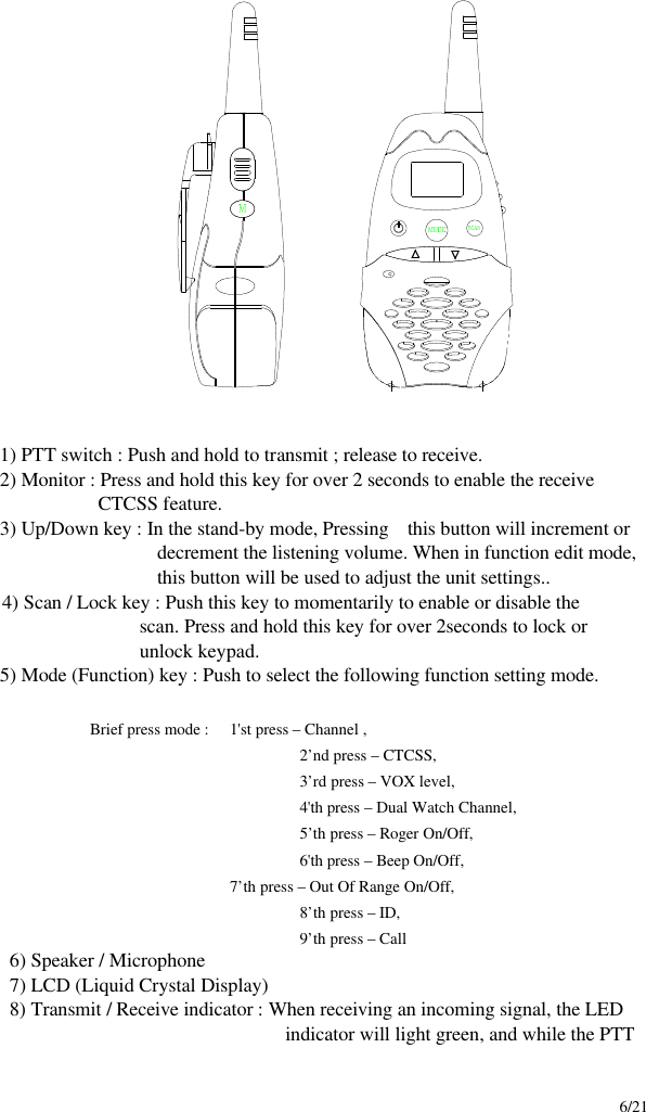
TTI Tech FRS-3000PKH FRS Transceiver User Manual Manual hand
TTI Tech Co., Ltd. FRS Transceiver Manual hand
UserManual.wiki
>
TTI Tech
>
FRS 3000PKH User Manual
User Manual
Navigation menu
Upload a User Manual
Namespaces
Wiki Guide
HTML
PDF
Info
Views
User Manual
Discussion / Help
Navigation
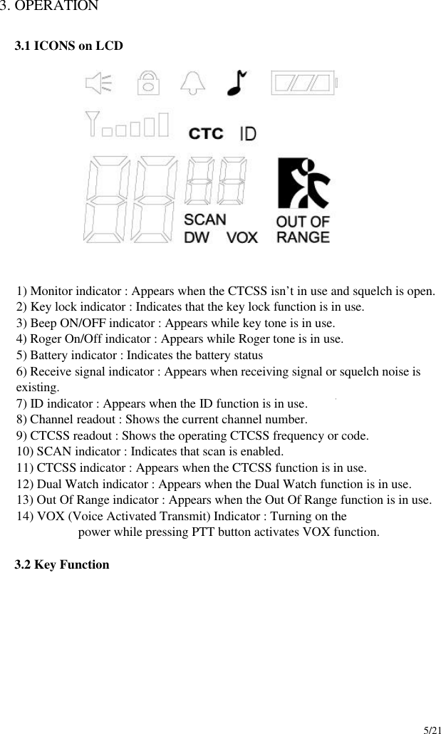
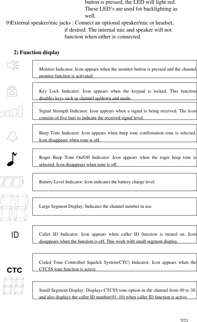
![8/21 3-3. SETTING AND OPERATION In order to communicate with other FRS units, both you and the receiving party must be on the same channel. FRS 3000-PK has 14channels indicated by the large digits on the LCD display panel. Before trying to transmit on the selected channel, you should press the Monitor Button to check the activity on that channel. If someone is already on the selected channel, you should try another channel that is clear 1) On/Off & Volume control Switch Radio ON : Press the power button at least for 2 seconds.You will hear confirming melody to indicated the unit is on. Radio OFF : Press the power button at least for 2 seconds. Volume setting : Press up[ù]or down[ü] button to adjust a level that is most comfortable for you while monitor is active. 2) Setting the Channel and Tone Code(CTCSS) FRS 3000-PK has 14 main channels and 38 sub-channels. * 14 Frequency channels * 38 CTCSS Code ( indicated by CTC icon on the LCD ) 14) Channel readout : Shows the current channel number . Scan Indicator: This function allows users to scan a channel to search for a valid signal. Dual Watch mode Indicator: Icon appears when dual watch mode is active. Voice Activated Transmission (VOX) Indicator: This function allows handsfree conversation. The Icon appears when the VOX mode is activated. Out of Range Alarm Indicator: When this function is active, Icon blinks the receiving signal is getting weaker. The Icon stops blinking when the receiving signal comes back to the normal strength.](https://usermanual.wiki/TTI-Tech/FRS-3000PKH/User-Guide-233447-Page-8.png)
![9/21 To select the channel * Turn the radio on. * Press MODE button once, [XX] digit will blink on the LCD. XX is a channel. * Press up[ù]or down[ü] button to choose the channel. * Press the PTT button or MODE button to confirm. To set the tone codes(CTCSS) * Press MODE button once more, [XX 00 up to 38] will appear and CTC icon and tone code digit will blink on the LCD. “00” means no CTCSS code. * Press up[ù]or down[ü] button to choose the desired sub-channel to use. * Press the PTT button or MODE button to confirm. NOTE : To communicate with other FRS units, they must be switched to the same channel and CTCSS sub-code. To communicate with other GMRS units that do not have sub-codes, switch your unit to the same channel with the sub-code set to OFF. 3) VOX (Voice Operated Switching) This option enables you to have hands-free conversation. You do not have to operate the PTT button each time when you want to transmit. You can also choose the VOX sensitivity so suit your environment of operation. ( Ex : noisy road, motor bike, factory etc. ) To Set the VOX mode * Press the MODE button until the [Uo oF Or XX] appears. XX is a vox level * VOX icon will be appeared on the LCD. To Set the VOX level * Press the up[ù]or down[ü] button to set the VOX level from 1 to 5. “oF” is disable the VOX function. “01” is least sensitive. “05” is most sensitive. * Press the PTT button or MODE button to confirm. 4) Setting the DW (dual watch) To set the DW mode * Press the MODE button until the [ oF of 01 up to 15] and DW icon blink on the LCD. * DW icon will appear on the LCD. To set the dual watch(DW) channel * Press the up[ù]or down[ü] button to choose the channel. “oF” means no DW mode.](https://usermanual.wiki/TTI-Tech/FRS-3000PKH/User-Guide-233447-Page-9.png)
![10/21 “01 up to 15” means the channel that is dual-watched. * Press the PTT button or MODE button to confirm. 5) Roger tone This feature will give the tone signal to other parties when transmitting finished (when PTT button is released.) To activate or disable the Roger tone * Press the Mode button until [rb on or oF] and the roger icon blink on the LCD. * Press the up[ù]or down[ü] button. * Press the PTT button or MODE button to confirm. 6) Beep tone To set the beep tone * Press the Mode button until [bP on or oF] and the BELL icon blink on the LCD. * Press the up[ù]or down[ü] button. * Press the PTT button or MODE button to confirm. 7) Setting Out of Range To set the Out of Range * Press the Mode button until [ir on or oF] and the Out of Range icon blink on the LCD. * Press the up[ù]or down[ü] button. * Press the PTT button or MODE button to confirm. 8) Setting ID code To set the Caller ID l Press the MODE button until the ID Icon and small segment display blinks. l Then press the Up or Down button to select the desired ID number from 01 to 10. “oF” means no ID mode. l Press the PTT button or Mode button momentarily to confirm the ID number. ** When a signal is received from the radio where the one Caller ID is selected, the radio that is receiving the signal displays the Caller ID number of the transmitting radio.](https://usermanual.wiki/TTI-Tech/FRS-3000PKH/User-Guide-233447-Page-10.png)
![11/21 9) Call Ringer Selection Mode This feature Provides 3 user selectable call ringer signal. To set your favorite call ringer signal. * Press the MODE button until the [C 01 or up to 03] appears on the LCD. * Press the up[ù]or down[ü] button to select the call melody type. * Press the PTT button to confirm. * To activate the call, click the “PTT” button twice quickly. 10) Transmitting * Press and hold the PTT button (The LED light red during transmission.) * Speak slowly and clearly * To Stop the transmission, release the PTT button. * if there are no more receiving signal for 5 seconds, the unit will go into power save mode. 11) Receiving The Coding feature reduce the possibility of interference and provide enhanced Communication. You can only listen to a call that has correct matching code. ** Upon receiving a signal, the LED lights green. When radio is on CTCSS mode and then a signal that has different CTCSS code on the same channel is received, the LED blinks in green. Important : Before transmitting or receiving to the other parties * Correct channel is selected (1 to 14) and * Correct code is set ( 00 to 38 ) 12) Channel Scanning This feature allows you to monitor all activated channels while scanning. To activate the Scan * Press the SCAN button * Radio will begin scanning. * When in scan mode, the display will show each scanning channel. * After an activated channel is scanned and received signal and then if there is no more signal, the scan will resume automatically ** Once a channel has been scanned, pushing the monitor button makes the radio resume the scanning with the scanned channel skipped. 13) Call * Click the PTT button twice quickly.](https://usermanual.wiki/TTI-Tech/FRS-3000PKH/User-Guide-233447-Page-11.png)
![18/21 5. DESCRIPTION OF RADIO CIRCUIT 5-1. Frequency synthesizer Frequency synthesizerconsists of VCO, loop filter and RFIC. RFIC includes MIX,IF, Compander and PLL. Frequency synthesizer uses the PLL of thte RFIC. a) VCO VCO is composed of ONE VCO Oscillation circuit takes colpitts circuit using variable Diode. The VCO generates FRS frequencies and consists of L17, D5, C65, L19, C69, C70, R45, R44, R46, C71, C72, Q14, R47, C74, R48, Q15, L29, C147, C151. VCO control voltage through loop filter adjusts frequency and Microphone Signal through Modulation terminal makes modulation. N = VCO oscillation frequency / reference frequency If the desired frequency is 462.5625 MHz 1) TX : N = 462.5625 MHz / 0.00625 MHz = 74010 2) RX : N = [462.5625 MHz – 21.7 MHz] / 0.00625 MHz = 70538 b) PLL IC RFIC(PLL) is adjustable IC to produce the wished frequency which VCO provides through loop filter. It has internal counter using 21.25Mhz reference frequency to make 6.25kHz as reference Signal. VCO frequency from prescaled input is divided signal is compared with Reference signal phase in phase comparator. Built-in charger pump changes voltage (until two signals are in phase) and charged voltage supplies VCO through loop filter to produce the desired frequency. Frequency data associated with channel goes to PLL IC by CPU through CLOCK , DATA. PLL IC enables by strobe line of CPU. c) Loop Filter Loop filter is composed of C98, R77, C37,R78, C102, R79 and changes pulse from U2.46 to DC . And eliminates harmonic component in pulse. It helps VCO oscillate clearly as DC voltage is supplied into Varicap. 5-2. Receiver This is composed of Dual Conversion Super Heterodyne. First IF is 21.7Mhz. Local oscillator frequency is lower in 1’st IF than Rx frequency. It is called low side injection. Second IF is 450kHz . 2’nd local oscillator Frequency comes to 21.25MHz. a) Rx / Tx Conversion Circuit Rx signal goes to Rx / Tx conversion circuit through FIXED antenna connector, low pass filter (L1,L2,L3,C6,C1,C2,C3,C4,C5) and receiver resonance circuit composed of L4,C24. When transmitting, Voltage through R1,L5,D1 supplies,D2 of receive input is short and Tx is on condition. When PIN diode is off in condition of Rx, C25,C86](https://usermanual.wiki/TTI-Tech/FRS-3000PKH/User-Guide-233447-Page-18.png)