TTI Tech FRS-3000PKH FRS Transceiver User Manual Manual hand
TTI Tech Co., Ltd. FRS Transceiver Manual hand
TTI Tech >
User Manual
1/21
FRS 3000-PK
SERVICE MANUAL
2-WAY PORTABLE
HANDHELD
RADIO
OCTOBER 19, 2001
2/21
CONTENT
1. GENERAL
1.1 General
1.2 Characteristic
1.3 Composition
2. SPECIFICATION
2.1 General Specification
2.2 Electrical Specification
3. OPERATION
3.1 ICON on LCD
3.2 Key Functions
3.3 Setting and Operation
4. ADJUSTMENT
4.1 Frequency synthesizer
4.2 Transmitter
4.3 Transmitter Test
4.4 Receiver
4.5 Receiver Test
4.6 Symptoms, check point & Correction
5. DESCRIPTION OF RADIO CIRCUIT
5.1 Frequency Synthesizer
5.2 Receiver
5.3 Transmitter
6. BLOCK DIAGRAM
7. SCHEMATIC
8. COMPONENT PARTLIST
9. EXPLODED VIEW
10. ASSEMBLY DRAWING AND PHOTOGRAPH
11. CHANNEL DATA
3/21
1. GENERAL
1.1 GENERAL
This equipment, FRS 3000-PK is called 2 way portable handheld radios.
The frequency range is 462 ~ 467MHz, UHF operating Channels for international 2
way radio. Also it has a 38 CTCSS feature to get the clear communication without
interference.
1.2 CHARACTERISTIC
a) All active device in this radio is composed of semiconductor and
high density IC.
b) To design this radio in compact and weight approximately 140g with
out battery.
c) CPU of this equipment is H8/3802 from HITACHI
d) It’s power can operate by use of alkaline 4 cell(1.5V AAA) battery.
1.3 COMPOSITION
This radio is composed of following.
a) Transceiver (W/Antenna)
b) Belt clip
4/21
2. SPECIFICATION
2.1 GENERAL SPECIFICATIONS
a) Frequency range : 462.5625 ~ 467.7125 MHz
b) Output Impedance : 50Ω Unbalanced
c) Modulation Type : 8K0F3E
d) Communication Mode : Half duplex
e) Channel Capacity : 14 channel
f) Channel Spacing : 12.5 kHz
g) Power : 6.0V(alkaline)
h) Battery Life : Alkaline.1000mAh >14.5hours (Tx5%, Rx5%, Stand-by90%)
i) Operating Temperature : -20°C ~ +60°C
j) Dimension : 107(H) x 58(W) x 28(D)
k) Weight : 140g (without battery)
2.2 ELECTRICAL SPECIFICATION
a) TRANSMITTER
1) Output power : Max . 500mW
2) Frequency Stability : ± 2.5 ppm(-20°C ~ +60°C)
3) Modulation Method : FM
4) Oscillation Method : PLL SYNTHESIZER
5) Max. Frequency Deviation : < ± 2.5 kHz (with tone)
6) Cooling Method : air-cooling Method
7) Spurious Emission : < -60dB
8) FM Hum/Noise : > -40dB(1kHz 60% modulation, w/CCITT)
9) Distortion : < 5% (1kHz 60% modulation)
10) Tx Audio Response : 6dB / OCT ± 3dB Pre-Emphasis(300Hz ~ 3kHz)
b) RECEIVER
1) Receiver Method : Double Super Heterodyne
2) Receiver Sensitivity : < 0.25uV(12dB SINAD) : > -119dBm
3) Squelch Sensitivity : -120dBm ~ -130dBm(AUDIO On/Off Point)
4) Bandwidth : > 8kHz (6dB ATT point)
5) Selectivity : < - 50 dB (12.5kHz)
6) Local Frequency Stability : ± 2.5ppm(-20°C ~ +60°C)
7) Spurious Response : > 50 dB
8) Audio output : 250mW (Internal 8Ω load THD 10%)
9) Distortion : < 5% (1kHz 60% Modulation)
10) RxAudio Response : 6dB/OCT +1/-10dB De-Emphasis(300Hz~2.5kHz)
11) S/N Radio : < 40 dB(1kHz 60% Modulation)
12) IF : 1’st IF --- 21.7MHz
2’nd IF --- 450kHz
13) Local Frequency : 1’st Local Frequency --- fc – 21.7MHz
2’nd Local Frequency --- 21.250MHz
5/21
3. OPERATION
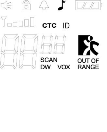
3.1 ICONS on LCD
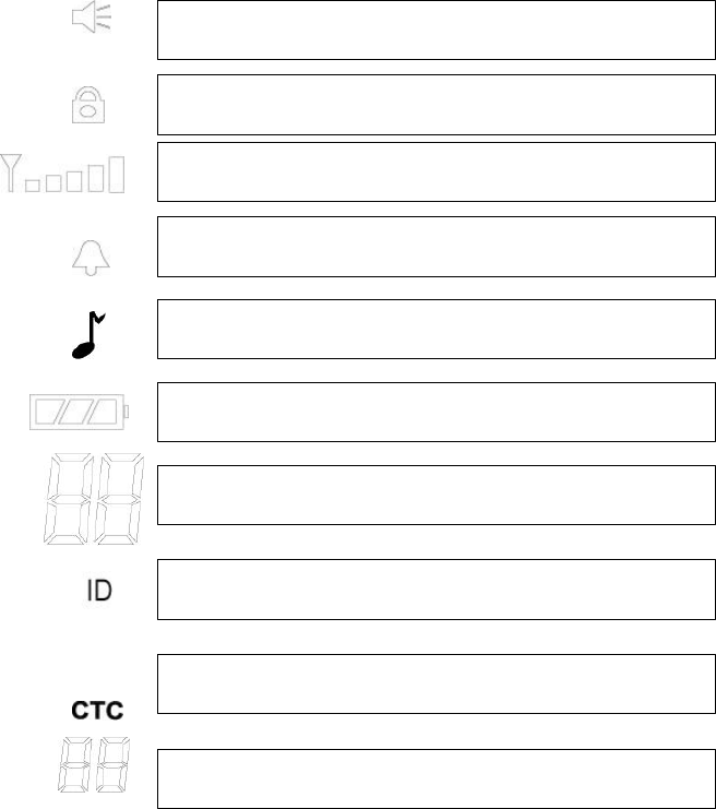
1) Monitor indicator : Appears when the CTCSS isn’t in use and squelch is open.
2) Key lock indicator : Indicates that the key lock function is in use.
3
) Beep ON/OFF indicator : Appears while key tone is in use.
4) Roger On/Off indicator : Appears while Roger tone is in use.
5) Battery indicator : Indicates the battery status
6) Receive signal indicator : Appears when receiving signal or squelch noise is
existing.
7) ID indicator : Appears when the ID function is in use.
8) Channel readout : Shows the current channel number.
9) CTCSS readout : Shows the operating CTCSS frequency or code.
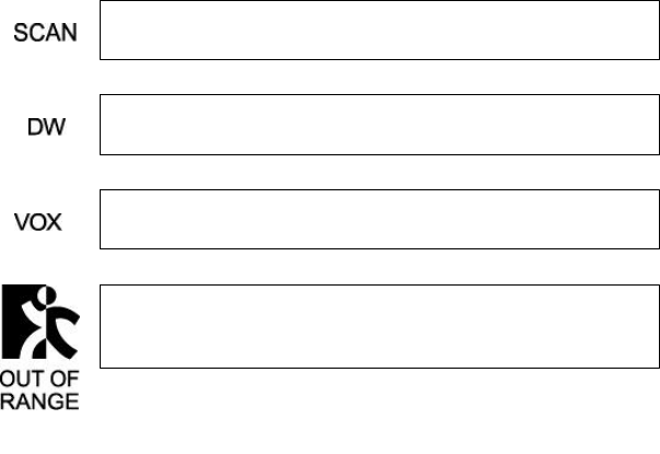
10) SCAN indicator : Indicates that scan is enabled.
11) CTCSS indicator : Appears when the CTCSS function is in use.
12) Dual Watch indicator : Appears when the Dual Watch function is in use.
13) Out Of Range indicator : Appears when the Out Of Range function is in use.
14) VOX (Voice Activated Transmit) Indicator : Turning on the
power while pressing PTT button activates VOX function.
3.2 Key Function
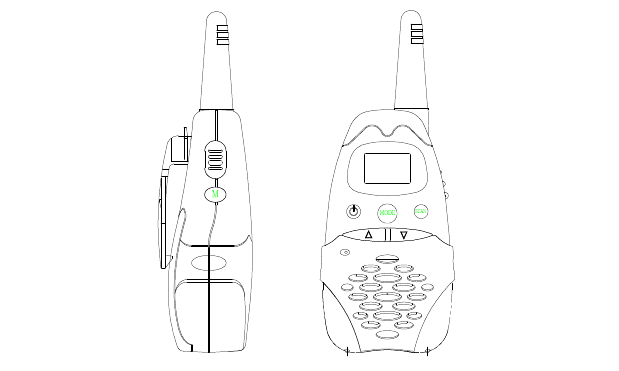
6/21
1) PTT switch : Push and hold to transmit ; release to receive.
2) Monitor : Press and hold this key for over 2 seconds to enable the receive
CTCSS feature.
3) Up/Down key : In the stand-by mode, Pressing this button will increment or
decrement the listening volume. When in function edit mode,
this button will be used to adjust the unit settings..
4) Scan / Lock key : Push this key to momentarily to enable or disable the
scan. Press and hold this key for over 2seconds to lock or
unlock keypad.
5) Mode (Function) key : Push to select the following function setting mode.
Brief press mode : 1'st press – Channel ,
2’nd press – CTCSS,
3’rd press – VOX level,
4'th press – Dual Watch Channel,
5’th press – Roger On/Off,
6'th press – Beep On/Off,
7’th press – Out Of Range On/Off,
8’th press – ID,
9’th press – Call
6) Speaker / Microphone
7
) LCD (Liquid Crystal Display)
8) Transmit / Receive indicator : When receiving an incoming signal, the LED
indicator will light green, and while the PTT
7/21
button is pressed, the LED will light red.
These LED’s are used for backlighting as
well.
9
)External speaker/mic jacks : Connect an optional speaker/mic or headset,
if desired. The internal mic and speaker will not
function when e
ither is connected.
2) Function display
Monitor Indicator: Icon appears when the monitor button is pressed and the channel
monitor function is activated.
Key Lock Indicator: Icon appears when the keypad is locked. This function
disables keys such as channel up/down and mode.
Signal Strength Indicator: Icon appears when a signal is being received. The Icon
consists of five bars to indicate the received signal level.
Beep Tone Indicator: Icon appears when beep tone confirmation tone is selected.
Icon disappears when tone is off.
Roger Beep Tone On/Off Indicator: Icon appears when the roger beep tone is
selected. Icon disappears when tone is off.
Battery Level Indicator: Icon indicates the battery charge level.
Large Segment Display: Indicates the channel number in use.
Caller ID Indicator: Icon appears when caller ID fun
ction is turned on. Icon
disappears when the function is off. This work with small segment display.
Coded Tone Controlled Squelch System(CTC) Indicator: Icon appears when the
CTCSS tone function is active.
Small Segment Display: Displays CTCSS tone option in the channel from 00 to 38,
and also displays the caller ID number(01–10) when caller ID function is active.
8/21
3-3. SETTING AND OPERATION
In order to communicate with other FRS units, both you and the
receiving party must be on the same channel.
FRS 3000-PK has 14channels indicated by the large digits on the
LCD display panel. Before trying to transmit on the selected channel,
you should press the Monitor Button to check the activity on that channel.
If someone is already on the selected channel, you should try another
channel that is clear
1) On/Off & Volume control Switch
Radio ON : Press the power button at least for 2 seconds.You will hear
confirming melody to indicated the unit is on.
Radio OFF : Press the power button at least for 2 seconds.
Volume setting : Press up[ù]or down[ü] button to adjust a level that is most
comfortable for you while monitor is active.
2) Setting the Channel and Tone Code(CTCSS)
FRS 3000-PK has 14 main channels and 38 sub-channels.
* 14 Frequency channels
* 38 CTCSS Code ( indicated by CTC icon on the LCD )
14) Channel readout : Shows the current channel number .
Scan Indicator: This function allows users to scan a channel to search for a valid
signal.
Dual Watch mode Indicator: Icon appears when dual watch mode is active.
Voice Activated Transmission (VOX) Indicator: This function allows handsfree
conversation. The Icon appears when the VOX mode is activated.
Out of Range Al
arm Indicator: When this function is active, Icon blinks the
receiving signal is getting weaker. The Icon stops blinking when the receiving
signal comes back to the normal strength.
9/21
To select the channel
* Turn the radio on.
* Press MODE button once, [XX] digit will blink on the LCD. XX is a channel.
* Press up[ù]or down[ü] button to choose the channel.
* Press the PTT button or MODE button to confirm.
To set the tone codes(CTCSS)
* Press MODE button once more, [XX 00 up to 38] will appear and CTC icon
and tone code digit will blink on the LCD. “00” means no CTCSS code.
* Press up[ù]or down[ü] button to choose the desired sub-channel to use.
* Press the PTT button or MODE button to confirm.
NOTE : To communicate with other FRS units, they must be switched to
the same channel and CTCSS sub-code. To communicate
with other GMRS units that do not have sub-codes, switch your unit
to the same channel with the sub-code set to OFF.
3) VOX (Voice Operated Switching)
This option enables you to have hands-free conversation. You do not have to
operate the PTT button each time when you want to transmit.
You can also choose the VOX sensitivity so suit your environment of operation.
( Ex : noisy road, motor bike, factory etc. )
To Set the VOX mode
* Press the MODE button until the [Uo oF Or XX] appears. XX is a vox level
* VOX icon will be appeared on the LCD.
To Set the VOX level
* Press the up[ù]or down[ü] button to set the VOX level from 1 to 5.
“oF” is disable the VOX function.
“01” is least sensitive.
“05” is most sensitive.
* Press the PTT button or MODE button to confirm.
4) Setting the DW (dual watch)
To set the DW mode
* Press the MODE button until the [ oF of 01 up to 15] and DW icon blink on
the LCD.
* DW icon will appear on the LCD.
To set the dual watch(DW) channel
* Press the up[ù]or down[ü] button to choose the channel.
“oF” means no DW mode.
10/21
“01 up to 15” means the channel that is dual-watched.
* Press the PTT button or MODE button to confirm.
5) Roger tone
This feature will give the tone signal to other parties when transmitting finished
(when PTT button is released.)
To activate or disable the Roger tone
* Press the Mode button until [rb on or oF] and the roger icon blink on the
LCD.
* Press the up[ù]or down[ü] button.
* Press the PTT button or MODE button to confirm.
6) Beep tone
To set the beep tone
* Press the Mode button until [bP on or oF] and the BELL icon blink on the
LCD.
* Press the up[ù]or down[ü] button.
* Press the PTT button or MODE button to confirm.
7) Setting Out of Range
To set the Out of Range
* Press the Mode button until [ir on or oF] and the Out of Range icon blink
on the LCD.
* Press the up[ù]or down[ü] button.
* Press the PTT button or MODE button to confirm.
8) Setting ID code
To set the Caller ID
l Press the MODE button until the ID Icon and small segment display blinks.
l Then press the Up or Down button to select the desired ID number from 01
to 10. “oF” means no ID mode.
l Press the PTT button or Mode button momentarily to confirm the ID
number.
** When a signal is received from the radio where the one Caller ID is selected,
the radio that is receiving the signal displays the Caller ID number of the
transmitting radio.
11/21
9) Call Ringer Selection Mode
This feature Provides 3 user selectable call ringer signal.
To set your favorite call ringer signal.
* Press the MODE button until the [C 01 or up to 03] appears on the LCD.
* Press the up[ù]or down[ü] button to select the call melody type.
* Press the PTT button to confirm.
* To activate the call, click the “PTT” button twice quickly.
10) Transmitting
* Press and hold the PTT button (The LED light red during transmission.)
* Speak slowly and clearly
* To Stop the transmission, release the PTT button.
* if there are no more receiving signal for 5 seconds, the unit will go into
power save mode.
11) Receiving
The Coding feature reduce the possibility of interference and provide enhanced
Communication. You can only listen to a call that has correct matching code.
** Upon receiving a signal, the LED lights green. When radio is on CTCSS mode
and then a signal that has different CTCSS code on the same channel is received,
the LED blinks in green.
Important :
Before transmitting or receiving to the other parties
* Correct channel is selected (1 to 14) and
* Correct code is set ( 00 to 38 )
12) Channel Scanning
This feature allows you to monitor all activated channels while scanning.
To activate the Scan
* Press the SCAN button
* Radio will begin scanning.
* When in scan mode, the display will show each scanning channel.
* After an activated channel is scanned and received signal and then if there is
no more signal, the scan will resume automatically
** Once a channel has been scanned, pushing the monitor button makes the
radio resume the scanning with the scanned channel skipped.
13) Call
* Click the PTT button twice quickly.
12/21
14) Monitoring the Channel
It is used for listening the week signal or to here all activities on the channel by
Manually overriding channel sub tone code setting.
To activate the monitor feature
* Press and hold the “MON”(monitor) button for over two seconds.
* When you hear the sound, release the “MON” button.
( The monitor icon will appear on the LCD.)
To disable the monitor feature
* Press and hold the “MON”(monitor) button for over two seconds.
( The monitor icon will disappear on the LCD.)
15) Keypad Lock
The lock function is to avoid the accidental changes to channel with other radio
settings. All buttons will be locked except the Power, PTT, Monitor, Charger
and Volume UP/Down.
To lock the keypad
* Press and hold the “SCAN” button for over two seconds.
* Keypad will lock. (LOCK icon will appear on the LCD)
To disable the monitor feature
* Press and hold the “SCAN” button for over two seconds.
* Keypad will unlock. (LOCK icon will disappear on the LCD)
16) Battery status indicator
The Battery icon will blink when the radio is in low battery power.
Charge the rechargeable battery or replace the batteries.
* Full battery – three segments are displayed.
* Low battery – one segments is displayed
* Low battery Warning – one segments will brinking.

13/21
4. ADJUSTMENT
4-1. Frequency synthesizer
a) After connecting the power meter and dummy load(50 ohm), join the
antenna connector of FRS 3000-PK with above equipment.
b) Check the voltage between RF BOARD BT POINT & GND in digital volt
meter
c) Then set the low channel of FRS 3000-PK the lowest frequency.
d) After pressed PTT key of FRS 3000-PK, check if the lowest frequency of
Tx channel to DC 1.5V in the voltage of test point(VT).
e) After releasing the PTT key of FRS 3000-PK, check if the highest frequency
of Rx channel is within DC 1.0V in the voltage of test point(VT).
4-2. Transmitter
a) Connect EUT & measure equipment according to block diagram below.
Power Supply
EUT
AF Oscillator
Modulation Meter
Oscillator
AV VTVM
Distortion Meter
Spectrum Analyzer
Frequency Counter
Power Meter Dummy Load
14/21
b) Connect DC 6.0V voltage preset to EUT.
c) Connect ‘Power Meter’ and ‘Dummy Load ( 50)
d) Adjust Tx frequency according to trimming trimmer VC1.
e) Connect AF Oscillator to mic terminal for conform modulation degree.
f) Adjust the frequency of AF Oscillator to 1 kHz and adjust AF level
Should be 100mV.
g) Checking Oscilloscope and Modulation Meter.
Max deviation should be in ±5 kHz.
4-3. Transmitter Test
a) Output Power Test
Power(DC 6.0V) should be Max. 500 mW(ERP) and in –50% range.
b) Audio Response
Connect AF oscillator to Mic terminal and then firm the audio level
that doesn’t distortion the wave of Oscilloscope in the frequency range,
300Hz~ 3kHz. Check the audio level for 300Hz~ 3kHz based on frequency
standard,1kHz.
c) Modulation Degree Test
1) Connect AF oscillator to the MIC terminal and then adjust the level
to 100
2) Measure the Oscilloscope wave and the point needle of Modulation Meter
after pressing PTT key.
3) Sweep gradually the frequency of AF Oscilloscope from 300Hz to 3kHz.
4) At this time, the point needle of Modulation Meter should be in ±5 kHz
d) Spectrum Test
1) Antenna is 50and attenuation degree should be 20 more.
2) Observe the Spectrum with pressing PTT key.
The harmonics should be less –36 ~ -30dBm than carrier.
4-4. Receiver
a) Preparation
1) Adjust the power supply to DC 6.0V.
2) Adjust Voltage level to 0.5Vrms(8load) after power on.

15/21
b) Connection method
c) The Conform of Rx sensitivity
1) Adjust SSG to channel frequency.
2) Adjust modulation frequency , 1Khz to modulation degree, 3kHz.
3) After adjusting the frequency of SSG to channel frequency, RF level
sets to –47dBm.
d) The Conform of Squelch sensitivity
1) Set the standard channel.
2) In squelch mode, SQ volume VR2 must be turned counterclockwise.
3) After adjusting SSG to channel frequency, the RF level of SSG is set
On SINAD 10~6 .
4-5. Receiver Test
a) Rx sensitivity test
SSG should be adjusted to 12 of SINAD point needle seeing wave of
Oscilloscope as SSG sets in 1kHz frequency deviation.
At this time , normal RF level is –110 ~ -107dBm.
b) Audio Distortion Test
1) SSG should be adjusted like way of point “a)” and RF level sets to
-47 dBm.
2) Adjust to 0.7Vrms(4load) seeing Audio wave.
3) Read the needle of Distortion Meter (Normal condition would be less
Then 5% distortion)
c) Squelch Test
After RF level of SSG should be set to the least level, RF level should be
Gradually increased until speaker makes audio sound.
At this point, check RF level (Check if the SINAD is 10~6 ).
SSG EUT 4Load
Oscilloscope
AV VTVM
Distortion Meter
SINAD Meter
Power Supply
16/21
4-6. Symptoms, Check point & Correction
a) Diagnosis method
1) Check each switch to work well.
2) Check voltage of battery.
3) Problem develops from transmitter or receiver?
b) Troubleshooting
1) Transmitter
-. Power key is on condition but does not work.
Battery could completely discharge.
Battery cell twist ..
Touch problem come between Battery and Radio.
-. Fail to transmit.
Run out of battery or charge problem.
Fault of PTT key.
Fault of Q4,Q3,Q2.Q1
-. Transmitter works but frequency is unmatched
Out of order in frequency synthesizer.
Out of order in X-tal frequency(X2)
-. Audio does not sound (Tx power and Tx frequency are normal)
Problem of microphone or mic connector.
-. Tx is set when switch is on
Tx switch(PTT) problem.
2) Receiver
-. Rx does not work
Speaker line open problem or connector problem.
Receiver power circuit problem.
Audio amplifier Base band IC U2 problem.
-. Only noise sound
17/21
IF IC U8 problem.
VCO circuit problem.
-. Rx sensitivity is weak
Antenna mounting problem.
Receiver front-end circuit problem.
Local oscillation frequency deviation.
FL1,FL2 SAW filter fail.
VCO circuit problem.
-. Squelch does not work
IF IC U8 problem.
Control logic circuit problem.
18/21
5. DESCRIPTION OF RADIO CIRCUIT
5-1. Frequency synthesizer
Frequency synthesizerconsists of VCO, loop filter and RFIC. RFIC includes
MIX,IF, Compander and PLL. Frequency synthesizer uses the PLL of thte RFIC.
a) VCO
VCO is composed of ONE VCO
Oscillation circuit takes colpitts circuit using variable Diode. The VCO
generates FRS frequencies and consists of L17, D5, C65, L19, C69, C70, R45,
R44, R46, C71, C72, Q14, R47, C74, R48, Q15, L29, C147, C151.
VCO control voltage through loop filter adjusts frequency and Microphone
Signal through Modulation terminal makes modulation.
N = VCO oscillation frequency / reference frequency
If the desired frequency is 462.5625 MHz
1) TX : N = 462.5625 MHz / 0.00625 MHz = 74010
2) RX : N = [462.5625 MHz – 21.7 MHz] / 0.00625 MHz = 70538
b) PLL IC
RFIC(PLL) is adjustable IC to produce the wished frequency which VCO
provides through loop filter. It has internal counter using 21.25Mhz
reference frequency to make 6.25kHz as reference Signal. VCO frequency
from prescaled input is divided signal is compared with Reference signal
phase in phase comparator. Built-in charger pump changes voltage (until two
signals are in phase) and charged voltage supplies VCO through loop filter
to produce the desired frequency.
Frequency data associated with channel goes to PLL IC by CPU through
CLOCK , DATA. PLL IC enables by strobe line of CPU.
c) Loop Filter
Loop filter is composed of C98, R77, C37,R78, C102, R79 and changes
pulse from U2.46 to DC . And eliminates harmonic component in pulse.
It helps VCO oscillate clearly as DC voltage is supplied into Varicap.
5-2. Receiver
This is composed of Dual Conversion Super Heterodyne. First IF is 21.7Mhz.
Local oscillator frequency is lower in 1’st IF than Rx frequency.
It is called low side injection. Second IF is 450kHz . 2’nd local oscillator
Frequency comes to 21.25MHz.
a) Rx / Tx Conversion Circuit
Rx signal goes to Rx / Tx conversion circuit through FIXED antenna
connector, low pass filter (L1,L2,L3,C6,C1,C2,C3,C4,C5) and receiver
resonance circuit composed of L4,C24. When transmitting,
Voltage through R1,L5,D1 supplies,D2 of receive input is short and
Tx is on condition. When PIN diode is off in condition of Rx, C25,C86
19/21
L21,C87 resonate serially and make impedance matching at receiver band-
pass filter.(FL1,FL2)
b) Front End
Front-end has Q6 to provide a high sensitivity and low noise feature.
It employs SAW filter as band pass filter to eliminate image frequency
and to produce enough pass band by Q6 input and output.
c) 1st Mixer
The receiver which has been amplifier in the RF front-end is provided to the
base of the 1st mixer Q7. The 1st L/O signal provide from the VCO is supplied
to the emitter of Q7 and Converted to the 1st IF 21.7 MHz
d) 1st IF Filter
The signal covered by Q7 to 21.7 MHz, the 1
st frequency, change its
impedance through C48, and then is infused to the fundamental MCF which
has the center frequency of 21.7 MHz and the width of +/- 3.75 KHz.
Here, the signal reduces the image and other unwanted signal for the 2nd IF ,
and changes its impedance again through the R24. This filtered signal flows
in the 1st IF amplifier of RFIC(U2).
e) 2nd Mixer, and IF, FM Detect (U2)
The receiver IF signal of 21.7 MHz, which has been infused to U2 is mixed
with the 2nd L/O converted to 450 KHz, the 2nd IF frequency. The receiver
signal converted to the 2nd IF signal frequency passed through the FL3, the
ceramic filter of 450 kHz again.
The squelch circuit is composed to detect the noises from the received signal
demodulate in the 40th pin of the U2. For this purpose, the noise filter is using
the OP amplifier inside the U2
f) CTCSS Detector(U3, U4)
The 2nd IF frequency comes from No.26 pin of U2 and goes to MPU through
the active filter having U3 and U4.
g) Audio Amplifier(U10)
Demodulated audio signal enters to pin3 of AF IC (U10).
It comes out to pin5 then, it reaches at speaker.
5-3. Transmitt
When Tx develops with pressing PTT switch, VCO output amplifies through
Q3,Q2,Q1,Q12,Q16 transmits by antenna through low pass filter.
Tx RF signal produced from Tx VCO is amplified by Buffer Q3, Driver Q2
through C14, L11 and entered Q1,Q12,Q16 Power Transistor input
terminal with final amplification. After this stage, the signal is emitted at
antenna through 50matching circuit to low pass filter (L3,L2,L1,C6,C5
C4,C3,C2,C1) to eliminate harmonic.
a) Audio Modulation and Audio Amplification
Audio signal produced by external or internal microphone, limits
amplification, low pass filter by IC U4.
20/21
Max. Frequency modulation deviation is adjusted by U4,VR1 keeps noise and
audio from entering to VCO at time of Tx. Audio modulation and Audio
Amplification has characteristic of 6 /OCT pre-emphasis by U4.
9. EXPLODED VIEW
21/21
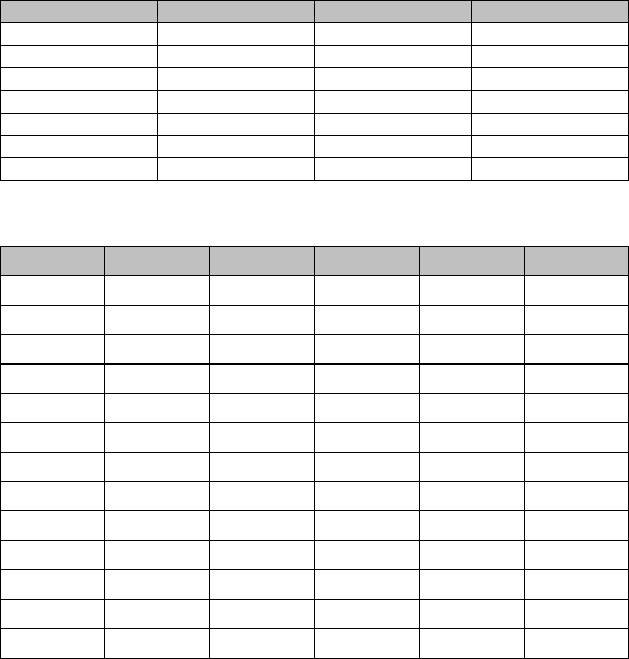
10. CHANNEL DATA
1) FRS Frequency Chart
Channel Frequency (MHz) Channel Frequency (MHz)
1 462.5625 8 467.5625
2 462.5875 9 467.5875
3 462.6125 10 467.6125
4 462.6375 11 467.6375
5 462.6625 12 467.6625
6 462.6875 13 467.6875
7 462.7125 14 467.7125
2) CTCSS Tone Frequency Chart
NO FREQ.(Hz) NO FREQ. (Hz) NO FREQ. (Hz)
1 67.0 14 107.2 27 167.9
2 71.9 15 110.9 28 186.2
3 74.4 16 114.8 29 179.9
4 77.0 17 118.8 30 186.2
5 79.7 18 123.0 31 192.8
6 82.5 19 127.3 32 203.5
7 85.4 20 131.8 33 210.7
8 88.5 21 136.5 34 218.1
9 91.5 22 141.3 35 225.7
10 94.8 23 146.2 36 233.6
11 97.4 24 151.4 37 241.8
12 100.0 25 156.7 38 250.3
13 103.5 26 162.2 OF 0