TTI Tech GMRS-7000 GRMS Transceiver User Manual Manual
TTI Tech Co., Ltd. GRMS Transceiver Manual
TTI Tech >
Contents
- 1. User Manual
- 2. revised user manual to include RF exposure info
- 3. CRN 22241 Revised RF exposure information in user manual
CRN 22241 Revised RF exposure information in user manual
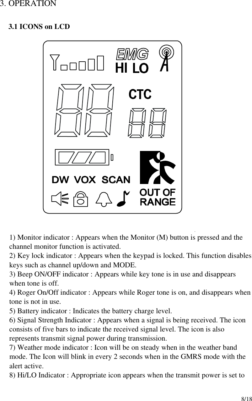
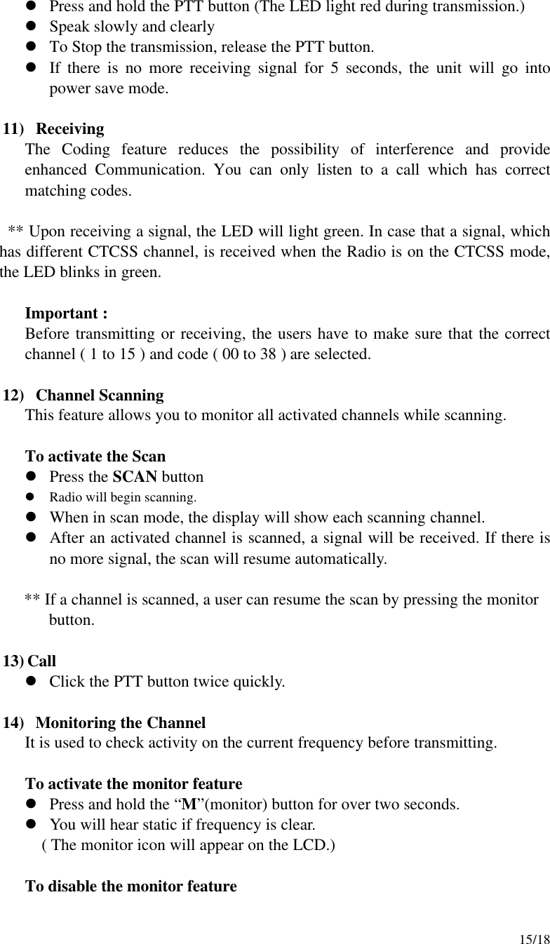
![12/18 3-3. SETTING AND OPERATION In order to communicate with other GMRS/FRS units, both you and the receiving party must be on the same channel. GMRS-7000 has 15channels indicated by the large digits on the LCD display panel. Before trying to transmit on the selected channel, you should press the Monitor Button to check the activity on that channel. If someone is already on the selected channel, you should try another channel which is clear 1) On/Off & Volume control Switch Radio ON : Press the power button at least for 2 seconds.You will hear confirming melody to indicate the unit is on. Radio OFF : Press the power button at least for 2 seconds. Volume setting : Press up[]or down[ ] button to adjust a level comfortable for you while monitor is active. 2) Setting the Channel and Tone Code(CTCSS) GMRS-7000 has 15 main channels and 38 sub-channels. l 14 Frequency channels l 38 CTCSS Code ( indicated by CTC icon on the LCD ) To select the channel l Turn the radio on. l Press MODE button once, [XX] digit will blink on the LCD. XX is a channel. l Press up[]or down[ ] button to choose the channel. l Press the PTT button or MODE button to confirm. To set the tone codes(CTCSS) l Press MODE button once more, [XX oF, 01 up to 38] will appear and CTC icon and tone code digit will blink on the LCD. “oF” means no CTCSS code. l Press up[]or down[ ] button to choose the desired sub-channel to use. l Press the PTT button or MODE button to confirm. NOTE : To communicate with other GMRS/FRS units, they must be switched to the same channel and CTCSS sub-code. To communicate with other GMRS/FRS units which do not have sub-](https://usermanual.wiki/TTI-Tech/GMRS-7000.CRN-22241-Revised-RF-exposure-information-in-user-manual/User-Guide-231810-Page-12.png)
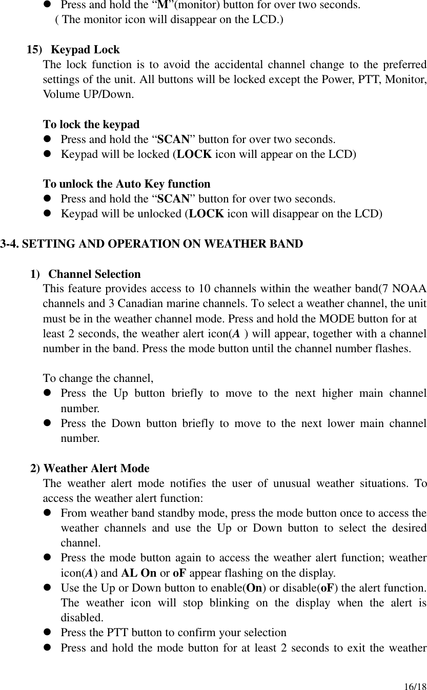
![13/18 codes, switch your unit to the same channel with the sub-code setting to OFF. 3) VOX (Voice Operated Switching) This option enables you to have hands-free conversation. You do not have to operate the PTT button each time when you want to transmit. You can also choose the VOX sensitivity suit your environment of operation. ( Ex : noisy road, motor bike, factory etc. ) To Set the VOX mode l Press the MODE button until the [Uo oF or XX] appears. XX is a vox level l VOX icon will be appeared on the LCD. To set the VOX level l Press the up[]or down[] button to set the VOX level from 1 to 5. “oF” is disable the VOX function. “01” is least sensitive. “05” is most sensitive. l Press the PTT button or MODE button to confirm. 4) Setting the DW (dual watch) To set the DW mode l Press the MODE button until the [ oF of 01 up to 15] and DW icon blink on the LCD. l DW icon will appear on the LCD. To set the dual watch(DW) channel l Press the up[]or down[] button to choose the channel. “oF” means no DW mode. “01 up to 15” means the channel is dual-watched. l Press the PTT button or MODE button to confirm. 5) Power Selection Mode This feature permits selection of the transmitting power level to high or low. Using low power, the unit will have a lower transmit range but battery life will Be increased. To access the transmitter power selection function l Press the MODE button until the Po icon appears with a flashing Hi or Lo indication on the display.](https://usermanual.wiki/TTI-Tech/GMRS-7000.CRN-22241-Revised-RF-exposure-information-in-user-manual/User-Guide-231810-Page-13.png)
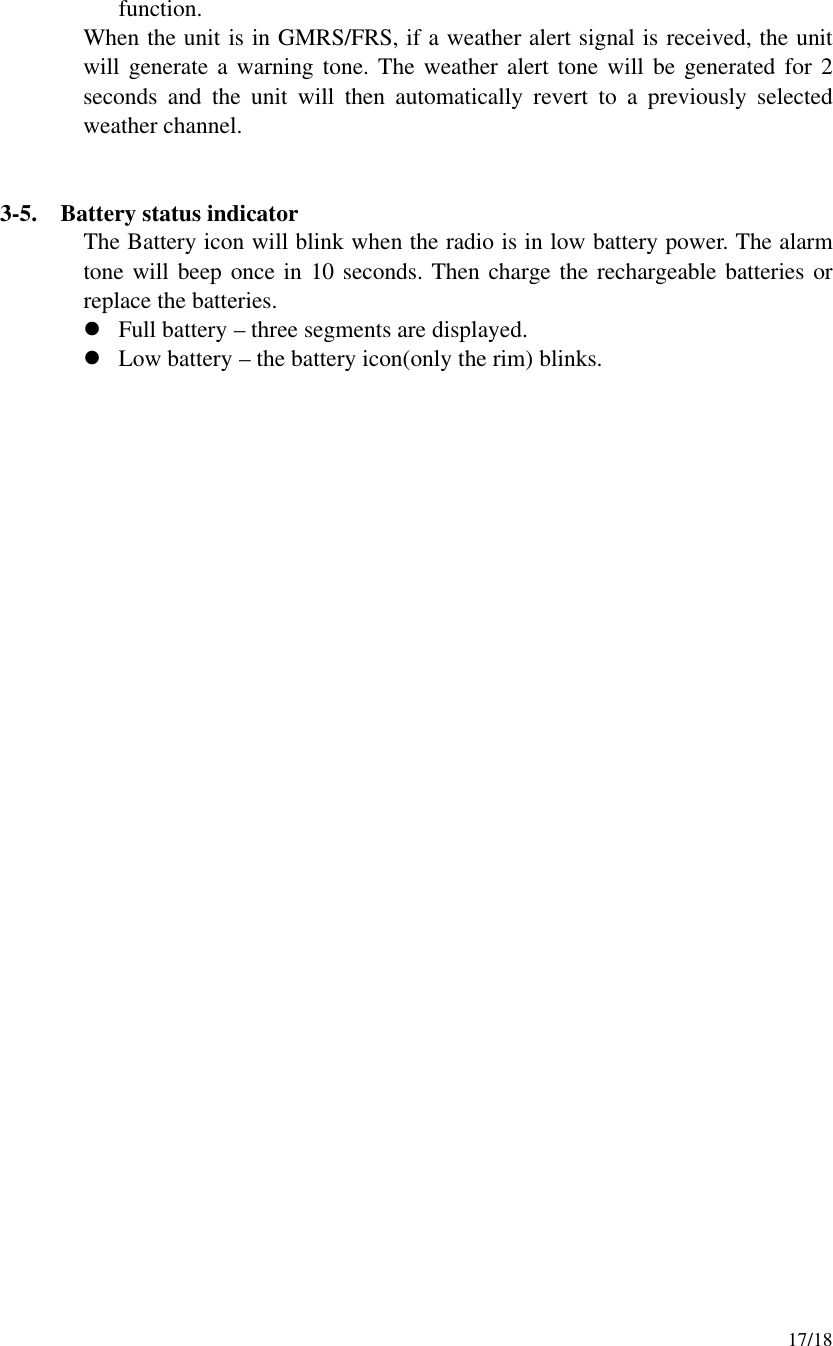
![14/18 l Press the Up or Down button to toggle between the Hi or Lo selections. l Press the PTT button momentarily to confirm selection. 6)Roger tone This feature will give the tone signal to other parties when transmitting is finished (when PTT button is released.) To activate or disable the Roger tone l Press the Mode button until [rb On or oF] and the roger icon blink on the LCD. l Press the up[ ]or down[ ] button. l Press the PTT button or MODE button to confirm. 7) Beep tone Hearing this tone, users will make sure that any button has been correctly pressed. To set the beep tone l Press the Mode button until [bP On or oF] and the BELL icon blink on the LCD. l Press the up[]or down[] button. l Press the PTT button or MODE button to confirm. 8) Call Ringer Selection Mode This feature Provides 3 user selectable call ringer signal. To set your favorite call ringer signal. l Press the MODE button until the [C 01 or up to 03] appears on the LCD. l Press the up[]or down[] button to select the call melody type. l Press the PTT button to confirm. l To activate the call, click the “PTT” button twice quickly. 9) Out-of-range Alarm Icon blinks as the receiving signal is getting weaker. The Icon stops blinking when the receiving signal comes back to normal strength. 10) Transmitting](https://usermanual.wiki/TTI-Tech/GMRS-7000.CRN-22241-Revised-RF-exposure-information-in-user-manual/User-Guide-231810-Page-14.png)