TTI Tech GMRS-7000 GRMS Transceiver User Manual revised to include RF exposure info
TTI Tech Co., Ltd. GRMS Transceiver revised to include RF exposure info
TTI Tech >
Contents
- 1. User Manual
- 2. revised user manual to include RF exposure info
- 3. CRN 22241 Revised RF exposure information in user manual
revised user manual to include RF exposure info
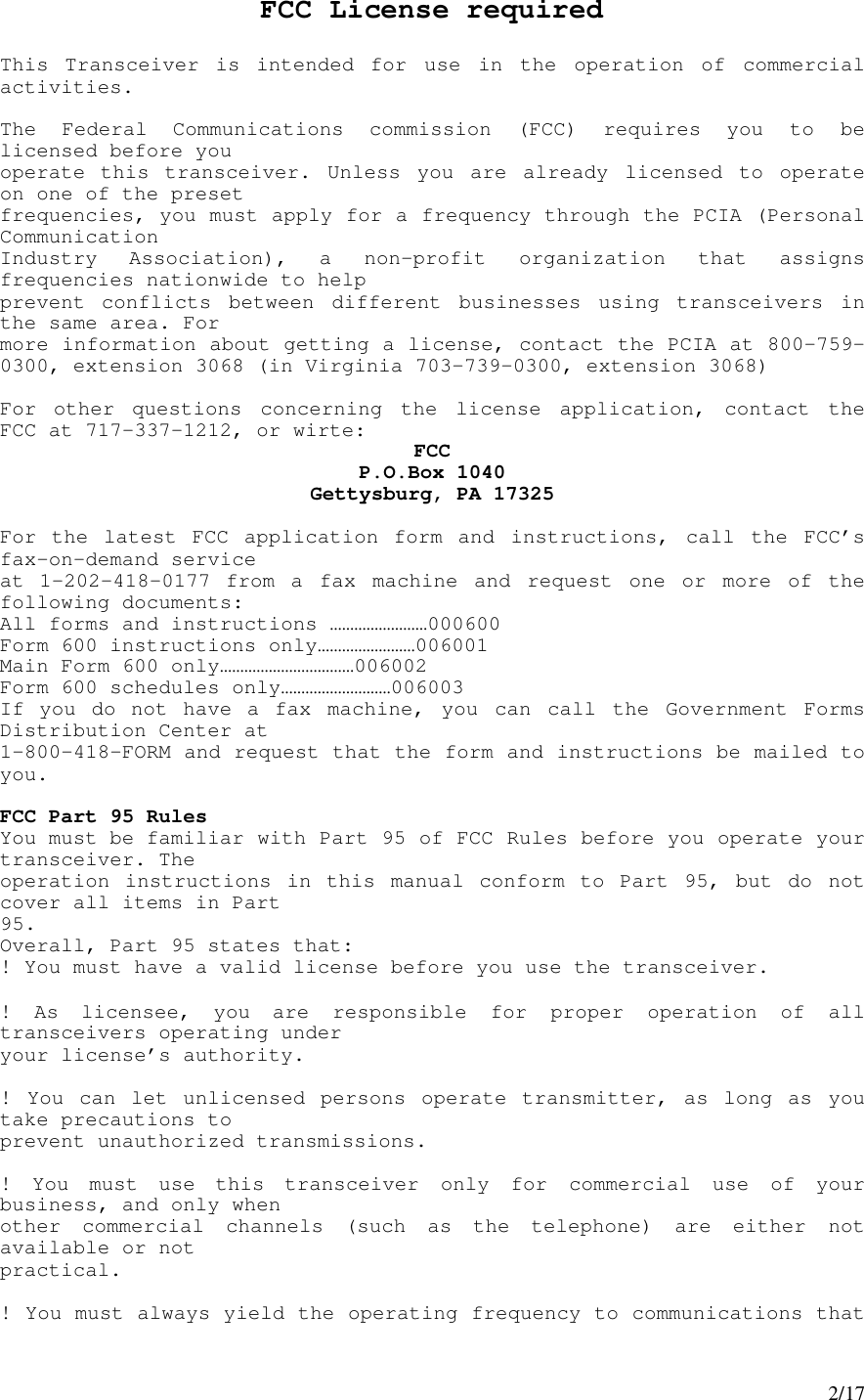
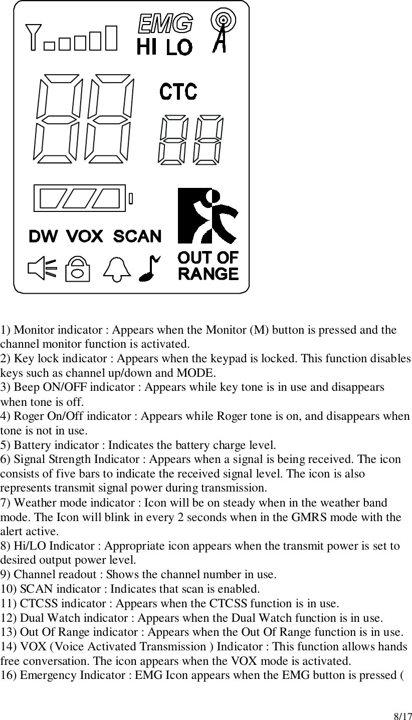
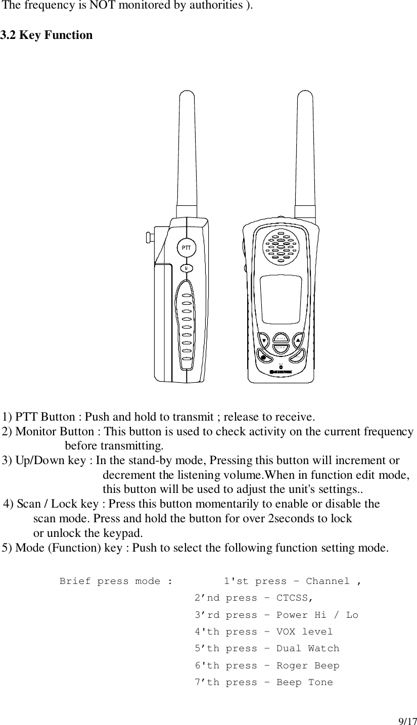
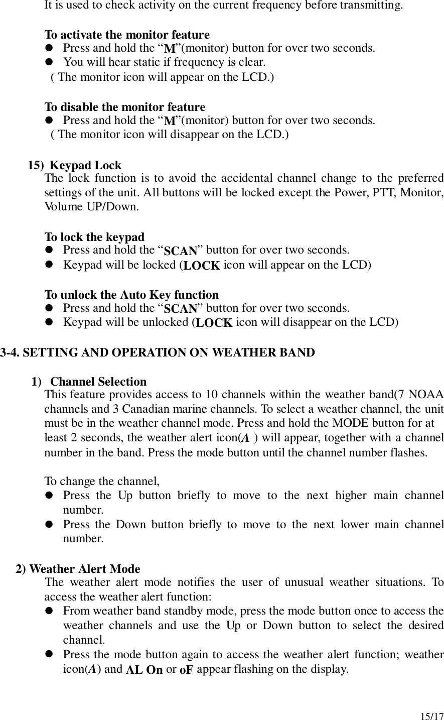
![11/173-3. SETTING AND OPERATIONIn order to communicate with other GMRS/FRS units, both you and the receiving party must be on the same channel. GMRS-7000 has 15channels indicated by the large digits on the LCD display panel. Before trying to transmit on the selected channel, you should press the Monitor Button to check the activity on that channel. If someone is already on the selected channel, you should try another channel which is clear1) On/Off & Volume control SwitchRadio ON : Press the power button at least for 2 seconds.You will hearconfirming melody to indicate the unit is on. Radio OFF : Press the power button at least for 2 seconds.Volume setting : Press up[″]or down[…] button to adjust a level comfortablefor you while monitor is active.2) Setting the Channel and Tone Code(CTCSS)Coded Tone Controlled Squelch System(CTC) Indicator: Icon appears when theCTCSS tone function is active.Small Segment Display: Displays CTCSS tone option in the channel from 00 to 38,and also displays the caller ID number(01–10) when caller ID function is active.Dual Watch mode Indicator: Icon appears when dual watch mode is active.Voice Activated Transmission (VOX) Indicator: This function allows handsfreeconversation. The Icon appears when the VOX mode is activated.Out of Range Alarm Indicator: Icon blinks as the receiving signal is getting weaker.The Icon stops blinking when the receiving signal comes back to the normalstrength.Weather Mode Indicator: Icon will be on steady when in the weather band mode.The icon will blink when in the GMRS mode with the alert active.](https://usermanual.wiki/TTI-Tech/GMRS-7000.revised-user-manual-to-include-RF-exposure-info/User-Guide-224499-Page-11.png)
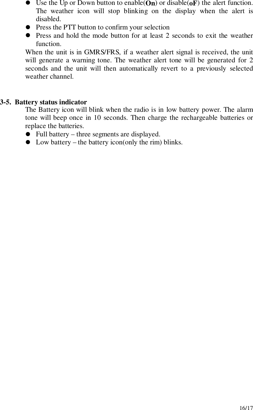
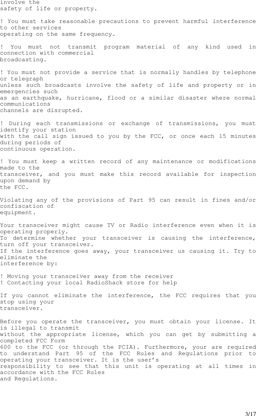
![12/17GMRS-7000 has 15 main channels and 38 sub-channels.! 14 Frequency channels! 38 CTCSS Code ( indicated by CTC icon on the LCD )To select the channel! Turn the radio on.! Press MODE button once, [XX] digit will blink on the LCD. XX is achannel.! Press up[″]or down[…] button to choose the channel.! Press the PTT button or MODE button to confirm.To set the tone codes(CTCSS)! Press MODE button once more, [XX oF, 01 up to 38] will appear and CTCicon and tone code digit will blink on the LCD. “oF” means no CTCSScode.! Press up[″]or down[…] button to choose the desired sub-channel to use.! Press the PTT button or MODE button to confirm.NOTE : To communicate with other GMRS/FRS units, they mustbe switched to the same channel and CTCSS sub-code. Tocommunicate with other GMRS/FRS units which do not have sub-codes, switch your unit to the same channel with the sub-code settingto OFF.3) VOX (Voice Operated Switching)This option enables you to have hands-free conversation. You do not have tooperate the PTT button each time when you want to transmit.You can also choose the VOX sensitivity suit your environment of operation.( Ex : noisy road, motor bike, factory etc. )To Set the VOX mode! Press the MODE button until the [Uo oF or XX] appears. XX is a vox level! VOX icon will be appeared on the LCD.To set the VOX level! Press the up[″]or down[…] button to set the VOX level from 1 to 5.“oF” is disable the VOX function.“01” is least sensitive.“05” is most sensitive.! Press the PTT button or MODE button to confirm.4) Setting the DW (dual watch)To set the DW mode! Press the MODE button until the [ oF of 01 up to 15] and DW icon blinkon the LCD.! DW icon will appear on the LCD.](https://usermanual.wiki/TTI-Tech/GMRS-7000.revised-user-manual-to-include-RF-exposure-info/User-Guide-224499-Page-12.png)
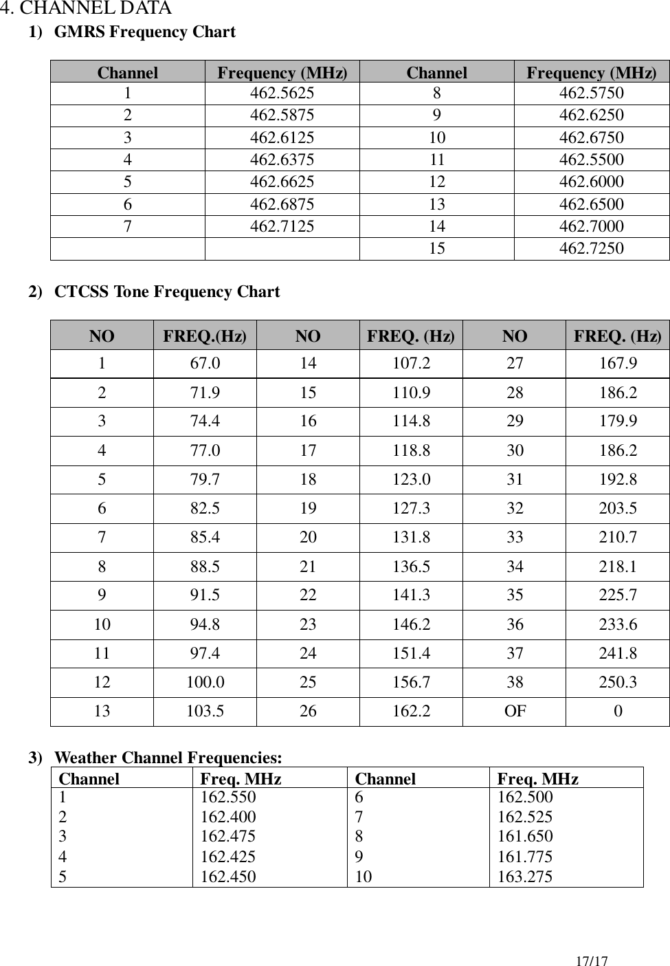
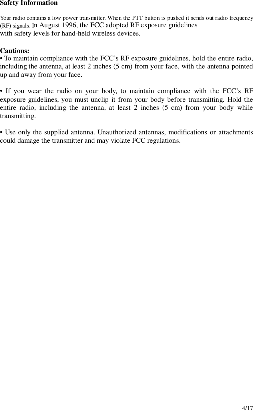
![13/17To set the dual watch(DW) channel! Press the up[″]or down[…] button to choose the channel.“oF” means no DW mode.“01 up to 15” means the channel is dual-watched.! Press the PTT button or MODE button to confirm. 5) Power Selection Mode This feature permits selection of the transmitting power level to high or low. Using low power, the unit will have a lower transmit range but battery life will Be increased. To access the transmitter power selection function! Press the MODE button until the Po icon appears with a flashing Hi or Loindication on the display.! Press the Up or Down button to toggle between the Hi or Lo selections.! Press the PTT button momentarily to confirm selection. 6)Roger toneThis feature will give the tone signal to other parties when transmitting isfinished(when PTT button is released.)To activate or disable the Roger tone! Press the Mode button until [rb On or oF] and the roger icon blink on theLCD.! Press the up[•]or down[•] button.! Press the PTT button or MODE button to confirm.7) Beep toneHearing this tone, users will make sure that any button has been correctlypressed.To set the beep tone! Press the Mode button until [bP On or oF] and the BELL icon blink on theLCD.! Press the up[″]or down[…] button.! Press the PTT button or MODE button to confirm.8) Call Ringer Selection ModeThis feature Provides 3 user selectable call ringer signal.](https://usermanual.wiki/TTI-Tech/GMRS-7000.revised-user-manual-to-include-RF-exposure-info/User-Guide-224499-Page-13.png)
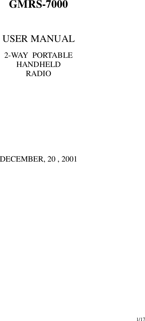
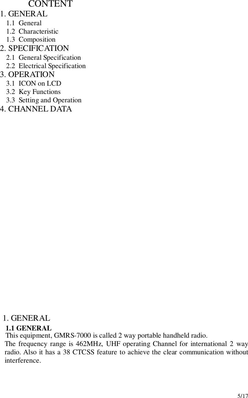
![14/17To set your favorite call ringer signal.! Press the MODE button until the [C 01 or up to 03] appears on the LCD.! Press the up[″]or down[…] button to select the call melody type.! Press the PTT button to confirm.! To activate the call, click the “PTT” button twice quickly.9) Out-of-range AlarmIcon blinks as the receiving signal is getting weaker. The Icon stops blinkingwhen the receiving signal comes back to normal strength.10) Transmitting! Press and hold the PTT button (The LED light red during transmission.)! Speak slowly and clearly! To Stop the transmission, release the PTT button.! If there is no more receiving signal for 5 seconds, the unit will go intopower save mode.11) ReceivingThe Coding feature reduces the possibility of interference and provideenhanced Communication. You can only listen to a call which has correctmatching codes.** Upon receiving a signal, the LED will light green. In case that a signal, whichhas different CTCSS channel, is received when the Radio is on the CTCSS mode,the LED blinks in green.Important :Before transmitting or receiving, the users have to make sure that the correctchannel ( 1 to 15 ) and code ( 00 to 38 ) are selected.12) Channel ScanningThis feature allows you to monitor all activated channels while scanning.To activate the Scan! Press the SCAN button! Radio will begin scanning.! When in scan mode, the display will show each scanning channel.! After an activated channel is scanned, a signal will be received. If there isno more signal, the scan will resume automatically. ** If a channel is scanned, a user can resume the scan by pressing the monitor button.13) Call! Click the PTT button twice quickly.14) Monitoring the Channel](https://usermanual.wiki/TTI-Tech/GMRS-7000.revised-user-manual-to-include-RF-exposure-info/User-Guide-224499-Page-14.png)