TVS Electronics SU-CLASSIC500 Uninterruptible Power Supply User Manual service manual
TVS Electronics Limited Uninterruptible Power Supply service manual
user manual
EXHIBIT C
User Manual
User Manual Power UPS 500 Page 1
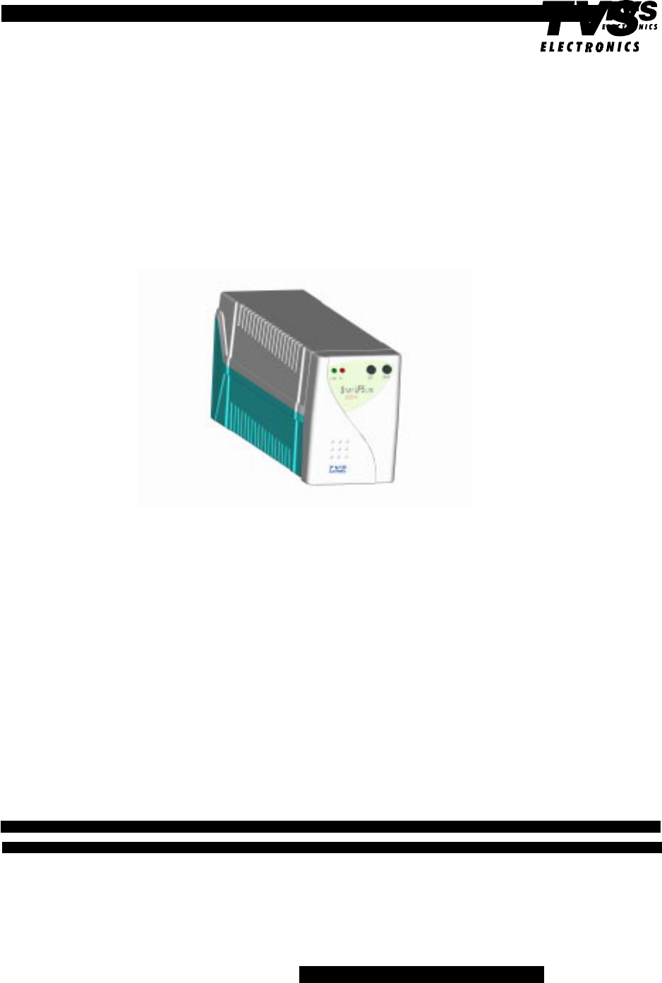
USER MANUAL STARTUPS
LITE 500
REV 1.0
UNINTERRUPTIBLE POWER SUPPLY

User Manual Power UPS 500 Page 2
User Manual Power UPS 500
Dear Customer,
Congratulations on having made an intelligent choice. This product is designed and manufac-
tured with utmost care to give you high quality trouble-free performance in the years to come. Please
register your product by filling the enclosed Business Reply Card and Mailing it to us. This will
enable you to avail free warranty services, in the unlikely requirement of any service assistance.
This registration will also entitle you to receive free mailers on product upgrades, service cam-
paigns, etc. in case you do not find the Business Reply Card in this manual, please write to us for a
new registration card:
Customer support,
TVS Electronics Limited,
No. 34, Developed plots, South Phase,
Industrial Estate, Guindy,
Chennai 600 032.
Please note that it is mandatory to register your product with us. The warranty applicable for
this product is likely to be rejected in case of non-registration of your product with us.
For any queries on our product and/or services you can contact either our branch office or our
authorised service provider. List of service providers are available in this CD.
For any on-line support, please contact your nearest call center, an exclusive Tele-solution
desk available for all TVS-E customers. The contact details are:
E-Mail: careline @esa.tvse.co.in
Carecentre-Chennai :9622012012
Carecentre-Bangalore :6565010/6561679
Carecentre-Mumbai :7905717/7668496
Carefax (Fax on demand):+91-44-2327588
Website :www.tvse.com
OR
TVS Electronics Limited.
No.35:Developed plots, South phase
Guindy industrial Estate
Guindy
Chennai - 600 032.

User Manual Power UPS 500 Page 3
TVS ELECTRONICS LIMITED HARDWARE WARRANTY
What the warranty covers
TVS Electronics Limited, warrants the buyer, that its hardware product sold is free from defec-
tive workmanship or material under normal use and service. If a product proves to be defective in
material or workmanship during the warranty period, we will at our sole option repair or replace the
product with a like product.
How long is the warranty
Power UPS 500 is warranted for 3 years without battery for all manufacturing defects. The
battery is warranted for 1 year. During the warranty TVSE will repair or replace the unit and return
to the Dealer/Distributor/Customer.
Whom the Warranty protects
This warranty is only valid for the first consumer/purchaser.
What the warranty does not cover:
1. Any product on which the serial number has been defaced, modified or removed.
2. Damage, deterioration or malfunction resulting from:
a) Accident, misuse, neglect, fire, water, lightning or other acts of nature. Unauthorised
product modification or failure to follow instruction supplied with the product.
b) Repair or attempted repair by anyone not authorised by TVSE.
c) Repair or attempted repair using components not specified/recommended.
d) Damage due to unauthorised shipment.
e) Removal or installation of the product by unauthorised personnel.
f) Operation not maintained with TVSE specification.
g) Causes external to the product, such as electric power fluctuation or failure, improper
earthing.
h) Use of suppliers or products not meeting our specification.
i) Normal wear and tear due to usage.
j) Any other cause that does not relate to product defects.
3. Reinstallation and Preparation of site for installing the UPS.

User Manual Power UPS 500 Page 4
User Manual Power UPS
We thank you for selecting a TVSE Uninterruptible Power Supply (UPS) and recommend
that you read these instructions carefully before installation and start-up of the Power UPS
500.
Please keep this manual in a safe place for future reference.
Contents
1. Introduction ....................................................................... 6
2. Safety................................................................................ 7
3. Outlook And Function ........................................................ 8
4. Installation ....................................................................... 11
5. Operation ........................................................................ 12
6. Alarms ............................................................................. 13
7. Specifications ...……………………………………………..14
8. On-Battery Run Time Table ............................................. 15
9. Troubleshooting ............................................................... 16
10. About The Battery ........................................................... 17
11. Storage.......................................................................18
12. Communications Port......…...........................................18
13. Frequently asked questions...........................................19
13. How to get service........................................................20

User Manual Power UPS 500 Page 5
1 Introduction
The Power UPS will help you to protect your sensitive equipment like computers and
telecommunication installations against malfunctioning due to non-reliable or distorted mains/
utility/line - voltage
This modern, microprocessor controlled UPS protects the connected equipment against
Surges, Sags, Spikes, etc. by means of an internal filter that works all the time.
During electrical power failures, the unit employs its internal maintenance-free battery to
supply back-up power without any interruption. The UPS is equipped with many features
that will make your equipment to operate more reliable.
The packing kit contains UPS Power UPS 500VA, Output power cable and CD-ROM.
Built-in-Automatic Voltage Regulator: Provides regulated output voltage even under worst
power conditions.
Wide Input voltage range : Minimises calls on battery. Prolongs battery life.
No load shutdown: Avoids unnecessary draining of batteries and increases the battery
life.
User friendly output socket: 3 Indian and 1 European sockets eliminate the need of an
additional power strip.
Surge protected Cyber jack: Protects Modem / Telephone / Network nodes from Light-
ning (High voltage) surges.
Short circuit protection: Protects connected loads from damages due to short circuits
Cold start: Makes it possible to start the UPS and use battery power in the absence of
power.

User Manual Power UPS 500 Page 6
2 Safety
This UPS can be operated by anyone, without any special training, after reading this
manual
WARNING: RISK OF ELECTRICAL SHOCK:
HIGH-VOLTAGE AND HIGH-CURRENT CIRCUITS INSIDE, even if disconnected from the
mains voltage
Do not remove cover, no user serviceable parts inside
Refer servicing to qualified service personnel
CAUTION: THIS EQUIPMENT MUST BE EARTHED AT ALL TIMES WHILST IN USE
Replace batteries only with the same type and rating
Disconnect batteries during maintenance
Do not dispose the batteries in fire. They will explode. Do not open or mutilate the battery.
The content is toxic and harmful to skin and eyes.
Proper disposal or recycling of the battery is required. Refer to the local codes
User Manual Power UPS 500 Page 7
3. Outlook And Function
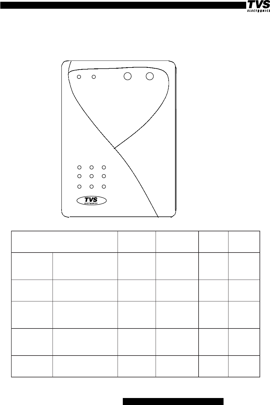
3.1 Front panel
t
LINE BAT. ON OFF
Power UPS
500VA
sutatS noitidnoCtnevE -NEERG/DER )1DEL( WOLLEY/DER )2DEL( rezzuB teseR rezzuB
sniamnoSPU degrahcyllufyrettaB situptuosallewsasniaM elbaliava
NOneerG sounitnoC ---
daolrevO
sniam fo%501>rewoptuptuOyticapacdetareht sounitnocdeR-
rezzuB
sounitnoc
toN
elbissop
yrettaB
tuptuognigrahc
NO
dnaNOtuptuodnasniaM
degrahcylluftonyrettaB NOneerG
sounitnoc gniknilbwolleY
sces4x1
--
yrettaB tuptuognigrahc
ffo
tonyrettaBdnaNOsniaM
degrahcylluf gniknilbneerG
sces4x1 gniknilBwolleY
sces4x1 --
lamronbA
egatloVtuptuo NOdeRNOdeRsounitnoC
toN
elbissop

User Manual Power UPS 500 Page 8
After ‘End Autonomy’ automatic restart possible during 8 hours. After 8 hours restart must
be done manually: press button ‘ON’
sutatS
noitidnoCtnevE
neerG/deR 1DEL wolleY/deR 2DEL rezzuB teseR rezzuB
NOSPU yrettaB --
NOwolleY
suounitnoc
4x1speeB
.ceS
gnisserP
nottubNO
wolyrettaB
yrettabnehwstratsmralA tinuehtdnaCDV5.01siegatlov SPUehT.CDV01tapirtllahs ehtnehwNOtegtondluohs V01nahtsselsiegatlovyrettaB
-
NOwolleY
sounitnoc
2x1speeB
.ceS
toN
elbissop
tsetfleS
NOfosserpsdnoces2retfA retrevniotogllahstinU,hctiws ehtkcehcot.ceS6rofetats kcabemocdnanoitidnocyrettaB
sniamot
NOneerGNOwolleYFFO--
daolrevO
retrevni
ehtfo%501>rewoptuptuO pirtllahstinuehT.yticapaCdetar detarfo%051>rewoptuptuofi sm005nahteromrofyticapac
-deR
sounitnoC peeB
sounitnoC toN
elbissop
ecalpeR
yrettaB tsetflesehtssapotsliafSPUNOneerG
sknilBDER
sces51x1
51x1speeB
sces
toN
elbissop
ybdnatS tuptuodegrahcyllufyrettaB
FFO
neerG
4x1gniknilB
sces
ffO---
User Manual Power UPS 500 Page 9
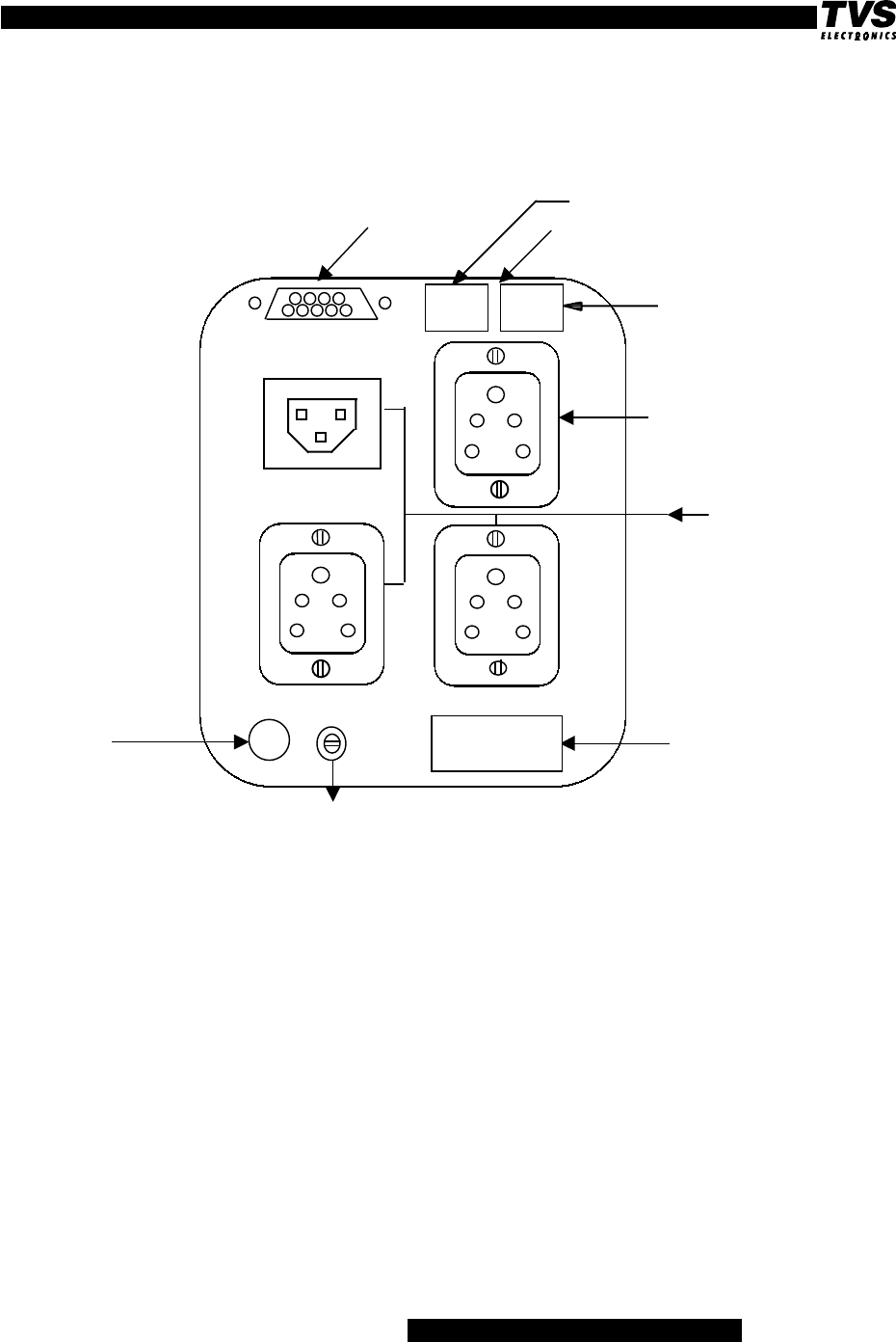
3.2 Rear Panel
Input Rating Label
Power cable
Resettable fuse
Fuse thermal 5A.
UPS output
with Power back-up
UPS output without Power
back-up
DB 9 port LAN/FAX/MODEM surge protect
StartUPS LITE
Fuse used is a resettable 5A. Reset the fuse in case it is open.
From Telephone line
To modem
IN
OUT
(Serial port)

User Manual Power UPS 500 Page 10
4.3 Connect to Utility
Plug the UPS into a two-pole, three-wire, grounded receptacle only. Avoid using
extension cords and adapter plugs.(Ensure proper grounding if you are using extension
cords).
4.4 Connect the Loads
Plug the loads into the output connectors of the UPS. To use the UPS as a master on-off
switch, make sure that all of the loads are switched on.
4.5 Mains connection
UPS can be always connected to the mains, which will allow UPS batteries charging and this
will not damage the UPS. Even when the output is switched off, the input to the UPS should
be ON.
4.6 Charging the Battery
The UPS charges its battery whenever it is connected to utility power. For best results,
charge the battery for 8 hours before use. It is acceptable to use the UPS without first
charging the battery, but run time may be reduced.
4.7 RJ 45 Connection
Connect the telephone line to RJ 45 connector of UPS-IN and UPS-OUT RJ 45 is connected
to the modem input. It protects from Lightning surges.
CAUTION:
1. The UPS output can be used only for electronic loads such as computers and telecom
munications equipment. Please donot connect laser printer to the power backed up
output. It can be connected to the surge protected socket.
A laser printer periodically
draws significantly more power than when idle, and will overload the UPS
2. Please ensure more than 5% of the rated total load is connected.
4. Installation
4.1 Inspection
Inspect the UPS upon receipt. Notify the carrier and dealer if there is damage. The
packaging is recyclable; save it for re-use or dispose of it properly.
4.2 Placement
Install the UPS in a protected area with adequate air flow and free of excessive dust.
Do not operate the UPS if the temperature and humidity are not within the specified limits.
In colder territories allow the UPS to come to room temperature before operating.

User Manual Power UPS 500 Page 11
5. Operation
5.1 To reset the UPS microprocessor, in case of an unknown situation:
With the UPS unplugged from the wall outlet, press the OFF button for 2 sec. This will
reset the internal microprocessor.
5.2 Turn off UPS Output Power
To turn off the UPS’s output power, press the OFF button longer than 2 sec.
5.3 Turn on UPS Output Power
Press the ON button 2 sec to switch the UPS on and to supply power to the loads.
NOTE:
The UPS is always on (CPU is operating) whenever it is plugged in and mains is
present. Even when the UPS is off it maintains the battery and will respond to commands
received through the computer interface port.
5.4 UPS Self-test
Use the self-test to verify both the operation of the UPS and the condition of the battery.
With the UPS plugged in to normal mains voltage, activate the self-test by pressing the
ON button.
5.5 Auto Voltage Regulation
The UPS automatically corrects high and low utility voltages so that the loads receive
voltage within the normal range.
5.6 DC (Cold) Start
When the UPS is off and there is no utility power, use the cold start feature to apply power
to the loads from the UPS‘s battery. Press the ON button until the red BAT-Led illumi-
nates. Release the button when the loads are powered within 4 seconds.
5.7 Shutdown Mode on 500VA model
In the shutdown mode the UPS stops supplying power to the load, waiting for the return of
mains voltage. If there is no mains voltage present, external devices (e.g. servers) con-
nected to the computer interface can command the UPS to shut down. This is normally
done to preserve battery capacity after the controlled shutdown of protected servers. The
UPS will flash the front panel BAT LED in shutdown mode.

User Manual Power UPS 500 Page 12
6. Alarms
6.1 On Battery
During on-battery operation, the on-BAT Led comes on and the UPS gives an audible
alarm consisting of one beep every 4 seconds. The alarm stops when the UPS returns to
on-line operation.
Press the ON button during on-battery operation to stop the beeping. This mutes the
current alarm only, the next on-battery alarm will be audible. Shutting off the audible
alarm in this way does not affect the computer interface alarm.
6.2 Overload
When the UPS is overloaded (when the connected loads exceed maximum load) the UPS
gives a continuous audible alarm (beep). The alarm remains on until the overload is
removed. Disconnect nonessential load equipment from the UPS to eliminate the over-
load.
6.3 Weak Battery
The UPS beeps for 1x30 Sec. and the BAT Led flashes every 30 seconds, if the battery
fails the self-test. The UPS repeats the alarm every 30 sec. Perform the self-test proce-
dure again to confirm the replace battery condition. The alarm stops when the battery
passes the self-test.

User Manual Power UPS 500 Page 13
7. Specifications
Input frequency : 50 ±5 Hz
Input voltage window : 140-300V AC
Output frequency : 50Hz ± 0.1 Hz in battery mode
Output voltage mains mode : 190-255V
Output voltage inverter mode : 230V±5% output load variation of 0-100%
Wave form : Quasi sine wave
Transfer time : 4msec typical
Power factor : 0.6
Battery type : Maintenance-free lead acid (12V-7Ah)
Recharge time : 8 hours typical from total discharge (UPS may
be used immediately after discharge, but will
Provide shorter backup time.
Temperature : -10 to 40 °C: operating
-20 to 55 °C: transport/storage for limited time
Relative humidity : 0 to 95%, non-condensing
Mechanical:
ledoM)mmnidxwxh(noisnemiD )gk(thgieW
ssorGteN
ETILSPUrewoP
AV005
592x301x05185.7

User Manual Power UPS 500 Page 14
8. On-Battery Run Time Table
Typical battery backup time:
run time (in minutes) as a function of load
After ‘End Autonomy’ automatic restart possible during 8 hours. After 8 hours restart must
be done manually: press button ‘ON’
sttaW/AVdaoLemitpukcaB
)%57(daolSPUlacipyT7
06/00133
081/00301
003/0055.4

User Manual Power UPS 500 Page 15
melborPesuaCelbissoPnoituloS
nruttonlliwSPU
.no
nonruttonlliwSPU
DELTABdnA
sehsalf
tonsawnottubNOehT
desserp
otnottubNOehtsserP
ehtdnaSPUehtrewop
daol
esuftiucrictupniSPU
nepo
ehtnodaolehtecudeR
gniggulpnuybSPU
ecalperdnatnempiuqe
ehtfoenoybesufeht
gnitardnaepytemas
demmargorpnisiSPU
edomnwod-tuhs noitautislamroN
nruttonlliwSPU
.FFOroNO ecafretniretupmoC
melborp
retupmocehttcennocsiD
wonSPUehtfI.ecafretni
ehtkcehC.yllamronskrow
ehtdnaelbacecafretni
.retupmocdehecatta
nurttonnacSPU
dnaDELTABNO
eraDELENIL
.gnihsalf
noitarugifnocerawtfoS
rorre
,sniamehttcennocsiD
4rofnottubFFOehtsserp
teserlliwsihT.sdnoces
.rossecorplanretnieht
nosetarepoSPU
neveyrettab
egatlovenilhguoht
.stsixe
detrotsidrowol,hgihyreV
egatlovenil
siegatlovtupniehtfitseT
ootsahrowolrohgihoot
.noitrotsidhcum
speebSPU
.yllanoisacco
,noitarepoSPUlamroN
egatlovsniamontub
tneserp
siSPUehT.enoN
.daolehtgnitcetorp
9. Trouble shooting

User Manual Power UPS 500 Page 16
melborPesuaCelbissoPnoituloS
sahrezzubSPU
dna,enottnatsnoc
siegatlovsniam
tneserp
dedaolrevoSPU evissecxeehtevomeR
daol
sahrezzubSPU
dna,enottnatsnoc
siegatlovsniam
tneserpton
trohsrodedaolrevoSPU
edomyrettabnitiucric
rewopsniamevomeR
rofnottub’FFO’hsuPdroc
.ces2
tonseodSPU
detcepxeedivorp
emitpukcab
kaewsiyrettabs’SPUehT
dnaegatuotneceroteud
roemitegrahcertrohsa
gnidnesiemit-efilsti
ehT.yrettabehtegrahC
seriuqeryrettabs’SPU
naretfagnigrahcer
seirettaB.egatuodenetxe
yehtnehwretsaftuoraew
ro/dnanetfodesuera
hgihtadetareponehw
ehtfI.serutarepmet
fodneehtraensiyrettab
ehtdnaefilecivressti
siemitpukcab
redisnoc,tneiciffusni
neveyrettabehtgnicalper
yrettabecalperehtfi
evitcateytonsirotacidni
wolyrettaBehT
sehsalfdeL
yrettabkaeW
otyrettabehtwollA
nettsaeltarofegrahcer
melborpehtfI.sruoh
,gnigrahcerretfastsisrep
.yrettabehtecalper

User Manual Power UPS 500 Page 17
10 About the Battery
1. Life of the battery depends on operating temperature and on the number of discharge
cycles.
2. “WHEN DOES THE BATTERY NEED REPLACING?”
If the BAT Led on the front of the UPS flashes 1x30sec and buzzer sounds, it implies that the
battery will no longer hold a full charge. Under this circumstances, if a power failure occurs,
the UPS runs less than half its normal length of time when compared to a good battery.
Perform the following steps to make sure the battery needs replacing:
1) make sure the UPS is plugged into a live wall outlet
2) charge the UPS for at least 8 hours
3) turn the UPS off and then back on
4) press ON switch to force a self-test
After step 4, if the BAT Led still flashes, there might be something wrong with the battery.
Since the battery will eventually wear out and needs to be replaced, please contact your
local dealer and ask for the battery replacement services
3. Extendability of battery is not possible in this UPS. Please do not add external battery to
the UPS. This will void the Warranty.

User Manual Power UPS 500 Page 18
12 Storage
Store the UPS covered and placed upright in a cool place, with its battery fully charged.
Before storing charge the batteries for at least 24 hours. Disconnect any cables con-
nected to the computer interface port to avoid unnecessarily draining the battery.
Make sure that the UPS is switched off.
Storing the unit for longer than 3 months can reduce the life of the batteries. To
maintain the normal life expectancy, recharge the battery. For chargeing the battery refer
section 4.7.
13 Communications Port
The UPS to send information concerning power levels and UPS condition to the computer
The Software can monitor the following.
1. Mains Input voltage
2. Mains Input frequency
3. UPS Output voltage
4. UPS Output frequency
5. UPS Load %
6. Battery voltage
7. Backup time
8. Alarms
In the event of batteries near exhaustion, the UPS can send commands for unattended
controlled shutdown of computer systems. UPS can also receive shutdown command
from the computer. All these functions can be realised using host software such as “Safeware”/
”Rakshak” available from TVSE.
Safeware can be installed in IBM PC compatible and works in Windows platform. The
safeware can be down loaded from www.tvse.com
UPS should be connected to the host only through cables supplied by TVS-E. In the cable,the
label indicates which side requires to be connected to the UPS and which one to the PC.The
cable should be connected to the UPS DB9 port and PC comport.
Caution: Do not use any other serial interface cable, other than the one supplied along with the
UPS.

User Manual Power UPS 500 Page 19
SafeWare Program:
Each time the Windows 95 program is started , SafeWare for windows 95 will
automatically start and run unless the user deletes the SafeWare Icon from the Windows
95 Startup folder. By default, SafeWare will start in “Minimized” mode.
Once the SafeWare application has been closed, clicking on the SafeWare icon in
either the SafeWare folder or the Startup folder will once again start SafeWare.
Main SafeWare Screen
The safeWare screen makes a variety of AI-UPS status and control information available
to the user. The left portion of the SafeWare screen displays six large gauges that are
labeled:
Input Voltage Output voltage
Input Frequency Output Frequency
Battery Level Load Level.
These gauges are similar in appearance to automative gauges and graphically indicate
the current values of the specific labeled AI-UPS categories. A text box below each
gauge also shows the exact value or percentage of the specific category.
The top right hand portion of the SafeWare screen has indicators for the input power and
AI-UPS status. The indicators will turn on, off or flash to indicate the current input Power
and AI-UPS condition. they include:
Power Normal Battery Low UPS Fault
Power Failure Battery Weak UPS Overload
Just below the Power and AI-UPS Status indicators is the Countdown Time display box.
This box will indicate the countdown time that has been entered by the user in the
SafeWare Settings. In case of a loss of utility power, the value in the box will decrease
until it reaches zero at which time SafeWare will cause the Windows 95 save/exit routine
to begin. At any time during the countdown, the user may click on the box to the left of
the Abort Countdown box at which time the countdown will resume, or 2) the AI-UPS
reaches a battery low condition. If a battery low condition occurs, SafeWare will override
the abort command and automatically run the Windows 95 safe/exit routine and cause
the computer system and AI-UPS to shutdown.
The lower right hand portion of the SafeWare screen displays the Waveform chart which
is a graphical waveform representation of the AI-UPS operational parameters. there are
three AI-UPS categories that can be displayed on the Waveform chart:Input/Output
Voltage Waveform, Input/Output Frequency Waveform, and Battery/Load Level Wave-
form. By clicking on the Toggle Waveform button user can display the different wave-
forms.
The Waveform chart displays information in a time based format. Time markings below
the chart will inform the user of the time that a power event occurred. Buttons to the right

User Manual Power UPS 500 Page 20
of the chart can be used to view different time periods. They include:Current View, Previ-
ous View, Previous Page, Next Page, Scan Left and Scan right. The waveform informa-
tion can be viewed at any time and will continue to be updated as long as SafeWare is
running. however, if the user terminates the SafeWare program, all waveform information
will be erased unless the user has recorded the information using the Recode button
located under the Toggle Waveform button. If the waveform information is recorded, it is
saved in a DAT file that can later be accessed and viewed using the SafeWare
UPSWave program in the SafeWare folder. The Min/Max levels of the selected waveform
are also shown in boxes under the chart.
The SafeWare screen also has several elements that the user can use to facilitate AI-
UPS operation, control and diagnosis:
Menu Bat - Allows access to File, Diagnostic, Option, View, and Help topics.
Toolbar- Allows direct access to all diagnostic and Option topics without using the
Menu
Status Bar- Displays current date, time and Next scheduled shutdown information.

User Manual Power UPS 500 Page 21
13. Frequently asked questions:
Q:What is the warranty of the UPS?
A: One year on the Battery, Three years on the unit, against registration of the unit.
Q:Where can I get UPS serviced?
A:UPS required to be carry-in to the nearest TVS-E Authorised Service Provider for
serviceing.
Q:What is the life of the battery?
A:Battery life is 3-5 years depending on the usuage.It depends on the operating tem-
perature and number of discharge cycles.
Q:What is the use of cyber jack?
A:Protects Modem/Telephone/Network nodes from lighting (High voltage)surges.
Q:Can an any RS232 cable be connected?
A:You are required to connect the TVS-E supplied RS232 cable
Q:Can a laser printer be connected to the backed up socket?
A:No. You are required to coneected to the surge protected socket.
Q:Can I keep the mains input switch always ON?
A:Yes. You can keep the input switch always ON. This will enable the UPS to charge the
battery if required. More ever if the mains fails the UPS will automatically shut down.
Q:How much time the battery needs to be charged?
A:It depends on the charge level of the battery. If it is fully discharged, it required around
6 hours to charge to 90% level.
Q:What is no load shutdown?
A:Conditions for no load shutdown.
a) Less than 5% of the rated load.
b) No mains available.
Then UPS will shutdown itself, there by protecting the battery life.

User Manual Power UPS 500 Page 22
How to get Service
As soon as the installation is completed, you are requested to fill up the Warranty Registration
Card. to get your name registered with us. To avail warranty service, please contact the nearest
TVS-E Authorised Dealer/Authorised service centre/Regional office. While registering your call,
please mention/produce (a) Serial no. of the unit (b) date of purchase as mentioned in the invoice of
the product. (c) The problem you are facing with the unit d) Your Tel. no./FAX no./Postal Address/
E-mail address for contact (e) Model name of the product.
Limitation of Implied Warranties.
THERE ARE NO WARRANTIES, EXPRESSED OR IMPLIED, WHICH EXTEND BEYOND
THE DESCRIPTION CONTAINED HEREIN INCLUDING THE IMPLIED WARRANTY OF MER-
CHANTABILITY AND FITNESS FOR A PARTICULAR PURPOSE.
Exclusion of Damages
Our liability is limited to the cost of repair or replacement of the product. Wherein TVSE may use
reconditioned parts/units or new parts/units. We shall not be liable for:
1. Damage to other products caused by any defects in the product, damages based upon
inconvenience, loss of business opportunity, loss of goodwill, loss of data, loss of software, cost of
substitute equipment, interference with business relationship, claims by third parties or other com-
mercial loss, even if advised of the possibility of such damages.
2. Any other damages whether incidental, consequential or otherwise.
3. Any claim against the customer by any other party.
Life support
We do not recommend the use of our UPS products for life support equipment or direct care
where failure of UPS product could cause failure of or diminished effectiveness of the life support
equipment or the patient care.
Information on this manual is subject to change without notice. This product could include
technical inaccuracies or typographical errors. Changes are periodically made to the information
herein. These changes may be included in the new editions of this product.
TVS ELECTRONICS LIMITED
Plot No.34. Developed plots, South phase, Industrial estate
Guindy Chennai-600 032.
Visit us at www.tvse.com
Copyright & Regulatory Information
This manual and software described in it are copyrighted with all rights reserved. This manual may
not be copied, in whole or in part, without written consent. All product names are trademarks and or
registered trademarks of their respective companies.
FCC Statement
This equipment has been tested and found to comply with the limits for a Class B digital device,
pursuant to Part 15 of the FCC Rules. These limits are designed to provide reasonable protection
against harmful interference in a residential installation. This equipment generates, uses and can
radiate radio frequency energy and, if not installed and used in accordance with the instructions,
may cause harmful interference to radio communications. However, there is no guarantee that
interference will not occur in a particular installation. If this equipment does cause harmful
interference to radio or television reception, which can be determined by turning the equipment off
and on, the user is encouraged to try to correct the interference by one or more of the following
measure:
- Reorient or relocated the receiving antenna.
- Increase the separation between the equipment and receiver.
- Connect the equipment into a different outlet circuit from than the receiver.
- Consult an experienced radio/TV technician for help.
CAUTION: Any changes of modifications not expressly approved by the grantee of this
device could void the users authority to operate the equipment.