TYCOFETY KANTECH 12SA550 Stand-Alone Door Controller with I/O Relay Module User Manual ioPass
TYCO SAFETY PRODUCTS / KANTECH Stand-Alone Door Controller with I/O Relay Module ioPass
UserManual.wiki
>
TYCOFETY KANTECH
>
12SA550 User Manual
user manual
Navigation menu
Upload a User Manual
Namespaces
Wiki Guide
HTML
PDF
Info
Views
User Manual
Discussion / Help
Navigation


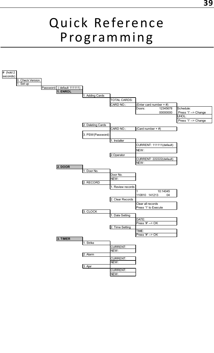
![10Prog ramming IoPas s™ - Introduct ionIoPass Programming ModeTo enter the programming mode:1- Hold the # key for two seconds.2- Press 1. SET UP.3- Enter the 6-digit password followed by the [#] key. The default password is [111111].The LCD will display the following information:1. ENROL 2. DOOR3. TIMER 4. SYSTEMFrom these basic functions, more options are available.When programming the unit, you need to know that:• The [*] key is used to either go back to the previous menu, or delete what was entered.• The [#] key is used to accept, save the data that was modified or programmed in the system and quit.](https://usermanual.wiki/TYCOFETY-KANTECH/12SA550/User-Guide-2011110-Page-22.png)
![12Four Access Schedules DefaultAccess Schedule 1Interval SUN MON TUE WED THU FRI SAT[1] 00:00 - 24:00[2] 00:00 - 00:00[3] 00:00 - 00:00[4] 00:00 - 00:00Access Schedule 2Interval SUN MON TUE WED THU FRI SAT[1] 00:00 - 00:00[2] 00:00 - 00:00[3] 00:00 - 00:00[4] 00:00 - 00:00Access Schedule 3Interval SUN MON TUE WED THU FRI SAT[1] 00:00 - 00:00[2] 00:00 - 00:00[3] 00:00 - 00:00[4] 00:00 - 00:00Access Schedule 4Interval SUN MON TUE WED THU FRI SAT[1] 00:00 - 00:00[2] 00:00 - 00:00[3] 00:00 - 00:00[4] 00:00 - 00:00](https://usermanual.wiki/TYCOFETY-KANTECH/12SA550/User-Guide-2011110-Page-24.png)
![13Unlocked Schedule DefaultUnlock ScheduleInterval SUN MON TUE WED THU FRI SAT[1] 00:00 - 24:00[2] 00:00 - 00:00[3] 00:00 - 00:00[4] 00:00 - 00:00](https://usermanual.wiki/TYCOFETY-KANTECH/12SA550/User-Guide-2011110-Page-25.png)

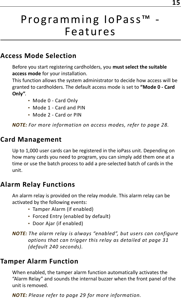
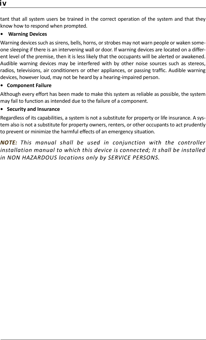
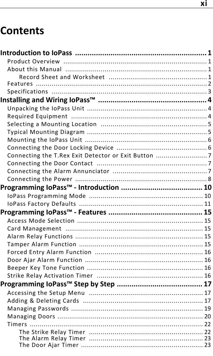
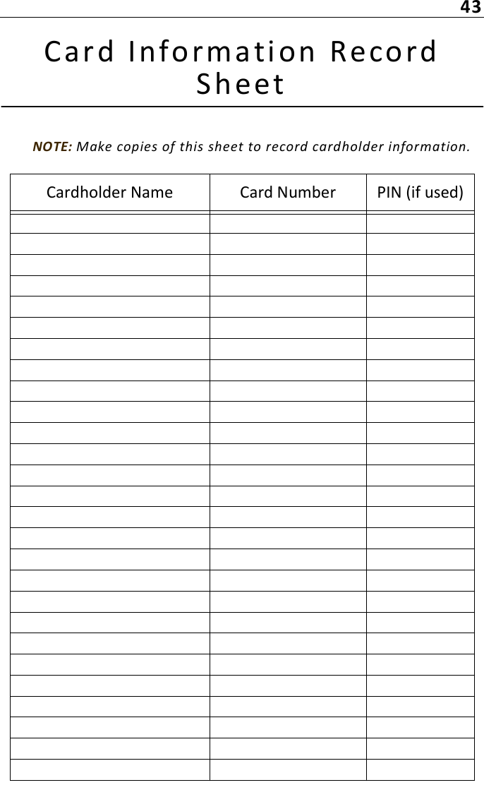
![17Prog ramming IoPas s™ Step by S tepAccessing the Setup MenuTo access the setup menu, hold the [#] key for 2 seconds then press ‘1’.NOTE: The operator password allows programing all the settings EXCEPT changing the installer password and updating the firmware.Adding & Deleting CardsNOTE: Once you have selected the “Access Mode”, you may start enrolling cards. Otherwise, please refer to "Access Mode Selection" on page 15.Use the provided "Card Information Record Sheet" on page 43 to store user information (card number, name and PIN if applicable). Also, if you are using the PIN feature, you may want to gather the PIN from cardholders in advance.All new cards must be enrolled into the unit before access is allowed. Up to 1,000 cards can be stored in the unit. Cards are stored based on their programming sequence within the unit. If a card that is not enrolled is presented to the reader, the INVALID CARD message is displayed. NOTE: Depending on how many cards you need to program, you can simply add them one at a time or use the batch process to add a pre-selected batch of cards in the unit.If the maximum number of cards has been reached, the NO SPACE message will be displayed each time you attempt to add a new card.To add a card:1- Enter the master password (default is [111111]) followed by the [#] key. The LCD displays the following:1. ENROL 2. DOOR3. TIMER 4. SYSTEM](https://usermanual.wiki/TYCOFETY-KANTECH/12SA550/User-Guide-2011110-Page-29.png)
![182- Press [1-Enrol]. The LCD displays:1-Adding cards2-Deleting 3-PSW3- Press [1-Adding cards]. The LCD displays:TOTAL CARDS: XX (xx=# of cards in unit)CARD NO.__:______4- There are two ways to enter the card number in the system:• You can simply present the card to the reader and the number will automatically be entered.• You can type in the number (XX:XXXXX) printed on the card followed by the [#] sign using the keypad. If you need to enter special characters (hexadecimal) see page 19.5- Once you have entered the card number, you will see the following screen:Doors: 12345678000000006- Enter 1 (valid) or 0 (not valid) below each door number to indicate for which door the entered card number is valid or not. 7- To validate your choices, press #.8- To change the schedule associated to the selected card, press 1. Pressing 1 repeatedly will scroll through each schedule number.9- To enable the UHOL (Unlock on Holiday) function, press 1 to display Yes. Otherwise, the doors will stay locked on all holidays.10- Enter another card number or press # to exit the programming mode.To delete a card:1- Enter the master password (default is [111111]) followed by the [#] key. The LCD displays the following:1. ENROL 2. DOOR3. TIMER 4. SYSTEM2- Press [1-Enrol]. The LCD displays:1-Adding cards2-Deleting 3-PSW3- Press [2-Deleting]. The LCD displays:TOTAL CARDS: XX (xx=# of cards in unit)CARD NO.__:______4- There are two ways to enter the card number in the system:](https://usermanual.wiki/TYCOFETY-KANTECH/12SA550/User-Guide-2011110-Page-30.png)
![19• You can simply present the card to the reader and the number will automatically be entered.• You can type in the number (XX:XXXXX) printed on the card followed by the [#] sign using the keypad. If you need to enter special characters (hexadecimal) see page 19.5- To validate your choices, press #.6- Enter another card number to delete or press # to exit the programming mode.Managing PasswordsTo modify the passwords:1- Enter the password (default is [111111]), then [#].2- The LCD displays the following:1. ENROL 2. DOOR3. TIMER 4. SYSTEM3- Press [1-ENROL]. The LCD displays the following:1-Adding cards2-Deleting 3-PSW4- Press [3-PSW]. The LCD displays:1. Installer2. OperatorSpecial Characters (Hexadecimal)When inputting the card number using the keypad, you may need to program special characters. You can do this using hexadecimal digits. The following hexadecimal digits will insert special characters into the card number. To program a hexadecimal digit press [*], then press the number corresponding to the hexadecimal digit.If another hexadecimal digit is required, press [*] again, then press the corresponding number. The ioPass reader will return to decimal programming on the next digit.Example: To program “4E”, you would enter:• [4] - programs a “4”• [*][5] - programs an “E”](https://usermanual.wiki/TYCOFETY-KANTECH/12SA550/User-Guide-2011110-Page-31.png)
![205- Select the password to be changed (Installer or Operator). The LCD displays:Current: 111111 New:6- Enter the new password. This password must be 6 characters. 7- Press [#] to save and exit.Managing Doors To select a door:1- Enter the password (default is [111111]), then [#].2- The LCD displays the following:1. ENROL 2. DOOR3. TIMER 4. SYSTEM3- Press [2-DOOR]. The LCD displays the following:1. Door No2. RECORD 3. CLOCK4- Press [1-Door No]. The LCD displays:Door No. XXNEW:5- Enter a new door number. This number must be from 1 to 8. 6- Press [#] to save and exit.To review a door records:1- Enter the password (default is [111111]), then [#].2- The LCD displays the following:1. ENROL 2. DOOR3. TIMER 4. SYSTEM3- Press [2-DOOR]. The LCD displays the following:1. Door No2. RECORD 3. CLOCK4- Press [2-RECORD]. The LCD displays (for example):Transaction # Card #Date(YYMMDD) Time (hh:mm:ss) Door #5- Press [#] to save and exit or [*] to go back to the previous menu.](https://usermanual.wiki/TYCOFETY-KANTECH/12SA550/User-Guide-2011110-Page-32.png)
![21To clear a door records:1- Enter the password (default is [111111]), then [#].2- The LCD displays the following:1. ENROL 2. DOOR3. TIMER 4. SYSTEM3- Press [2-DOOR]. The LCD displays the following:1. Door No2. RECORD 3. CLOCK4- Press [2-RECORD]. The LCD displays:1. Review records2. Clear records5- Press [2-Clear records]. The LCD displays:Clear all recordPress ‘1’ to ExecuteTo set the date:1- Enter the password (default is [111111]), then [#].2- The LCD displays the following:1. ENROL 2. DOOR3. TIMER 4. SYSTEM3- Press [2-DOOR]. The LCD displays the following:1. Door No2. RECORD 3. CLOCK4- Press [3-CLOCK]. The LCD displays:1. Date setting2. Time setting5- Press [1-Date setting]. The LCD displays:Date: 2012/11/21Press ‘#’ -> OK6- Press [#] to exit.To set the time:1- Enter the password (default is [111111]), then [#].2- The LCD displays the following:1. ENROL 2. DOOR3. TIMER 4. SYSTEM](https://usermanual.wiki/TYCOFETY-KANTECH/12SA550/User-Guide-2011110-Page-33.png)
![223- Press [2-DOOR]. The LCD displays the following:1. Door No2. RECORD 3. CLOCK4- Press [3-CLOCK]. The LCD displays:1. Date setting2. Time setting5- Press [2-Time setting]. The LCD displays:Time: 11:39Press ‘#’ -> OK6- Press [#] to exit.TimersThe Strike Relay Timer By default, the locking device relay is pre-set to 10 seconds, meaning that the door will remain unlocked for that period of time following an “access granted” event. The timer can be modified from 1-255 seconds.To set the strike relay timer:1- Enter the master password (default is [111111]) followed by the [#] key. The LCD displays the following:1. ENROL 2. DOOR3. TIMER 4. SYSTEM2- Press [3-TIMER]. The LCD displays:1.Strike 2.Alarm3.Ajar3- Press [1-Strike]. The LCD displays:CURRENT: 10 SEC.NEW:4- Using the keypad, enter the number of seconds during which the locking device will be unlocked. Enter digits in “seconds”. 5- Press [#] to save.6- Press [#] again to exit.](https://usermanual.wiki/TYCOFETY-KANTECH/12SA550/User-Guide-2011110-Page-34.png)
![23The Alarm Relay TimerBy default, the alarm relay is pre-set to 240 seconds, meaning that the connected annunciator will remain activated for that period of time. The timer can be modified from 1-255 seconds.The alarm relay can be activated by the following events:• Tamper alarm (if enabled);• Forced entry (enabled by default);• Door ajar (if enabled);NOTE: This relay is always “enabled”, but options that can trigger this relay can be customized by the user.To configure the alarm relay timer:1- Enter the master password (default is [111111]) followed by the [#] key. The LCD displays the following:1. ENROL 2. DOOR3. TIMER 4. SYSTEM2- Press [3-TIMER]. The LCD displays:1.Strike 2.Alarm3.Ajar3- Press [2-Alarm]. The LCD displays:CURRENT: 240 SEC.NEW:4- Using the keypad, enter the number of seconds during which the alarm will sound. Enter digits in “seconds”. 5- Press [#] to save.6- Press [#] again to exit.The Door Ajar TimerThe door ajar timer is set to 30 seconds. If the door remains open longer than 30 seconds, after an “access” event, an alarm will sound until the door is closed correctly. If required, you can modify this setting and program a value between 1-255 seconds.To set the door ajar timer:1- Enter the master password (default is [111111]) followed by the [#] key. The LCD displays the following:1. ENROL 2. DOOR3. TIMER 4. SYSTEM](https://usermanual.wiki/TYCOFETY-KANTECH/12SA550/User-Guide-2011110-Page-35.png)
![242- Press [3-TIMER]. The LCD displays:1.Strike 2.Alarm3.Ajar3- Press [3-Ajar]. The LCD displays:CURRENT: 30 SEC. NEW:4- Using the keypad, enter the number of seconds during which the alarm will sound. Enter digits in “seconds”. 5- Press [#] to save.6- Press [#] again to exit.Using the Door Ajar FunctionDepending on whether the door ajar function is configured to trigger the alarm relay, follow this procedure to STOP the warning device.1- When the door is left open, the alarm relay will be triggered OR the unit’s piezo will sound. The LCD will display:READY FOR CARDDOOR OPEN2- The “Door Open” message is displayed (and blinking) and will remain on the LCD until the door is closed properly.Configuring the Tamper Alarm Function This tamper alarm will activate the alarm relay when the front cover of the ioPass unit is removed.Recommended Configuration Procedure• Enable tamper function;• Modify alarm relay timer activation (if required). See page 31 for more information.Enabling the Tamper Alarm Function1- To enter the programming mode, enter the master password (default is [111111]) followed by the [#] key. The LCD displays the following:1. ENROL 2. DOOR3. TIMER 4. SYSTEM](https://usermanual.wiki/TYCOFETY-KANTECH/12SA550/User-Guide-2011110-Page-36.png)
![252- Press [4-SYSTEM]. The LCD displays:1.ALARM 2.MODE3.OTHER 4.IN/OUT3- Press [1-ALARM]. The LCD displays:1.Tamper 2.Force3.AJAR4- Press [1-Tamper]. The LCD displays:CURRENT: DISABLEPress ’1’ --> Change5- Press [1] until desired mode is displayed. Pressing this key will toggle between selections. 6- Press [#] to save and exit.Using the Tamper Alarm FunctionOnce the function is enabled in the system, follow this procedure to STOP the tamper alarm if it has been activated.1- When the tamper alarm has been activated, the alarm relay will be triggered (usually an annunciator) and the LCD will display:READY FOR CARDTAMPER ALARM (blink)2- This “Tamper Alarm” message is displayed (and blinking) and will remain on the LCD until an “access granted” operation is processed by the unit;3- Present your card and enter your PIN or master password (depending on the system set up), access will be granted and the message will disappear.Configuring the Forced Entry Alarm This function, already enabled in the unit (default), will automatically activate the “Alarm Relay” when the door contact detects unauthorized access (without card or password or both) or a “door forced open” type of event.Recommended Configuration Procedure• Since this function is already enabled in the unit, follow the procedure below if you need to disable it (not recommended);](https://usermanual.wiki/TYCOFETY-KANTECH/12SA550/User-Guide-2011110-Page-37.png)
![26• Modify alarm relay timer activation (if required). See page 31 for more information.Enabling/Disabling the Force Entry Alarm Function1- To enter the programming mode, enter the master password (default is [111111]) followed by the [#] key. The LCD displays the following:1. ENROL 2. DOOR3. TIMER 4. SYSTEM2- Press [4-SYSTEM]. The LCD displays:1.ALARM 2.MODE3.OTHER 4.IN/OUT3- Press [1-ALARM]. The LCD displays:1.Tamper2.Force3.AJAR4- Press [2-Force]. The LCD displays:CURRENT: ENABLEPress ’1’ --> Change5- Press [1] until desired mode is displayed. Pressing this key will toggle between selections. 6- Press [#] to save and exit. Using the Force Entry FunctionFollow this procedure to STOP the force entry alarm if it has been activated.1- When the force entry has been activated, the alarm relay will be triggered (usually an annunciator) and the LCD will display:READY FOR CARD FORCE ENTRY2- This “Force Entry” message is displayed (and blinking) and will remain on the LCD until an “access granted” operation is processed by the unit;3- Present your card and enter your PIN or master password (depending on the system set up), access will be granted and the message will disappear.](https://usermanual.wiki/TYCOFETY-KANTECH/12SA550/User-Guide-2011110-Page-38.png)
![27Configuring the Door Ajar Function This function, already enabled in the unit (default), can activate the “Alarm relay” when the door is opened longer than the pre-set time following an access granted operation.By default, the ioPass warning device will sound until the door is closed correctly. The user can decide if the alarm relay needs to be activated when this situation occurs. Enabling/Disabling the Door Ajar Function1- Enter the master password (default is [111111]) followed by the [#] key. The LCD displays the following:1. ENROL 2. DOOR3. TIMER 4. SYSTEM2- Press [4-SYSTEM]. The LCD displays:1.ALARM 2.MODE3.OTHER 4.IN/OUT3- Press [1-ALARM]. The LCD displays:1.Tamper 2.Force3.AJAR4- Press [3-AJAR]. The LCD displays:1.Ajar alarm2.Ajar relay5- Press [1-Ajar alarm] to enable or disable the door ajar function. The LCD displays:CURRENT: ENABLEPress ’1’ --> Change6- Press [1] until desired mode is displayed. Pressing this key will toggle between selections. 7- Press [#] to save and exit. If you want the alarm relay to be activated when a “door ajar” situation occurs, follow the procedure below.](https://usermanual.wiki/TYCOFETY-KANTECH/12SA550/User-Guide-2011110-Page-39.png)
![28Activating the Alarm Relay on Door Ajar1- Enter the master password (default is [111111]) followed by the [#] key. The LCD displays the following:1. ENROL 2. DOOR3. TIMER 4. SYSTEM2- Press [4-SYSTEM]. The LCD displays:1.ALARM 2.MODE3.OTHER 4.IN/OUT3- Press [1-ALARM]. The LCD displays:1.Tamper2.Force3.AJAR4- Press [3-AJAR]. The LCD displays:1.Ajar alarm2.Ajar relay5- Press [2-Ajar relay] to enable (trigger) or disable (not trigger) the alarm relay when the door is left open longer than pre-set time. The LCD displays:CURRENT: DISABLEPress ’1’ --> Change6- Press [1] until desired mode is displayed. Pressing this key will toggle between selections. 7- Press [#] to save and exit.Selecting the Access Mode The access mode is the most important function of the system. Three (3) access modes are available in the system:• Mode “0” - Card Only - DEFAULT: This mode only requires users to present their card to be granted access.• Mode “1” - Card and PIN: This mode requires that users present their card and then enters their PIN on the keypad. Make sure the keypad can be accessed by cardholders if you are using this mode.• Mode “2” - Card or PIN: This mode will require that users present their card to the reader to be granted access OR enter their PIN.](https://usermanual.wiki/TYCOFETY-KANTECH/12SA550/User-Guide-2011110-Page-40.png)
![29To Select an Access Mode:1- Enter the password (default is [111111]), [#].NOTE: It is strongly recommended to modify the default password before programming the unit. To modify the master password, refer to "Managing Passwords" on page 19.2- The LCD displays the following:1. ENROL 2. DOOR3. TIMER 4. SYSTEM3- Press [4-SYSTEM]. The LCD displays:1.ALARM 2.MODE3.OTHER 4.IN/OUT4- Press [2-MODE]. The LCD displays:1.Access 2.Tone3.DI 4. First man5- Select [1-Access]. The LCD displays:MODE: Card onlyPRESS ’1’ --] CHANGE6- Press [1] until desired mode is displayed. Pressing this key will toggle between selections;7- When the required mode is displayed (Card only, Card + PIN, Card or PIN), press [#] to save and exit.Beeper Key Tone ConfigurationThis function, already enabled in the unit (default), provides an audible “beep” tone when the keys of the keypad are used. This function is convenient when the cardholder must key in his PIN.To disable the beeper:1- Enter the master password (default is [111111]) followed by the [#] key. The LCD displays the following:1. ENROL 2. DOOR3. TIMER 4. SYSTEM2- Press [4-SYSTEM]. The LCD displays:1.ALARM 2.MODE3.OTHER 4.IN/OUT](https://usermanual.wiki/TYCOFETY-KANTECH/12SA550/User-Guide-2011110-Page-41.png)
![303- Press [2-MODE]. The LCD displays:1.Access 2.Tone3.DI 4. First man4- Press [2-Tone]. The LCD displays:CURRENT: ENABLEPress ’1’ --> Change5- Press [1] until desired mode is displayed. Pressing this key will toggle between selections. When required mode is displayed, press [#] to save and exit.Door Input ConfigurationThe ioPass unit allows the installer to configure the exit button and the door contact. These “normally open” contacts can be modified to “normally closed” to suit the installer’s requirements.To configure the door input:1- Enter the master password (default is [111111]) followed by the [#] key. The LCD displays the following:1. ENROL 2. DOOR3. TIMER 4. SYSTEM2- Press [4-SYSTEM]. The LCD displays:1.ALARM 2.MODE3.OTHER 4.IN/OUT3- Press [2-MODE]. The LCD displays:1.Access 2.Tone3.DI 4. First man4- Press [3-DI]. The LCD displays:1.Exit button2.Door contact5- Press [1-Exit button] to modify the exit button polarity OR press [2-Door] to modify the door contact polarity. In either cases, the LCD displays:CURRENT: NCPress ’1’ --> Change6- Press [1] until desired mode is displayed. Pressing this key will toggle between selections. When required mode is displayed, press [#] to save and exit.](https://usermanual.wiki/TYCOFETY-KANTECH/12SA550/User-Guide-2011110-Page-42.png)
![31First Man ConfigurationThe ioPass unit allows the installer to configure the first man entry function. This way, the door schedule will be enable only once the first user with a valid card is granted access.To configure the first man access:1- Enter the master password (default is [111111]) followed by the [#] key. The LCD displays the following:1. ENROL 2. DOOR3. TIMER 4. SYSTEM2- Press [4-SYSTEM]. The LCD displays:1.ALARM 2.MODE3.OTHER 4.IN/OUT3- Press [2-MODE]. The LCD displays:1.Access 2.Tone3.DI 4. First man4- Press [3-First man]. The LCD displays:CURRENT: ENABLEPress ’1’ --> Change5- Press [1] until desired mode is displayed. Pressing this key will toggle between selections. When required mode is displayed, press [#] to save and exit.Schedules ConfigurationFrom this menu, you can configure access and unlock schedules. An access schedule defines the access times for users with cards. An unlock schedule defines the access times for the general public.To configure a schedule:1- Enter the master password (default is [111111]) followed by the [#] key. The LCD displays the following:1. ENROL 2. DOOR3. TIMER 4. SYSTEM2- Press [4-SYSTEM]. The LCD displays:1.ALARM 2.MODE3.OTHER 4.IN/OUT](https://usermanual.wiki/TYCOFETY-KANTECH/12SA550/User-Guide-2011110-Page-43.png)
![323- Press [3-OTHER]. The LCD displays:1.SCHEDULES2.HOLIDAYS 3. Language4- Press [1-SCHEDULES]. The LCD displays:1.Access schedule2.Unlock schedule5- Press [1-Access schedule], the LCD displays:SD I START END01 1 00:00 - 24:00or Press [2-Unlock schedule], the LCD displays:DN I START END01 1 00:00 - 24:00SD: Schedule number (up to 4 schedules).DN: Door Number (up to 8 doors).I: Interval number (up to 4 intervals).START: Time at which the schedule is valid.END: Time at which the schedule is no more valid.6- Use the up and down arrows to scroll between schedule numbers. 7- Press the right arrow to move to the interval. Use the up arrow to scroll between interval numbers. 8- Press the [#] key to move to the start time.9- Enter the start and end times using the keypad digits.10- Press the [#] key to go to the next menu. The LCD displays:DAYS S M T W T F S02 1 0 0 1 1 1 0 011- Enter 1 for each day the schedule is valid or 0 for each day the schedule is not valid.12- Press the [#] go back to the previous menu.13- Press the [#] to exit.](https://usermanual.wiki/TYCOFETY-KANTECH/12SA550/User-Guide-2011110-Page-44.png)
![33Holidays ConfigurationTo configure a holiday:1- Enter the master password (default is [111111]) followed by the [#] key. The LCD displays the following:1. ENROL 2. DOOR3. TIMER 4. SYSTEM2- Press [4-SYSTEM]. The LCD displays:1.ALARM 2.MODE3.OTHER 4.IN/OUT3- Press [3-OTHER]. The LCD displays:1.SCHEDULES2.HOLIDAYS 3. Language4- Press [2-HOLIDAYS]. The LCD displays:1.Recurring2.Non-recurring5- Press [1-Recurring], the LCD displays:HOL [DATE]01 January - 01or press [2-Non-recurring], the LCD displays:HOL [DATE]01 Month- 00HOL: Holiday number (up to 24 holidays).DATE: Month and day of the holiday.Recurring holidays: For those holidays that recur at the sameday of every year; once configured, they always remain valid.January 01 pre-set at Holiday 01 & December 25 pre-set atHoliday 21.Non-recurring holidays: For those holidays that are not fixedin relation to the calendar, for example Easter. Once config-ured, they are valid only once and will be automaticallycleared after December 31; therefore configuring non-recur-ring holidays each year is required if using this function.6- Use the up arrow to scroll between holiday numbers.](https://usermanual.wiki/TYCOFETY-KANTECH/12SA550/User-Guide-2011110-Page-45.png)
![347- Press the right arrow to move to the month selection. Use the up and down arrows to scroll between months. 8- Press the right arrow to move to the day. Use the up and down arrows to scroll between days of the month. 9- Press the [*] to go back to the previous menu. From there you can configure another holiday.10- Press the [#] to exit.Language ConfigurationTo change the user interface language:1- Enter the master password (default is [111111]) followed by the [#] key. The LCD displays the following:1. ENROL 2. DOOR3. TIMER 4. SYSTEM2- Press [4-SYSTEM]. The LCD displays:1.ALARM 2.MODE3.OTHER 4.IN/OUT3- Press [3-OTHER]. The LCD displays:1.SCHEDULES2.HOLIDAYS 3. Language4- Press [3-LANGUAGE]. The LCD displays:ENGLISH Press ’1’ --> Change5- Press [1] until desired language is displayed. Pressing this key will toggle between selections. When required language is displayed, press [#] to save and exit.IN/OUT OperationsNOTE: Before performing any action in that section please locate the USB port on the right side of the unit. Insert a USB key formated in Fat32 format with a 32MB free space. For more information on how to use the USB transfer interface, please refer to USB Transfer Interface on page 37.](https://usermanual.wiki/TYCOFETY-KANTECH/12SA550/User-Guide-2011110-Page-46.png)
![35Loading/saving the device configuration:1- Enter the master password (default is [111111]) followed by the [#] key. The LCD displays the following:1. ENROL 2. DOOR3. TIMER 4. SYSTEM2- Press [4-SYSTEM]. The LCD displays:1.ALARM 2.MODE3.OTHER 4.IN/OUT3- Press [4-IN/OUT]. The LCD displays:1.CONFIG 2.CARD3.Report 4.Upgrade4- Press [1-CONFIG]. The LCD displays:1.Load to Unit2.Save to USB5- Press [1-Load to Unit] to load a configuration into the unit (from a USB drive) or [2-Save to USB] to save the unit configuration to a USB drive.Loading/saving card data:1- Enter the master password (default is [111111]) followed by the [#] key. The LCD displays the following:1. ENROL 2. DOOR3. TIMER 4. SYSTEM2- Press [4-SYSTEM]. The LCD displays:1.ALARM 2.MODE3.OTHER 4.IN/OUT3- Press [4-IN/OUT]. The LCD displays:1.CONFIG 2.CARD3.Report 4.Upgrade4- Press [2-CARD]. The LCD displays:1.Load to Unit2.Save to USB5- Press [1-Load to Unit] to load cards data into the unit (from a USB drive) or [2-Save to USB] to save cards data to a USB drive.](https://usermanual.wiki/TYCOFETY-KANTECH/12SA550/User-Guide-2011110-Page-47.png)
![36Issuing an event report:1- Enter the master password (default is [111111]) followed by the [#] key. The LCD displays the following:1. ENROL 2. DOOR3. TIMER 4. SYSTEM2- Press [4-SYSTEM]. The LCD displays:1.ALARM 2.MODE3.OTHER 4.IN/OUT3- Press [4-IN/OUT]. The LCD displays:1.CONFIG 2.CARD3.Report 4.Upgrade4- Plug a USB drive into the unit. If no drive is connected to the unit, the message “Disk not found, Please Insert” will be displayed.5- Press [3-Report]. The LCD displays:Saving.......xx%Upgrade the unit with a new firmware:1- Enter the master password (default is [111111]) followed by the [#] key. The LCD displays the following:1. ENROL 2. DOOR3. TIMER 4. SYSTEM2- Press [4-SYSTEM]. The LCD displays:1.ALARM 2.MODE3.OTHER 4.IN/OUT3- Press [4-IN/OUT]. The LCD displays:1.CONFIG 2.CARD3.Report 4.Upgrade4- Press [4-Upgrade]. The LCD displays:Firmware upgradePress ‘1’ to Execute](https://usermanual.wiki/TYCOFETY-KANTECH/12SA550/User-Guide-2011110-Page-48.png)
![37USB Transfer InterfaceSaving/Downloading Operation1- Find the USB port on the right side of the SA-550 reader.2- Plug a USB drive (FAT32).NOTE: A USB drive with a capacity of 512MB minimum (formatted in FAT32) is recommended for transferring the database to and from the reader.3- Press the # key for 2 seconds.4- Press [1-SET UP].5- Enter your password (default is 111111).6- Press the # key.7- Select [4-SYSTEM].8- Select [4-IN/OUT].NOTE: To access section 4-IN/OUT, you will need to plug a USB drive into the port.](https://usermanual.wiki/TYCOFETY-KANTECH/12SA550/User-Guide-2011110-Page-49.png)
![38Doors1- Select [1-CONFIG].2- To download door configurations from the USB drive, select [1-Load to Unit]. The LCD displays:Loading.... xx%3- To upload door configurations to the USB drive, select [2-Save to USB]. The LCD displays:Saving.... xx%Cards1- Select [2-CARD].2- To download cards from the USB drive, select [1-Load to Unit]. The LCD displays:Loading.... xx%3- To upload cards to the USB drive, select [2-Save to USB]. The LCD displays:Saving.... xx%NOTE: The transferred file cannot be edited.Reports1- Select [3-Report] to automatically upload a report to the USB drive. The LCD displays:Saving.... xx%Firmware UpgradeNOTE: A backup of the database should be performed before proceeding with the upgrade.1- Select [4-Upgrade]. The LCD displays:Firmware upgradePress ‘1’ to execute](https://usermanual.wiki/TYCOFETY-KANTECH/12SA550/User-Guide-2011110-Page-50.png)
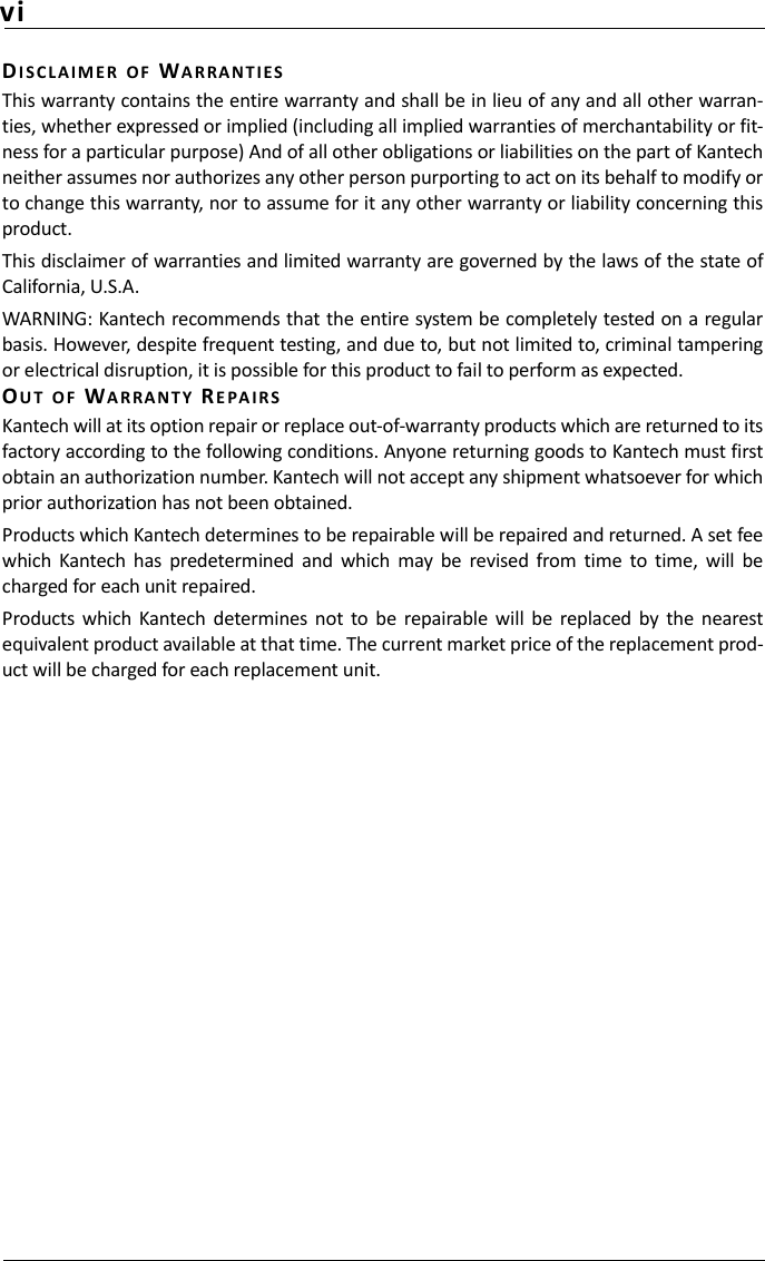
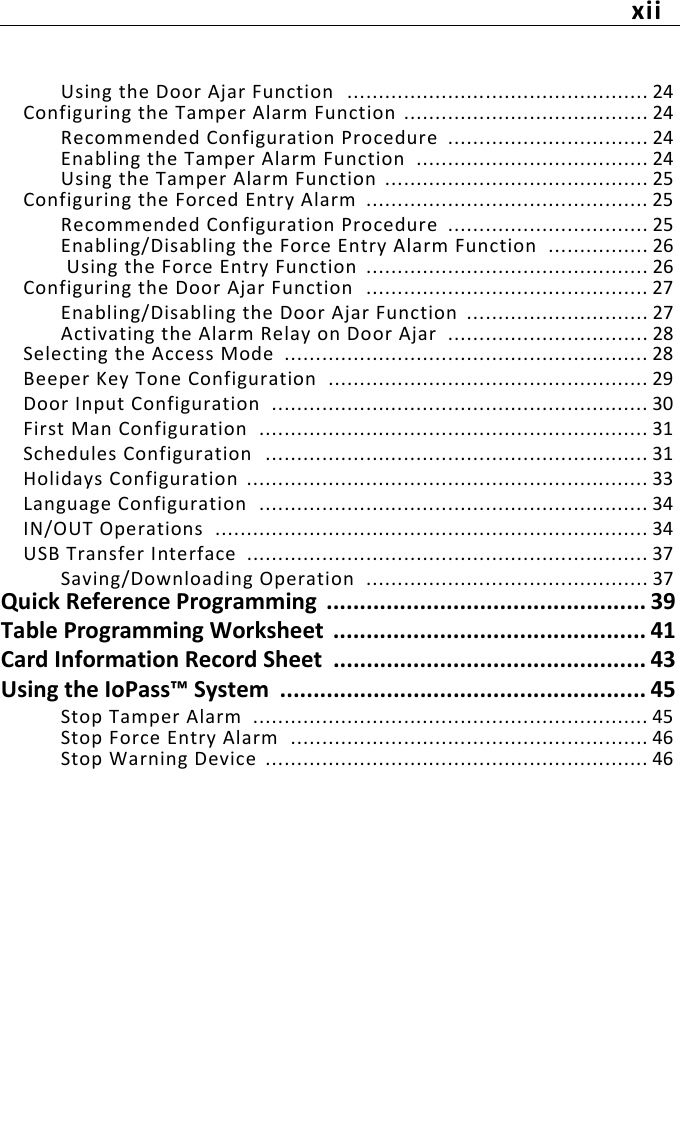
![404. SYSTEM1. ALARM1.TamperCURRENT:Press '1' --> Change2.ForceCURRENT:Press '1' --> Change3.AJAR1. Ajar alarmCURRENT:Press '1' --> Change2. Ajar relayCURRENT:Press '1' --> Change2. MODE1. AccessCURRENT: Press '1' --> Change2. ToneCURRENT: (ENABLED/DISABLED)Press '1' --> Change3. DI1. Exit buttonCURRENT:Press '1' --> Change2. Door contactCURRENT:Press '1' --> Change4. First man CURRENT: (ENABLED/DISABLED)Press '1' --> Change3.OTHER1. SCHEDULES1. Access scheduleSD I Start End00 1 00:00-00:00DAYS: SMTWTFS01 1 11111111. Unlock scheduleDN I Start End00 1 00:00-00:00DAYS: SMTWTFSUL 1 11111112. HOLIDAYS1. ReccuringHol [DATE]00 Month dd2. Non-recurringHol [DATE]00 Month dd3. LanguageENGLISHPress '1' --> Change4.IN / OUT1. CONFIG1. Load to UnitLoading xx%2. Save to USBSaving xx%2. CARD2. CARD1. Load to UnitLoading xx%2. Save to USBSaving xx%3. ReportSaving xx% Generate Events.csv file4. UpgradeFirmware upgradePress '1' to Execute](https://usermanual.wiki/TYCOFETY-KANTECH/12SA550/User-Guide-2011110-Page-52.png)
![41Table Programmin g WorksheetAccess Mode[4]-[2]-[1]Mode “0” - Card only (DEFAULT)Mode “1” - Card and PINMode “2” - Card OR PINTimersNOTE: Allowed from 1 to 255 seconds.Timers Default NewStrike [3]-[1] 10 seconds I__I__I__IAlarm [3]-[2] 10 seconds I__I__I__IAjar [3]-[3] 20 seconds I__I__I__I](https://usermanual.wiki/TYCOFETY-KANTECH/12SA550/User-Guide-2011110-Page-53.png)
![42System Functions NOTE: For more information, see "IoPass Factory Defaults" on page 11.Functions YES NOTamper alarm [4]-[1]-[1] Door forced open [4]-[1]-[2] Door ajar [4]-[1]-[3] Alarm relay activated on door ajar[4]-[1]-[3]-[2] Tone/beeper [4]-[2]-[2] Door contact type [4]-[2]-[3]-[2]NO NC Exit button contact type [4]-[2]-[3]-[1]NO NC ](https://usermanual.wiki/TYCOFETY-KANTECH/12SA550/User-Guide-2011110-Page-54.png)

![45Using the IoPass™ SystemBy default, the LED (indicator) is red, and the LCD of the ioPass unit displays:READY FOR CARDYou may have been given an access card, an access card and PIN or main password for the secured area. Depending on how the system is configured, the procedure remains the same: 1- Present your card at the reader OR enter the 6-digit password followed by the [#] key;2- The system will either grant you access (see step 4) or prompt you to enter your PIN:PASSWORD:3- Using the keypad, enter your 6-digit PIN followed by the [#] key. If you key in an incorrect password, the system will display “Invalid Password”. In this case, start from step 1.4- The LCD displays:ACCESS GRANTEDThe door will unlock and the LED (indicator) will turn green.NOTE: Do not give your PIN to anybody.Stop Tamper AlarmFollow this procedure to STOP the tamper alarm if it has beenactivated:1- When the tamper alarm has been activated, the alarm relay will be triggered (usually an annunciator) and the LCD will display:READY FOR CARDTAMPER ALARM (blink)2- This “Tamper Alarm” message is displayed and blinking and will remain on the LCD until an “access granted” operation is processed by the unit;3- Present your card and enter your PIN (depending on the system set up) followed by the [#] key. Access will be granted and the message will disappear.](https://usermanual.wiki/TYCOFETY-KANTECH/12SA550/User-Guide-2011110-Page-57.png)
![46Stop Force Entry AlarmFollow this procedure to STOP the force entry alarm if it has beenactivated.1- When the force entry has been activated, the alarm relay will be triggered (usually an annunciator) and the LCD will display:READY FOR CARDFORCE ENTRY2- This “Force Entry” message is displayed (and blinking) and will remain on the LCD until an “access granted” operation is processed by the unit;3- Present your card and enter your PIN (depending on the system set up) followed by the [#] key. Access will be granted and the message will disappear.Stop Warning DeviceDepending on whether the door ajar function is configured totrigger the alarm relay, follow this procedure to STOP the warningdevice.1- When the door is left open, the alarm relay might not trigger but the unit’s piezo will always sound. The LCD will display:READY FOR CARD DOOR OPEN2- The “Door Open” message is displayed (and blinking) and will remain on the LCD until the door is closed properly.](https://usermanual.wiki/TYCOFETY-KANTECH/12SA550/User-Guide-2011110-Page-58.png)