Tactical Electronics T100B VHF TRANSCEIVER User Manual T100
Tactical Electronics Corporation VHF TRANSCEIVER T100
UserManual.wiki
>
Tactical Electronics
>
T100B User Manual
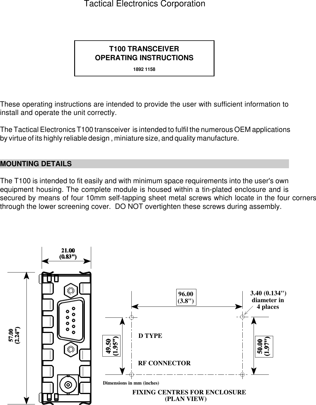
USERS MANUAL
Navigation menu
Upload a User Manual
Namespaces
Wiki Guide
HTML
PDF
Info
Views
User Manual
Discussion / Help
Navigation