Tactical Electronics T100B VHF TRANSCEIVER User Manual T100
Tactical Electronics Corporation VHF TRANSCEIVER T100
USERS MANUAL
T100 TRANSCEIVER
OPERATING INSTRUCTIONS
1892 1158
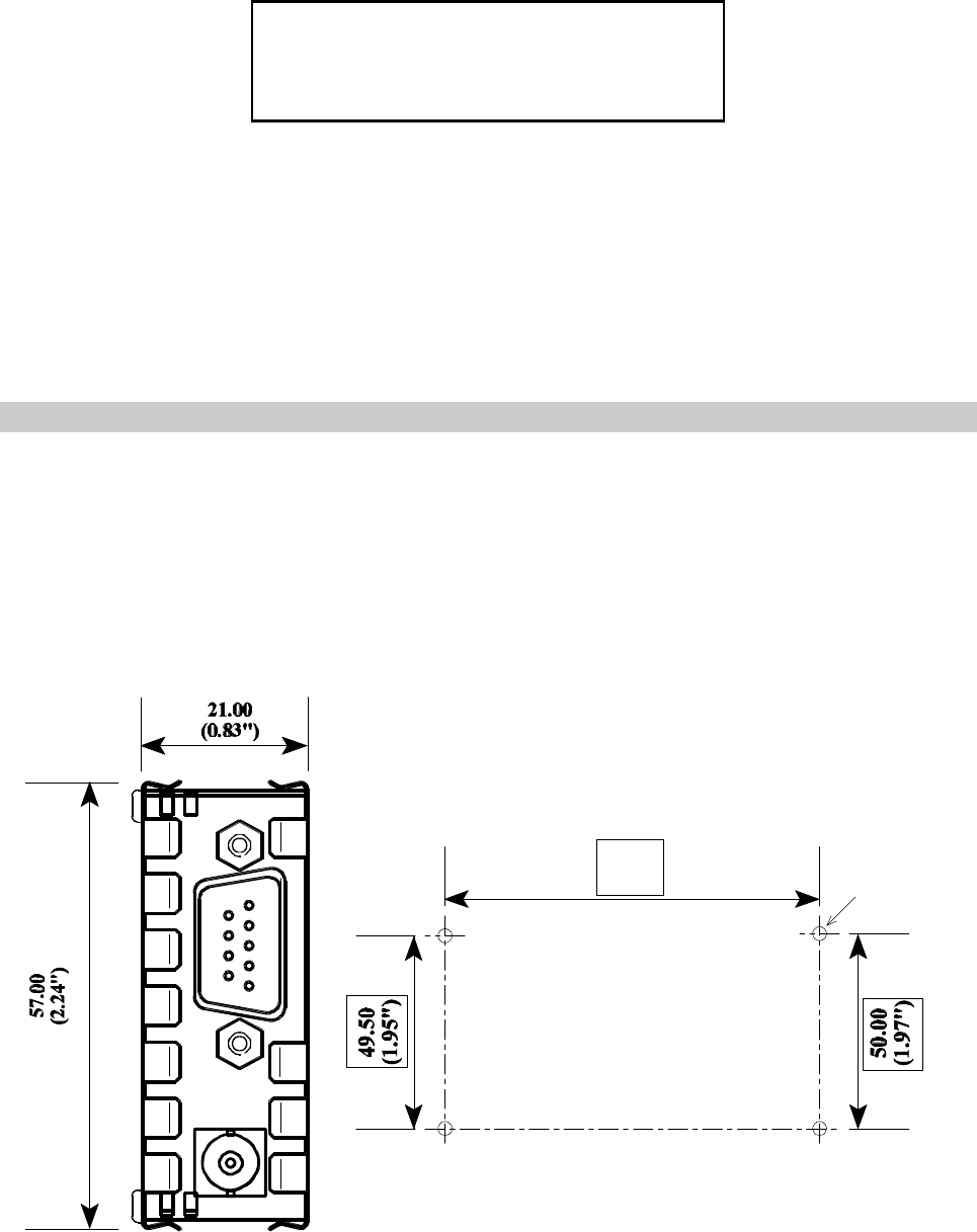
96.00
(3.8") 3.40 (0.134")
diameter in
4 places
FIXING CENTRES FOR ENCLOSURE
(PLAN VIEW)
Dimensions in mm (inches)
D TYPE
RF CONNECTOR
These operating instructions are intended to provide the user with sufficient information to
install and operate the unit correctly.
The Tactical Electronics T100 transceiver is intended to fulfil the numerous OEM applications
by virtue of its highly reliable design , miniature size, and quality manufacture.
MOUNTING DETAILS
The T100 is intended to fit easily and with minimum space requirements into the user's own
equipment housing. The complete module is housed within a tin-plated enclosure and is
secured by means of four 10mm self-tapping sheet metal screws which locate in the four corners
through the lower screening cover. DO NOT overtighten these screws during assembly.
Tactical Electronics Corporation

CONNECTION
The radio antenna connects by means of a BNC coaxial connector. All other
connections to the T100 transceiver are made using a standard 9-way D type connector as
detailed in the table below.
PIN NAME FUNCTION REMARKS
1MOD I/P Modulation input To transmitter;
Analog (750mV p-p for nominal
deviation) or
TTL/CMOS compatible (factory set)
2RX O/P Receiver Output Analog (350mV p-p) or
5V CMOS levels, high ( +5V) when no
signal present (factory set)
3bTbXbEtransmit enable HIGH >2.5V = receive
LOW <0.8V = transmitter enabled
40V 0 volts common DC and signal ground
5+ Vin positive supply +10 to +14 V DC
6SQF Squelch flag output HIGH (+5V, 10kS pull-up) = Signal
present
LOW (<0.8V) = Signal not present
7CS channel select Serial channel select input (RS232
compatible)
8RSSI Received Signal
Strength Indicator +1 to +3V DC nominal, 50dB range
90V 0 volts common DC and signal ground
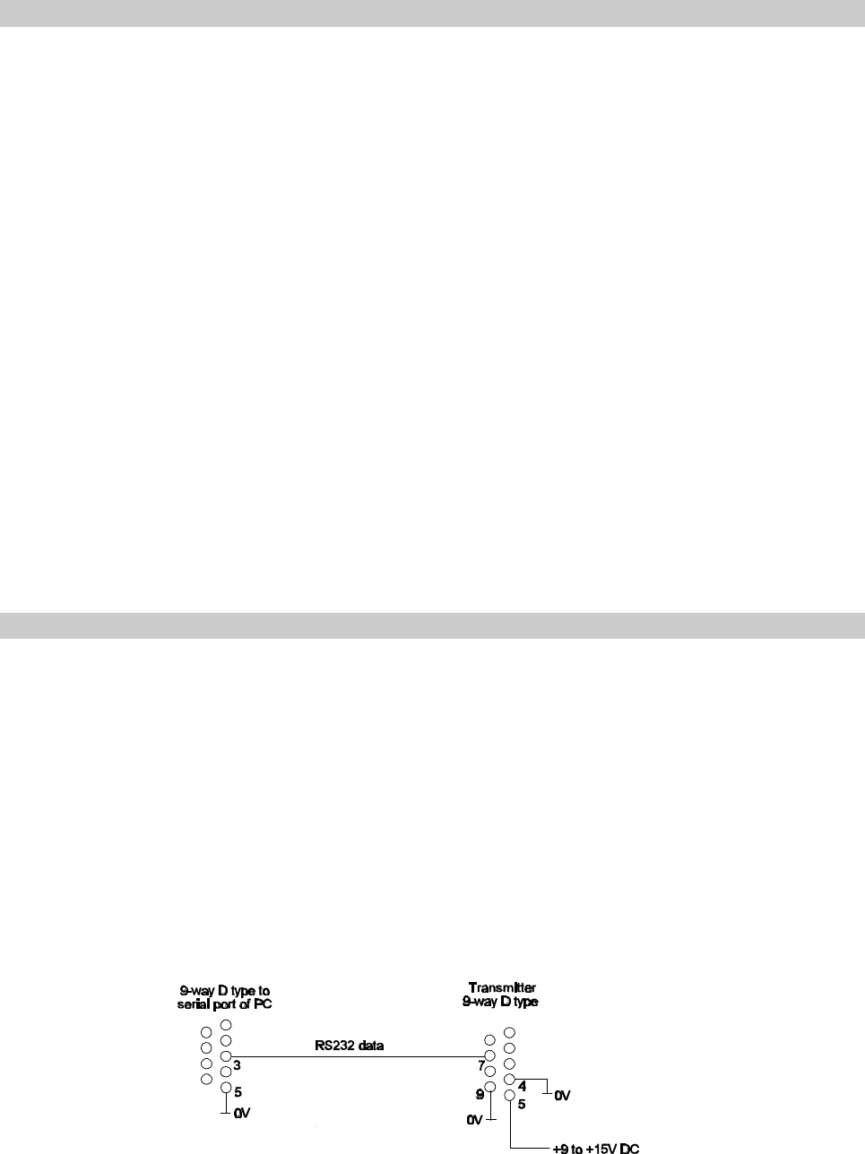
Figure 1 Programming adaptor
OPTIONS
Frequency and Channel spacing
The T100 is available in both 12.5 and 25kHz channel spacing variants within the following
frequency bands:
135 - 140 MHz
150 - 180 MHz
180 - 210 MHz
RF connection
As well as the standard BNC coaxial connector, the T100 is also available with a SMB or
flying lead RF connection. Contact Tactical Electronics Corporation for details.
Transmit Power
The maximum transmit power of the unit is 2W. This can be adjusted down to 100mW if
necessary for differing approved bands of operation.
CHANNEL SELECTION & PROGRAMMING
The software supplied with the T100 transmitter is the TLSPRG.exe program. The software
can be run on a PC with the serial port connected to pin 7 of the transmitter via a suitable
adaptor as shown in Figure 1. The unit may be programmed in-situ provided that pin 7 is
available. There is no feed-back facility with this circuit, and for this reason, the TLSPRG
software repeats the programming three times to eliminate error.
This version of software is programmed by a series of 8 byte data packets at 1200 baud.
Each packet includes a 16 bit sync code and an 11 bit checksum to eliminate the possibility
of spurious programming.

RUNNING THE SOFTWARE
Please note that mouse operation is not supported with this program
1. Connect the T100 transceiver to a suitable supply and to the PC using the
programming adaptor.
2. Insert the TLSPRG disk into drive A and type:
A:TLSPRG <return>
3. The user is then prompted to enter the serial port number of his PC which is used to
communicate with the TX00 transmitter. Enter 1 or 2.
4. Note: Do not select the port with the mouse connected as this will cause the
program to run incorrectly.
After the software has successfully loaded the screen displays the following prompts:
Enter frequency in MHz?
The user can then enter the required operating frequency and then ‘0' to quit.
RANGE INFORMATION
The following table gives an indication of the typical ranges to be expected between a
transmitter and receiver that have simple end-fed dipole antennas.
The following assumptions have been made in the calculations:
line-of-sight between antennas
0dB gain for the transmitter and receiver antennas
0dB loss for connectors and cables between the antenna and the radio connector
20dB fade and environmental margin
-100dBm received signal strength, allowing for digital and analog signals
Range versus TX power
Frequency (MHz) Power (mW) Power (dBm) Range (km) Range (miles)
173 100mW 20 13.8 8.5
173 500mW 27 30.9 19.1
173 1W 30 43.5 27.0
173 2W 33 61.5 38.2

TECHNICAL SPECIFICATION
Frequency of operation :135 to 210MHz (other frequency bands available)
Frequency bands :135 - 140 MHz
150 - 180 MHz
180 - 210 MHz
Switching bandwidth :3MHz within frequency bands
Channel spacing :12.5kHz (25kHz available as an option)
Number of RF channels :One, set by PIC micro controller changed by serial channel
select
RF output power :2W nominal at 12V DC
Frequency stability : ±2.5ppm over temperature range (12.5kHz version)
Supply voltage :+12V DC nominal (+10 to +14 volts max. range)
50% duty cycle maximum
Supply current Transmit :600mA typical at 2W
400mA typical at 1W
Receive :50mA typical
Size :119 x 57 x 21 mm (l x w x h) including connectors
4.69" x 2.24" x 0.83" (l x w x h) including connectors
Weight :120 gms (4.2 oz)
Temperature (operating) :-30 to +55 EC standard
Temperature (storage) :-30 to +70 CE