Tagsys L200TUNANT500 RFID PASSIVE TAG READER User Manual Conveyor Tunnel Reader V1 0
Tagsys S.A. RFID PASSIVE TAG READER Conveyor Tunnel Reader V1 0
UserManual.wiki
>
Tagsys
>
L200TUNANT500 User Manual
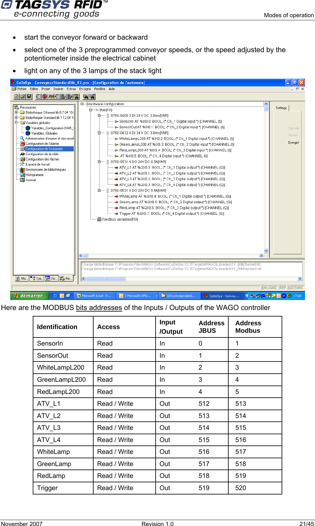
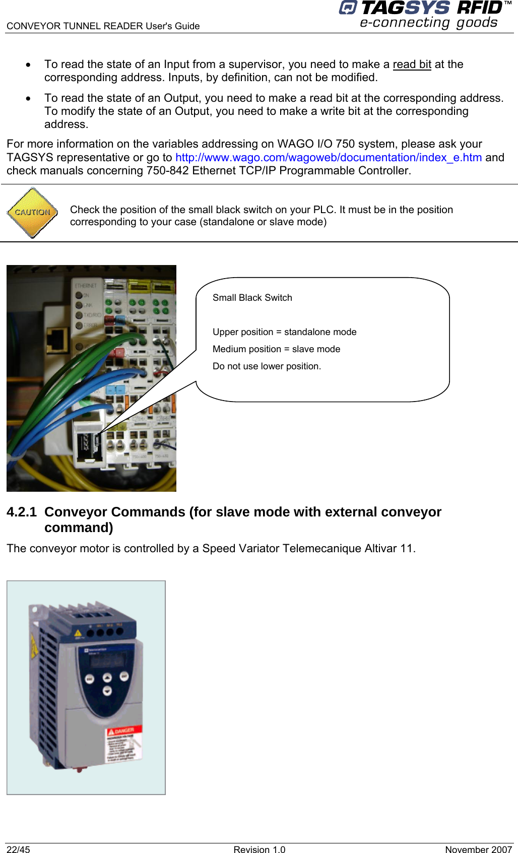
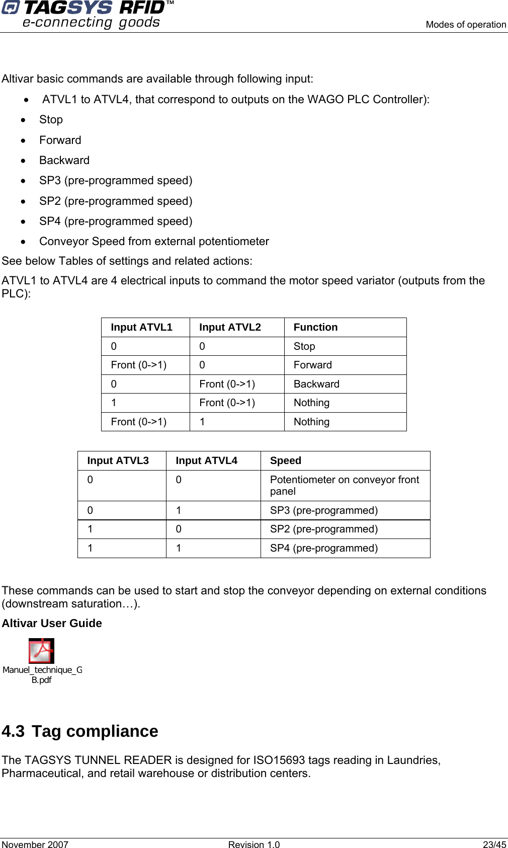
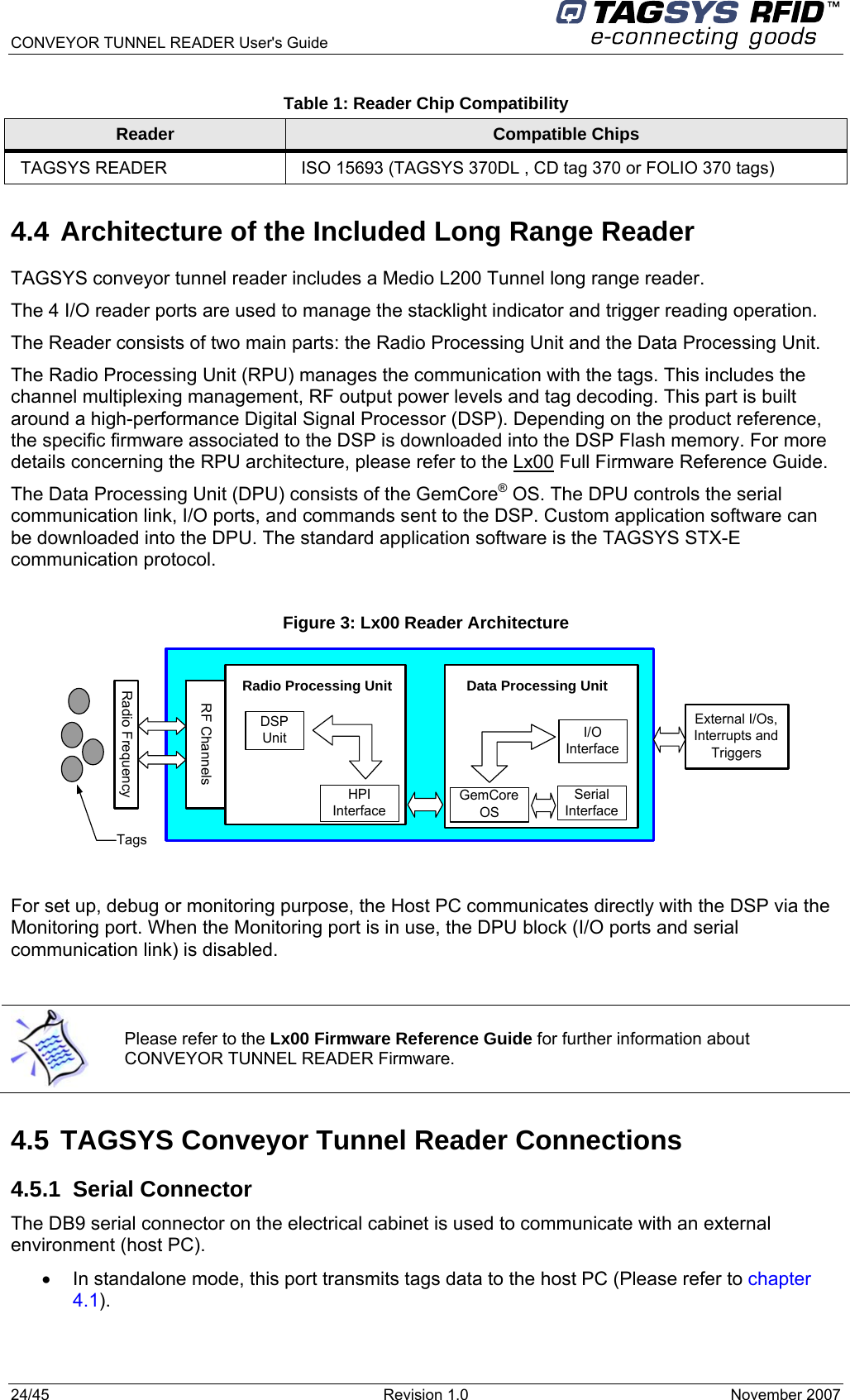
USERS MANUAL
Navigation menu
Upload a User Manual
Namespaces
Wiki Guide
HTML
PDF
Info
Views
User Manual
Discussion / Help
Navigation